Note: Descriptions are shown in the official language in which they were submitted.
CA 02605937 2007-07-31
CA 02596521 2007-07-31
Drive unit for medical devices
The invention relates to a drive unit, in particular a motive drive unit,
which is
suitable for portable medical devices and with the aid of which movements to
be
carried out slowly can be automated.
Prior art
In portable medical devices, such as, for example, glucose measuring devices,
the
automatic lanceting of a body point and the subsequent automatic recovery of
blood from the body orifice formed as a result of the lanceting operation play
an
essential part. To convert electrical energy from the long-term electrical
store, such
as, for example, accumulators or batteries, specific to the glucose measuring
devices into mechanical energy, electric motors or electromagnets are used, as
a
rule, according to the prior art. With the aid of these drive units, either a
pricking
movement is executed directly or a secondary mechanical energy store, for
example in the fonn of a spring is charged and is subsequently emptied highly
dynamically in order to generate the pricking movement (cf.
DE 10 2004 037 270.5). Particularly the charging of a spring element which may
be used as a secondary mechanical energy store requires a drive unit which is
capable of applying the spring force or the spring torque necessary for
prestressing
a torsion spring. In order to apply these high forces and torques, for
example,
direct-current motors used as electric motors are equipped with high-reduction
gears.
The electric motors used hitherto in glucose measuring systems must normally
be
equipped with a gear in order to increase the torque for prestressing a
secondary
mechanical energy store. However, these gears have poor efficiencies,
particularly
in the case of high step-up ratios. Moreover, the gears used cause running
noises
and take up a large construction space which, in glucose measuring devices, is
available to only a very limited extent for reasons of simple handling.
Moreover,
gears with high step-up are mostly provided with metal gearwheels and with
exact
mountings, thus making them very costly to produce. Consequently, gears with
high step-up, used for prestressing secondary mechanical energy stores, would,
on
the one hand, considerably enlarge the dimensions of an integrated glucose
measuring system and, on the other hand, considerably increase its production
costs, this being as highly undesirable as possible.
CA 02605937 2007-07-31
CA 02596521 2007-07-31
2
US 4,383,195 relates to a piezoelectrically actuated snap fastening. A
piezoelectric
actuator contains a piezoelectric element. A snap device is disclosed, by
means of
which a force can be generated which is directed in the opposite direction to
the
expansion generated by the piezoelectric element, a predetermined reaction
force
having to be overcome in order to trigger a snap-in of the snap device. The
piezoelectric element comprises piezoelectric means for providing a force
which
opposes the snap connection and which overshoots the reaction force, and also
means for applying an electrical field to the piezoelectric means, so that the
force
acting in the opposite direction can be generated and energy can be stored in
the
snap device, thus making the snapping of the device possible.
US 6,313,566 B1 relates to a piezoelectrically actuated motor. The
piezoelectric
motor disclosed contains a motor body and a layer connected to the motor body.
A
multiplicity of small legs are connected to this layer in such a way that the
small
legs are attached to a substrate. Each of the small legs contains a
piezoelectric
wafer. The actuation of a piezoelectrically active wafer displaces a
corresponding
small leg in relation to the substrate. This displacement generates a
transmission of
energy to the layer. The energy stored in this way in the layer can be
utilized in
such a way that the motor moves along the substrate. The small legs are
capable of
moving independently of one another and are likewise capable of moving
sequentially or within predetennined groups or units. The small legs may also
be
arranged in pairs, the individual small legs of a pair of small legs executing
a
simultaneous movement. The motor makes it possible to maintain a high holding
force when the energy supply is absent.
In light of the outlined disadvantages of the solutions known from the prior
art, the
object on which the invention is based is to provide a drive unit which is
distinguished, on the one hand, by small external dimensions and, on the other
hand, by an actuator which generates high actuating forces and which may be
arranged, for example, within a portable measuring device and fulfills a
plurality
of functions there.
Presentation of the invention
According to the invention, a drive unit, for example for a measuring device
or an
insulin pump, is proposed, which may comprise a pricking device for the
recovery
of body fluid and comprises an actuator which serves for charging a mechanical
energy store. The actuator may be designed, for example, as a piezoactuator,
its
length change when it is connected to a voltage source being transmitted by
means
CA 02605937 2007-07-31
CA 02596521 2007-07-31
3
of a transmission element to a nonreturn rotor for prestressing the mechanical
energy store. By virtue of the transmission element, the stroke of the
piezoactuator,
which amounts to only a few m, can be stepped up into a greater stroke which
is
transmitted to the nonretum rotor. The rotor is in this case assigned a
nonreturn
means which, when the length change of the piezoactuator is canceled, prevents
its
return movement into its initial position and preserves the stroke travel
covered
during the preceding cycle of the piezoactuator. In the case of an oscillating
voltage supply of the piezoactuator, the short-stroke piezoactuator movements
are
thus added to form a large overall stroke which acts on the nonreturn rotor.
The actuator of the drive unit proposed according to the invention may also be
implemented, in a further design variant which can be used to advantage, by a
diaphragm capable of being acted upon by a pressure medium. Advantageously, in
this design variant, a diaphragm material is used which executes a deflection
movement when a cavity is acted upon by pressure and which undergoes
deformation on account of the deflection. A deformation of the diaphragm
material
which occurs when the cavity closed by the diaphragm material is acted upon by
pressure can be transmitted to a step-up element which increases the stroke
movement according to a defined step-up ratio. In this design variant, the
stroke
achievable during the deformation of the diaphragm material when the latter is
deflected is dependent on the diaphragm material, on the material thickness of
the
diaphragm material and on the action of pressure upon the cavity closed by the
diaphragm material. The cavity, which is closed by the diaphragm material
according to this design variant, may be acted upon by a pressure medium, such
as,
for example, a gas, or be acted upon by liquids, such as H20 or oil.
As a further design variant of an actuator for a portable measuring device or
for an
insulin pump, the actuator may also be designed as a micromotor. The
micromotor
drives a cam of rounded form which has essentially an oval contour. During the
rotation of an output shaft of the micromotor, the cam connected fixedly in
terms
of rotation to the output shaft is set in rotation and contacts a step-up
element,
capable of being formed, for example, as a lever, once or several times per
revolution, depending on the design variant of the cam. An oscillating
movement
of a step-up element can thereby be achieved, the latter transmitting a
deflection of
a lever end caused by the rotational movement of the cam into a nonretum rotor
in
accordance with the step-up configuration of the step-up element.
In an advantageous development of the idea on which the invention is based, in
the
design variant with a piezoactuator the latter may be connected to an
oscillating
CA 02605937 2007-07-31
CA 02596521 2007-07-31
4
voltage source and be recharged. What can be achieved via the oscillating
voltage
supply of the piezoactuator is that the stroke movements, taking place with
high
forces during the length change of the piezoactuator comprising a stack of
piezocrystals, for the prestressing of, for example, a rotor designed as a
torsion or
leaf spring are transmitted without the need for a gear.
In particular, by a suitable choice of the step-up element between the
nonreturn
rotor and the piezoactuator, the step-up element can transmit length changes
of the
piezoactuator to the nonreturn rotor in a ratio of, for example, 1:25 and
above.
Consequently, a greater stroke can be transmitted to the nonretum rotor per
charging/discharging cycle of the piezoactuator, as compared to the stroke
movement which the piezocrystal stack of the piezoactuator executes according
to
its length change when a voltage is applied.
On account of the nonreturn means advantageously assigned to the nonreturn
rotor,
when the piezoactuator is discharged the stroke of the nonreturn rotor covered
during the previous length change can be preserved on the latter. The nonretum
means may be designed either as a ratchet wheel or as an external deformation,
such as, for example, a kind of external toothing, on the rotor guided in a
guide.
The nonretum means is preferably dimensioned such that its lost motion is kept
lower than the executed travel of the transmission element at its long end.
The
nonretum means assigned to the nonretum rotor has a lost motion which is lower
than the stroke achievable, for example, via a piezoactuator. This ensures
that the
actuator stroke at the prolonged end of the step-up element is also actually
transmitted to the nonreturn rotor and actually advances this during a
charging/discharging cycle of the piezoactuator. The lost motion of the
nonretum
means, comprising, for example, a detent pawl, which cooperates with a
toothing
on the nonretum rotor, corresponds to the amount of tooth spacing of the
toothing
on the nonreturn rotor.
In a design variant of the transmission element, the latter is designed as a
pivoting
lever which is rotatable about a pivot axis within a medical device for the
recovery
of body fluids. To implement a step-up ratio, the pivoting lever comprises a
first
and a second lever arm end which are produced in a different length, depending
on
the desired step-up ratio. The step-up element, which may be designed in the
form
of a pivoting lever, couples the stroke movement of the piezocrystal stack of
the
piezoactuator with the movement of the nonreturn rotor, whether it is a
ratchet
wheel or whether it is a rotor of block-shaped design which is guided in a
guide
and which has a positive or nonpositive nonreturn.
CA 02605937 2007-07-31
CA 02596521 2007-07-31
In a first design variant proposed according to the invention, an
oscillatingly
activated piezostack actuator with lever mimics and rotor is used. The lever
mechanism implements a step-up of the piezoactuator stroke, which is typically
between 3 m and 20 m, into a greater stroke of a few tenths of mm, such as,
for
5 example, between 0.3 and 0.5 mm. This greater stroke is transferred to the
nonreturn rotor. The prevention of the return movement of the rotor during the
contraction of the piezoactuator in the course of its discharging phase takes
place
by a nonreturn means which may be designed, for example, as a pawl detent.
Owing to the repetitions of charging/discharging cycles of the piezoactuator,
the
short-stroke actuator movements are added to form a large overall stroke.
According to this principle, mechanical energy can be stored in the mechanical
energy store acted upon by the nonreturn rotor, while this mechanical energy
store
may be designed, for example, as a linear or rotationally designed spring. In
a
similar way, by the rotor being prestressed continuously by means of the
piezoactuator, the movement of parts of a medical device, such as, for
example, of
a test strip or of a test strip drum, or the drive of an insulin pump can be
implemented.
The step-up element used, designed, for example, as a rotatably mounted lever
provided with different lever arms, can be produced as a plastic injection
molding
or as a metal stamping. The nonreturn rotor, whether it is a ratchet wheel or
whether it is a rotor of block-like design guided in guides, and also the
bearings
may likewise be manufactured as plastic injection moldings. Consequently, the
entire drive unit can be produced cost-effectively, requires a small amount of
construction volume and has extremely low noise. Moreover, what can be
achieved
by dispensing with a gear comprising a plurality of gearwheels is that very
high
efficiency is obtained, this being extremely important for the energy balance
in
medical devices for the recovery of body fluids or in insulin pumps.
In a further design variant proposed according to the invention, the
piezoactuator
capable of being used within a medical device, for example an insulin pump, is
activated by means of an alternating voltage of the desired operating
frequency.
The medical device may be, as well as an insulin pump, a measuring device or
analyzer with individual test strips or with a multiplicity of test strips
received in a
magazine. Furthermore, the proposed drive unit may be employed in integrated
systems with a pricking aid and with an evaluation unit for sample evaluation.
In
these devices, by means of the proposed drive unit, system functions, such as
the
triggering of the pricking operation, the transport and feed of the test strip
or the
transport of the test strip magazine can be achieved. Also, the proposed drive
unit
CA 02605937 2007-07-31
CA 02596521 2007-07-31
6
may be used in straightforward blood sampling devices. The longer the
piezocrystal stack of the piezoactuator used is, the greater the working
stroke is
which can be achieved. The stroke brought about by the length change of the
piezocrystal stack (typically 1.5 m length change per 1 mm of crystal stack
length) is transmitted to the coupled, rotatably mounted step-up element.
Owing to
the step-up ratio set by virtue of the design of the step-up element, the
stroke of the
lever tip, which acts, for example, on a nonretum rotor designed as a ratchet
wheel,
is increased. During the expansion of the piezoactuator, the ratchet wheel
rotates, a
nonretum means enabling this direction of rotation by means of a spring-loaded
rotational movement. During the contraction of the piezoactuator in the course
of
the discharge phase, the step-up element designed as a lever is reset into its
initial
position by spring force. In this case, the nonreturn means, which comprises a
detent pawl and the ratchet wheel, prevents the rotation of the ratchet wheel
opposite to the direction of rotation, with the result that a secondary energy
store
can be prestressed.
The nonretum means, which, according to this design variant, may comprise a
ratchet wheel and a detent pawl assigned to the latter, can alternatively also
be
designed as a clamping body freewheel, as a wrap spring freewheel or as a
frictional locking mechanism.
In a further design variant, a linearly operating arrangement of a drive unit
for a
medical device, for example an insulin pump, can be made available. According
to
this design variant, the piezostack actuator cooperates with a step-up element
of
lever-shaped design and a spring. According to this design variant, the
nonreturn
rotor is provided with a nonretum means which is of fishbone-like form. One
side
of the rotor of block-shaped design, guided in a guide, cooperates with the
guide
surrounding the rotor of block-shaped design, in such a way that the inclined
individual ribs on an outer face of the rotor are inclined with respect to the
prestressing movement of the rotor of block-shaped design. As a result, a
forward
movement of the rotor of block-shaped design becomes possible for the
prestressing of a secondary energy store, the reverse movement of which,
however,
is inhibited, during the discharge phase of the piezoactuator, on account of
the ribs
which come to bear against the linear guide.
In a further design variant of the drive unit proposed according to the
invention for
a medical device, for example for the recovery of body fluids, or an insulin
pump,
the piezoactuator can be assigned a rocker-shaped lever of a design bent in a
U-shaped manner. The lever serving as a step-up element and supported on a
CA 02605937 2007-07-31
CA 02596521 2007-07-31
7
bearing comprises a long and a short leg. The rocker-shaped lever is supported
on
an abutment of the housing. The piezoactuator stroke transmitted by the step-
up
element is converted radially into a rotational movement. According to this
design
variant, a shaft has two clamping roller freewheels, one of the outer rings of
one of
the clamping roller freewheels being connected firmly to the shaft. An outer
ring
of the other freewheel is connected stationarily to the device housing of the
medical device, for example for the recovery of body fluids, or of an insulin
pump.
A spring, formed on the device side, for a pricking aid for making a body
fluid
sampling orifice can be connected to the end of the shaft and be prestressed
as a
result of the rotational movement of the latter. After the triggering of, for
example,
a pricking aid, the spring expanded at the same time can be rotated anew
unidirectionally in one direction (360 drive).
In a further design variant of the solution proposed according to the
invention, the
drive unit is designed as an axially operating drive unit.
According to this design variant, the piezocrystal stack actuates a drive bell
via a
lever pincer having a solid joint. The drive bell is mounted rotatably on an
output
shaft. A rotational movement of the drive bell generated during the charging
phase
of the piezoactuator is transmitted to a freewheel star provided inside the
drive
bell. The freewheel star is, in turn, connected fixedly in terms of rotation
to the
output shaft. During the contraction of the piezoactuator in the course of the
discharge phase, a torsion spring rotates the drive bell back into its initial
position;
during this resetting movement, the freewheel star surrounded by the drive
bell and
consequently the output shaft cannot corotate back within a freewheel bell. On
account of the successive charging and discharging cycles of the
piezoactuator,
this gives rise on the output shaft to a unidirectional rotational movement
which
runs in one direction and which may be utilized for storing energy in a
mechanical
energy store. According to this axially operating design variant, the
nonreturn
means comprises the freewheel star, the drive bell and the freewheel bell.
Alternatively, in this design variant, a clamping body freewheel, a wrap
spring
freewheel or else a frictional locking mechanism may also be employed.
Drawings
The invention is described in more detail below with reference to the drawing
in
which:
CA 02605937 2007-07-31
CA 02596521 2007-07-31
8
figure 1 shows a first design variant of a drive provided with a nonreturn
means
and having a piezoactuator,
figure 2a shows a design variant of the nonretum means as a clamping body
freewheel,
figure 2b shows a design variant of the nonretum means as a wrap spring
freewheel,
figure 2c shows a design variant of the nonretum means as a frictional locking
mechanism,
figure 3 shows a design variant of a drive unit with a step-up ratio of, for
example, 1:25,
figure 4 shows a piezoactuator proposed according to the invention, integrated
into a pricking drive, for the tensioning of a pricking drive
spring, and
figure 5 shows a design variant of the drive unit proposed according to the
invention, in an axial embodiment with a small construction
volume,
figure 6 shows a design variant of the drive unit proposed according to the
invention, with a deflectable diaphragm,
figure 7 shows a further design variant of the drive unit proposed according
to
the invention, for portable measuring devices or insulin pumps,
with a micromotor,
figure 8 shows an illustration of a combination drive unit,
figure 9 shows a partial illustration of a system comprising a blood sampling
system and a magazine transport,
figures 10 and 11 show drum magazines with stored and pushed-out medical
commodities,
figure 12 shows a drum magazine received in an analyzer, and
CA 02605937 2007-07-31
CA 02596521 2007-07-31
9
figure 13 shows an insulin pump designed as a syringe.
Design variants
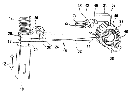
Figure 1 shows a first design variant of a drive unit, provided with a
nonretum
means, by means of a piezoactuator.
Medical devices are understood below to mean those devices which, to recover a
body fluid, such as, for example, blood, prick through the skin by means of
automatic lanceting and take blood from the extraction point thus made and
deliver
it to a test strip. The medical devices described in more detail below
comprise
either one or a multiplicity of test strips which are received in a magazine
or a
drum. When a medical device of this type is in operation, it is provided with
a
voltage source, whether it be a battery or an accumulator, via which actuators
serving as drives can be supplied with a voltage. The voltage sources
constitute
long-term electrical stores, the electrical energy of which is converted into
mechanical energy. The mechanical energy serves for triggering pricking
movements and/or for prestressing a secondary mechanical energy store, with
the
aid of which a pricking movement taking place highly dynamically can be
brought
about. Furthermore, the drive unit proposed according to the invention can be
employed as a drive unit for an insulin pump or for the transport of test
strips or of
a magazine, for example a drum magazine, receiving a multiplicity of test
strips.
Figure 1 shows a piezoactuator 10 comprising a multiplicity of piezocrystals
which
are arranged one above the other in the form of a stack. During the charging
phase
of the piezoactuator 10, a length change of each individual piezocrystal takes
place, which, added up, leads to a length change in the piezocrystal stack of
the
order of between 3 m and 20 m. In the illustration according to figure 1,
the
length change of the piezoactuator 10 is designated by the double arrow 12.
When
a voltage is applied during the charging phase of the piezoactuator 10, a
length
change takes place in the latter, the piezocrystal stack of the piezoactuator
10
contracting to its original length during the discharging phase of the
piezoactuator
10.
The piezoactuator 10 illustrated in figure 1 is assigned an actuator head 16
which
acts upon a first end 20 of a step-up element 18 of lever-shaped design. The
actuator head 16 acts, for example, upon a first lever arm 30 of the step-up
element
18, while a restoring element 14 designed as a spring is provided above the
first
lever arm 30 of the step-up element 18. The step-up element 18 of lever-shaped
CA 02605937 2007-07-31
CA 02596521 2007-07-31
design comprises the first end 20 already mentioned and a second end 22. The
step-up element 18 is mounted rotatably about an axis of rotation 24. When a
voltage is applied to the piezoactuator 10, the step-up element 18 executes a
movement in the direction of rotation 26. The axis of rotation 24 of the step-
up
5 element 18 is received, fixedly with respect to the housing, in a bearing
28.
Furthermore, the step-up element 18 of lever-shaped design comprises a second
lever arm 32, the second end 22 of which is assigned to a nonretum rotor
designed
as a ratchet wheel 36. As illustrated in figure 1, the ratchet wheel 36
comprises, for
example, a jagged toothing 50. The second end 22 of the step-up element 18
10 engages into the interspaces of the toothing 50.
A nonreturn means 34 is arranged above the nonreturn rotor designed as a
ratchet
wheel 36. The nonreturn means 34 is designed as a detent pawl 42 and is
movable
about a rotary bearing 46. The detent pawl 42 is itself acted upon by a
restoring
element 44. On the underside of the detent pawl 42 is located a hook 52 which
projects into the free spaces of the toothing 50 on the circumference of the
nonreturn rotor designed as a ratchet wheel 36.
During the charging phase of the piezoactuator 10, the latter executes a
length
change 12. As a result, the actuator head 16 moves the first lever arm 30 of
the
step-up element 18 upward counter to the action of the restoring element 14.
The
step-up element 18 is thereby pivoted in the direction of rotation 26 about
the axis
of rotation 24. The second end 22, fonmed on the second lever arm 32, of the
step-
up element 18 engages into the interspaces of the toothing 50 which is formed
on
the circumference of the nonretum rotor designed as a ratchet wheel 36, and
rotates the ratchet wheel 36 in the direction of rotation 38. A secondary
mechanical
energy store 40, illustrated as a torsion spring, is thereby prestressed.
During the
rotation of the nonretum rotor designed as a ratchet wheel 36 in the direction
of
rotation 38, the hook 52 formed on the underside of the detent pawl 42
travels, on
account of the geometry of the toothing 50 with a steep flank and a gradually
rising
flank, from free space to free space on the nonretum rotor, designed as a
ratchet
wheel 36, of the integrated measuring device. The secondary energy store 40 is
prestressed by virtue of the rotational movement of the ratchet whee136.
The nonretum means 34, comprising the detent paw142 which cooperates with an
external toothing 50 of a nonreturn rotor designed as a ratchet wheel 36, has
with
respect to the tooth spacing of the toothing 50 and to the hook-shaped
projection
52 a lost motion which is dimensioned smaller than, for example, a tooth
spacing
of the external toothing 50 of the ratchet wheel 36 via which the secondary
CA 02605937 2007-07-31
CA 02596521 2007-07-31
11
mechanical energy store 40 is prestressed. This ensures that, when voltage is
applied to a piezoactuator 10, its stroke travel also actually translates into
an
advancing movement, that is to say, in this case, into a rotational movement
of the
nonretum rotor designed as a ratchet wheel 36. If a toothing is provided on
the
ratchet wheel 36, the lost motion of the nonreturn means 34 is lower than the
tooth
spacing of the toothing on the circumference of the nonretum rotor 36 designed
as
a ratchet wheel.
When the charging phase of the piezoactuator 10 is ended, the length change 12
of
the piezocrystal stack which has occurred decreases during the discharging
phase
of the piezoactuator 10, and the piezoactuator 10 resumes its original length.
The
step-up element 18 is reset about the axis of rotation 24 by the restoring
element 14
assigned to the first lever arm 30. In order to prevent the nonreturn rotor
designed
as a ratchet wheel 36 from likewise executing a resetting movement during the
discharging phase of the piezoactuator 10, the hook 52 on the underside of the
spring-loaded detent pawl 42 blocks the return rotation of the rotor designed
as a
ratchet wheel 36 opposite to the direction of rotation 38. The nonreturn means
34,
that is to say the arrangement consisting of the nonretum rotor designed as a
ratchet whee136 and having an external toothing 50 and detent paw142, has a
lost
motion which is lower than the executed lever travel during the charging phase
of
the piezoactuator 10. On account of the design of the first lever arm 30 and
of the
second lever arni 32 in terms of the step-up ratio, for each
charging/discharging
cycle of the piezoactuator 10 the stroke of the latter can be increased, in
the event
of a length change 12 from 3 m to 20 gm, to a stroke travel at the second end
22
of the second lever arm 32 of a few tenths of mm, such as, for example, of
between
0.2 mm and 0.5 mm. Since the mechanical energy content of the secondary
mechanical energy store 40 recovered during the charging phase of the
piezoactuator 10 during the preceding charging phase of the piezoactuator 10
remains stored in the secondary energy store 40 because the return rotation of
the
nonretum rotor designed as a ratchet wheel 36 is prevented, during a
subsequent
charging/discharging cycle of the piezoactuator 10 a further rotation of the
nonreturn rotor designed as a ratchet wheel 36 in the direction of rotation 38
can be
achieved, so that, in the case of oscillating repetitions of the length change
12 on
the piezoactuator 10, a large overall stroke or a high overall rotation can be
achieved on the rotor, and a continuous prestressing of, for example, the
secondary
mechanical energy store 40 capable of being designed as a spring is achieved.
When the secondary mechanical energy store 40 is prestressed, it can be
emptied
highly dynamically, which may be utilized, for example, for canying out a
CA 02605937 2007-07-31
CA 02596521 2007-07-31
12
pricking movement of a lancet in a blood sampling device. This lancet, for
example, pricks the human skin, so that an outlet orifice for a body fluid,
such as,
for example, blood, is obtained. In addition to the highly dynamic emptying of
the
secondary mechanical energy store 40, which may be in the form of a torsion
spring, a helical spring or a linear spring, the movement of a test strip, of
a drum
receiving a plurality of test strips or of a differently configured test strip
magazine
in integrated medical devices, which are preferably designed to be portable,
can be
implemented via the energy content stored in the secondary mechanical energy
store 40. Furthermore, an insulin pump may be provided with a drive unit of
this
type.
The transmission element 18, which is preferably of lever-shaped design in the
design variant illustrated in figure 1, can be produced in a way which lowers
the
production costs, for example, as a plastic injection-molded component or as a
metal stamping. The nonreturn means 34 with a nonreturn rotor designed as a
ratchet wheel 36 and having an external toothing 50 can also be manufactured
as a
plastic injection-molded component. Thus, the drive unit for converting
electrical
energy of the long-term store into mechanical energy to be reserved in a
secondary
energy store 40 can be accommodated cost-effectively, in particular so as to
take
up little construction space, in the housing of a medical device. The proposed
drive
unit is distinguished, in particular, by a very low noise level, very high
efficiency
being achievable since a wheel mechanism is dispensed with. This, in turn, is
conducive to the service life of the long-term energy store, such as, for
example, an
accumulator or a battery, received in the medical device, for example an
insulin
pump.
Various design variants of nonreturn means which can be used within the
framework of the solution proposed according to the invention may be gathered
from the figure sequence of figures 2a, 2b and 2c.
Instead of the nonretum means 34 illustrated in the design variant according
to
figure 1, the nonreturn means 34 may also be designed as a clamping roller
freewheel 80. The clamping roller freewheel 80 illustrated in figure 2a
comprises a
plurality of clamping rollers 82. The clamping rollers 82 are acted upon via a
spring 84 and received in recesses 86 of a shaft 92. Each of the recesses 86
comprises a slope 88, the spring 84 which acts in each case upon the clamping
roller 82 being supported on a side of the recess 86 which is oriented
approximately perpendicularly with respect to the slope 88. The recess 86 is
surrounded by a tubular surface 90. During the clockwise movement of the
tubular
CA 02605937 2007-07-31
CA 02596521 2007-07-31
13
surface 90, the spring-loaded clamping rollers 82 are placed between the inner
face
of the tubular surface 90 and the slope 88, so that the shaft 92 in which the
recesses
86 are provided is also moved clockwise. If, by contrast, the surface 90 of
tubular
design is moved counterclockwise, the tubular surface 90 rotates in relation
to the
shaft 92, in which the recesses 86 are formed, freely, a take-up effect being
absent.
Accordingly, only during the rotation of the clamping body freewheel 80
counterclockwise, the clamping rollers 82 are clamped between the tubular
surface
90 and the shaft 92, in which the recesses 86 are formed, and thus give rise
to the
take-up effect.
A clamping roller freewheel with an inner star is designated by reference
symbol
100. Clamping bodies 106 of roller-shaped or spherical design are provided in
recesses 108 on the inner star 102. As soon as the clamping bodies 106 run
onto
the obliquely formed portions on the bottom of the respective recesses 108,
the
clamping bodies 106 come to bear against the inner face of the tubular body
104
and take up the latter counterclockwise according to the arrow depicted in the
middle of figure 2a. Via the clamping roller freewheel 100, illustrated in the
middle of figure 2a, with an inner star 102, either a freewheel or a clamping
connection can be achieved, depending on whether the tubular body 104 or the
shaft 110 is driven.
Furthermore, a further clamping body freewheel 80 may be gathered from the
illustration according to figure 2a, comprising an expanding band spring 114
in
which a plurality of drivers 116 are received, spaced apart from one another,
as
seen in the circumferential direction. Depending on the direction of rotation
of the
shaft 110, the drivers 116 fixed by the expanding band spring 114 come to bear
against the underside of the tubular surface 90 and thus bring about a
clamping
connection between the shaft 92, 110 and the tubular surface 90. The
individual
drivers 116, which are spaced apart from one another, as seen in the
circumferential direction, are held in double cages 112. A freewheel or a
clamping
connection between the shaft 92, 110 and a tubular body 90 can also be
implemented by means of the clamping body freewheel 80 formed on the right in
figure 2a, the clamping connection or the freewheel depending on whether the
tubular surface 90 or the shaft 92, 110 is driven. This affords degrees of
freedom as
regards the design of the clamping body freewheel 80 in terms of the output
side
and the drive side.
A wrap spring freewheel which would be used in the integrated measuring device
proposed according to the invention may be gathered from the illustration
according to figure 2b.
CA 02605937 2007-07-31
CA 02596521 2007-07-31
14
The wrap spring freewheel 120 illustrated in figure 2b comprises a spring 126
which is wrapped around a sleeve-shaped extension of a gearwheel. The drive
side
of the gearwheel is identified by reference symbol 122 and the output side by
reference symbol 124. The spring 126 arranged on the sleeve-shaped extension
of
the drive-side gearwheel 122 has a plurality of turns which surround the
sleeve-
shaped extension on the drive-side gearwheel 122. Depending on the direction
in
which the gearwheel 122 is driven on the drive side, the spring 126 is wrapped
to a
higher or lower degree around the sleeve-shaped tenon and thus drives the
shaft
received by the gearwheel arranged on the drive side 122 or allows this shaft
to run
freely.
Design variants of frictional locking mechanisms may be gathered from the
illustration according to figure 2c.
The design variant, illustrated in the illustration according to figure 1, of
the
nonretum means 34 may also be implemented by the frictional locking mechanism
illustrated in figure 2c. In the frictional locking mechanisms 130 illustrated
in
figure 2c, in each case either a clamping ring 132 of comb-shaped design or a
clamping body ring 144 provided with cams is illustrated. The comb-shaped
clamping ring 132 has a plurality of ribs arranged at an inclination which
bear
against the inner face of a roller 136 forming an output side 142. Depending
on the
direction in which the comb-shaped clamping ring 132 received fixedly in terms
of
rotation on a shaft 134 forming the drive side 140 rotates, the ribs of said
clamping
ring which project in a comb-shaped manner come to bear against the inner face
of
the roller 136. When the shaft 134 is operated clockwise, the roller 136 is
taken up.
If a rotation of the shaft 134 counterclockwise takes place, the ribs of comb-
shaped
design on the circumferential surface of the comb-shaped clamping ring 132
slip
past the inner circumferential surface of the roller 136.
Furthermore, a frictional locking mechanism 130 which contains a clamping body
ring 144 may be gathered from the illustration according to figure 2c. The
clamping body ring 144 comprises individual projections 138 which project in a
raised manner and which bear against the inner circumferential surface of a
roller
136. The roller 136 forms the output side of the frictional locking mechanism
130.
The frictional locking mechanism 130 is driven from the drive side 140 via the
shaft 134. When the shaft 134 is driven clockwise, the raised projections 138
are
moved away from the inner circumferential surface of the roller 136 on account
of
the offset between the raised projections 138 and the cams of the clamping
body
ring 144. When the shaft 134 is operated counterclockwise on the drive side
140,
CA 02605937 2007-07-31
CA 02596521 2007-07-31
the raised projections 138 provided on the outer circumferential surface of
the
clamping body ring 144 come to bear against the inner face of the roller 136
and
take up the latter counterclockwise.
5 A further design variant of the drive unit proposed according to the
invention for a
medical device, for example an insulin pump, may be gathered from the
illustration according to figure 3.
In a similar way to the illustration according to figure 1, a piezoactuator 10
is
10 provided which executes a length change 12 during a charging phase. When
voltage is applied to the piezoactuator 10, its actuator head 16 moves onto
the
underside of the step-up element 18 and deflects the step-up element 18 of
lever-
shaped design about its axis of rotation 24 in the direction of rotation 26.
In this
case, the restoring element 14 is compressed. The step-up element 18 of lever-
15 shaped design, illustrated in the design variant according to figure 3,
also
comprises a first lever arm 30 and a second lever arm 32, by means of the
length
dimension of which the step-up ratio of the step-up element 18 can be set.
While
the first end 20 of the step-up element 18 is moved upward about the axis of
rotation 24 during the pivoting movement of the step-up element 18, the second
end 22 of the second lever arm 32 moves downward with respect to the axis of
rotation 24. The tapering end of the second end 22 of the second lever ann 32
engages into a toothing on a first traveler side 158 of a nonretum traveler
154 of
block-shaped design. The nonreturn traveler 154 of block-shaped design is
movable linearly and is received in a guide 156. A nonretum means 152 is given
by the formation of a second traveler side 160 of the linearly movable
traveler 154
of block-shaped design. During a downward movement which is imparted to the
nonretum traveler 154 of block-shaped design during the deflection of the step-
up
element 18 about the axis of rotation 24, the traveler 154 of block-shaped
design
moves downward in a vertical direction according to the arrow and compresses
the
secondary energy store 40 which is designed as a helical spring in the
illustration
according to figure 3. By virtue of the configuration of the second traveler
side 160
with a rib structure of comb-shaped design with inclined ribs, the downward
movement of the traveler 154 of block-shaped design in the vertical direction
downward is not impeded. When the nonretum traveler 154 of block-shaped
design is deflected downward in the guide 156, the rib structure of comb-
shaped
design on the second traveler side 160 prevents the block-shaped nonretum
traveler 154 from moving back in its guide 156. This is brought about by the
respective ends of the ribs on the second traveler side 160 being brought to
bear
against the smooth inner face of the guide 156. The nonreturn traveler 154 of
CA 02605937 2007-07-31
CA 02596521 2007-07-31
16
block-shaped design therefore remains in its position during the discharging
phase
of the piezoactuator 10 until, at the next charging phase of the piezoactuator
10,
the second end 22 of the step-up element 18 of lever-shaped design is moved
downward anew and moves the traveler 154 of block-shaped design further
downward in its guide 156 as a result of engagement on the toothing on the
first
traveler side 158.
Consequently, the oscillating stroke movement of the piezoactuator 10 is
stepped
up into a continuously added-up stroke movement of the nonreturn traveler 154
of
block-shaped design. Depending on what lever lengths the first lever arm 30 or
the
second lever arm 32 has with respect to the axis of rotation 24 of the
transmission
element 18, a step-up of the length change 12 of the piezoactuator 10 into a
correspondingly greater stroke travel of the traveler 154 of block-shaped
design
can be achieved. The piezoactuator 10 is activated by means of an alternating
voltage of the desired operating frequency. The longer the piezoactuator 10
used is
designed to be, that is say the more piezocrystals are layered one above the
other,
the higher the length change 12 which can be achieved when voltage is applied
to
the piezoactuator 10. The length change of a piezocrystal stack normally
amounts
to 1.5 m per 1 mm of piezocrystal stack length.
The secondary energy store 40 acted upon by the nonreturn traveler 154 of
block-
shaped design may be designed as a torsion spring, as a helical spring or as a
linear
spring. The secondary energy store 40 may both be coupled to the nonreturn
traveler 154 of block-shaped design and constitute a separate component
decoupled from this. By means of the design variant, illustrated in figure 3,
of the
drive unit proposed according to the invention for converting electrical
energy into
mechanical energy within a medical device, a secondary mechanical energy store
40 for the highly dynamic triggering of a lanceting movement can be
prestressed,
test strip transport within the medical device can be carried out or an
advancing
movement of a test strip reservoir of drum-shaped or magazine-shaped design
within a medical device can be implemented. In addition, by means of the
proposed drive unit, an insulin pump in which extremely small stroke movements
are required over a long operating period can be driven.
A drive unit proposed according to the invention for tensioning a secondary
mechanical energy store for a pricking drive may be gathered from the
illustration
according to figure 4.
CA 02605937 2007-07-31
CA 02596521 2007-07-31
17
lt may be gathered from the illustration according to figure 4 that the
piezoactuator
is built into the medical device and is supported on the housing side against
an
abutment. The length change 12 of the piezocrystal stack of the piezoactuator
10 is
transmitted to the actuator head 16. The actuator head 16 rests in a cup-
shaped
5 recess of the first end 20 of a step-up element 18. According to the design
variant
illustrated in figure 4, the step-up element 18 is of angled design and
comprises the
first end 20 of the first lever arm 30 and the second end 22 on the second
lever arm
32. The step-up element 18 rests in a pivot bearing 174 against an abutment
176
provided fixedly with respect to the housing. During a length change 12 for
the
10 piezoactuator 10, a downward deflection of the first lever arm 30 takes
place, thus
leading to a lateral pivoting movement of the second lever anm 32 according to
the
double arrow 178 depicted. A pedestal 180 arranged at the second end 22 of the
second lever arm 32 acts on a cam 182 of a pricking drive 170. The stroke
stepped
up by the step-up element 18 during a length change 12 of the piezoactuator 10
is
transferred via the pedestal 180 at the second end 22 of the second lever arm
32 to
the cam 182. The cam 182 is connected fixedly to the outer ring of a first
clamping
roller freewheel 188. An outer ring of a second clamping roller freewheel 190
is
connected stationarily to the device housing 194 of the medical device. A
secondary mechanical energy store 40, provided on the device side, for the
pricking drive 170 is coupled to one end of the rotatable shaft 184 and is
prestressed during the deflection of the cam 182. The rotatably received shaft
184
is mounted in a shaft bearing 186 in the device housing 194 which is
reproduced
only partially in the illustration according to figure 4. While the first
clamping
roller freewheel 188 is connected on its outer ring to the cam 182 at a fixed
location, the outer ring of the second clamping roller freewheel 190 is
connected
stationarily to the device housing 194.
In the illustration according to figure 4, reference symbol 181 designates a
pressure
piece with a spherical head. The pressure piece 181 with a spherical head is
arranged opposite the pedestal 180 which is received at the second end 22 of
the
step-up element 18 of lever-shaped design. Inside the pressure piece 181 with
a
spherical head is located a spring 183 which acts with spring force upon the
spherical head of the pressure piece 181. Reference symbol 185 designates the
bisecting line of the shaft 184 received in the clamping roller freewheels 188
and
190. When the cam 182 is deflected during the charging phase of the
piezoactuator
10 via the step-up element 18 of lever-shaped design, the spherical head,
acted
upon by the spring element 183, of the pressure piece 181 is prestressed
counter to
the action of the spring element 183. The return of the cam 182 into its
initial
position takes place by means of the spring 183 which is present in the
pressure
piece 181 with a spherical head and which resets the cam 182 into its initial
CA 02605937 2007-07-31
CA 02596521 2007-07-31
18
position again during the discharging phase of the piezoactuator 10. The
stroke
movement of the step-up element 18 is thereby transmitted to the secondary
mechanical energy store 40 received at one end of the rotatable shaft 184.
A design variant of the drive unit proposed according to the invention, which
is
distinguished by an extremely low construction volume and an axial type of
construction may be gathered from the illustration according to figure 5.
It may be gathered from the illustration according to figure 5 that the
piezoactuator
10 is built into a medical device in an axial type of construction 200. A
lever
pincer 202 is provided, which has a solid joint 204, that is to say a point of
weakened cross section. The lever pincer 202 comprises a first pincer leg 206
and
a second pincer leg 208. In the event of a length change 12, the piezoactuator
10
acts in each case upon a first short leg 222 and upon a second short leg 224
of the
lever pincer 202. During the charging phase of the piezoactuator 10, that is
to say
during its length change 12, a drive bell 210 is actuated.
The drive bell 210 is mounted rotatably on an output shaft 218. The drive bell
210
comprises on one end face cams 226, 228 which are acted upon in each case by
extensions 230, 232 formed on the end faces of the pincer legs 206, 208. By
the
extensions 230, 232 being moved toward one another, the drive bell 210 is set
in
rotation according to the arrow given the reference symbol 38. The rotational
movement of the drive bell 210 thus generated is transmitted to a freewheel
220
designed as an inner star. The freewheel 220 designed as an inner star is
received
fixedly in terms of rotation on the output shaft 218. The drive bell 210 is
surrounded by a torsion spring 212. The ribs formed on the freewheel 220
designed as an inner star bear against an inner circumferential surface 216 of
the
drive bell 210. A freewheel bell 214 is provided coaxially to the drive bell
210 as a
separate component separate from the drive bell 210. The freewheel bell 214
comprises an antitwist device 234 of tenon-shaped design which lies in a
recess
236 between the first pincer leg 206 and the second pincer leg 208.
During the contraction of the piezoactuator 10, the drive bell 210 is reset
into its
initial position again by the torsion spring 212. A backward rotation of the
output
shaft 218 is ensured by the freewheel bell 214 and the freewheel 220 which
prevents a return rotation of the output shaft 218 opposite to the direction
of
rotation 38. During the discharging phase of the piezoactuator 10, the
rotational
movement of the output shaft 218 in the direction of rotation 38, caused by
the
rotation of the drive bell 210 during the previous application of voltage to
said
CA 02605937 2007-07-31
CA 02596521 2007-07-31
19
piezoactuator, is maintained, since a backward rotation of the output shaft
218
opposite to the direction of rotation 38 prevents a return rotation of the
output shaft
218 by means of the ribs of the freewheel system 220 which bear against the
inner
circumferential surface of the freewheel bell 214. By contrast, a rotation of
the
freewheel 220 in relation to the freewheel bell 214 can take place in the
direction
of rotation 38 when a rotational movement is imparted to the drive bell 210.
A further design variant of the drive unit according to the invention for a
medical
device or an insulin pump or the like may be gathered from figure 6.
Figure 6 illustrates an actuator 300 with a diaphragm. The actuator 300 is
formed
by a diaphragm which closes a cavity 302 capable of being acted upon by a
pressure medium. The diaphragm thickness of the diaphragm material is
identified
by reference symbol 304. The cavity 302 delimited by a wall 308 is acted upon
by
a gaseous medium, such as, for example, air, or by a liquid, such as, for
example,
water or oil. According to the action of pressure upon the cavity 302, a
deflection
306 of the diaphragm takes place - reproduced in figure 6 in the deflected
diaphragm position indicated by dashes. The cavity capable of being acted upon
by
a pressure medium 310 is closed sealingly by the diaphragm material. The
actuator
300 with a diaphragm acts in the direction 312 on the lever-shaped step-up
element
18 which can be used in this design variant. The step-up element 18 of lever-
shaped design can be actuated in the direction of rotation 26 about an axis of
rotation 420. The step-up element 18 comprises a first end 20 at the end of a
first
lever arm 30 and a second end 22 at the end of the second lever arm 32. The
first
lever arm 30 is acted upon by a restoring element 14 designed in spring form.
During the deflection 306 of the actuator 300 with a diaphragm, the diaphragm
material contacts the underside of the first lever arm 30 of the step-up
element 18
of lever-shaped design and deflects the step-up element 18 in the direction of
rotation 26 about the axis of rotation 24.
The second end 22 of the step-up element 18, said second end engaging into a
toothing 50 on the circumference of the nonretum rotor 36, here illustrated as
a
ratchet wheel, moves the nonreturn rotor 36 about its axis according to the
illustration in figure 6 and consequently prestresses the secondary mechanical
energy store 40 connected fixedly in terms of rotation to the nonreturn rotor.
A
return rotation of the nonretum rotor 36 is avoided by means of the nonretum
means 34. In the design variant according to figure 6, the nonretum means 34
is
designed as a detent paw142 which is arranged pivotably about the rotary
bearing
46. One end of the detent pawl 42 is acted upon by a prestressing element 44,
CA 02605937 2007-07-31
CA 02596521 2007-07-31
while the other end of the detent pawl 42 has formed on it a hook 52 which
engages into the interspaces of the toothing 50 on the outer circumference of
the
nonretum rotor 36 - designed here as a ratchet wheel.
5 In this design variant of the drive unit proposed according to the
invention, too, the
lost motion of the nonreturn means 34, that is to say of the detent pawl 42
and of
the external toothing 50, is dimensioned smaller than the stroke of the step-
up
element 18 of lever-shaped design at the second end 22 at which the latter
engages
into the toothing 50 of the nonretum rotor 36. This ensures that, during a
stroke of
10 the actuator 300 with a diaphragm, a rotational movement of the nonreturn
rotor 36
by the amount of at least one tooth spacing is actually achieved. In the
illustration
according to figure 6, the actuator 300 with a diaphragm is illustrated in a
design
variant of low build. The deflection 306, achievable by means of the actuator
300
with a diaphragm, for rotating the step-up element 18 of lever-shaped design
is
15 dependent on the selected diaphragm material and on the pressure to which
the
pressure medium 310 is exposed within the cavity 302. Depending on the degree
of deflection 306 of the diaphragm material, a lower or higher deflection of
the
first lever arm 30 about the axis of rotation 24 of the step-up element 18
and,
consequently, a smaller or larger stroke at the second end 22 of the second
lever
20 arm 32 of the step-up element 18 can be achieved.
A further design variant of the drive unit proposed according to the
invention, in
which a micromotor is used, may be gathered from the illustration according to
figure 7.
It may be gathered from the illustration according to figure 7 that an
actuator 400
with a micromotor is arranged at one end of the step-up element 18 of lever-
shaped
design. The actuator 400 with a micromotor comprises an output shaft 402 which
is driven in the direction of rotation 404. Located at the end of the output
shaft 402
is a cam 408 which has a contour 416 of oval design in the illustration
according to
figure 7. The cam 408 illustrated in the illustration according to figure 7
touches a
contact surface 406 on the underside of the first lever arm 30 of the step-up
element 18 of lever-shaped design once per revolution. For this purpose, the
cam
408 has a contact point 414. In that position of the cam 408 which is
illustrated by
unbroken lines, the contact point 414 touches the contact surface 406 the
first lever
arm 30 and deflects the step-up element 18 of lever-shaped design about the
axis
of rotation 24 in the direction of rotation 26 counter to the action of the
restoring
element 14.
CA 02605937 2007-07-31
CA 02596521 2007-07-31
21
Instead of the cam 408 illustrated in figure 7 and provided on the output
shaft 402
of the actuator 400 with a micromotor, a cam could also be used which touches
the
contact surface 406 of the first lever ann 30 at least twice or even more
often per
revolution.
According to the rotation of the actuator 400 with a micromotor, an
oscillating
deflection of the first lever arm 30 of the step-up element 18 of lever-shaped
design and, consequently, a deflection of the second end 22 of the second
lever
arm 32 of the step-up element 18 of lever-shaped design takes place. As a
result,
the nonreturn rotor, designed as a ratchet wheel in the design variant
according to
figure 7, has imparted to it a rotational movement which it transmits to the
secondary mechanical energy store 40. During the return of the step-up element
18
of lever-shaped design, that is to say in the event that the contact point 414
of the
cam 408 just avoids touching the contact surface 406 during a revolution of
the
cam 408, a return rotation of the nonreturn rotor 36 is prevented by the
nonretum
means 34.
In the design variant illustrated in figure 7, the nonreturn means 34 is
similar to the
nonreturn means of the design variant according to figure 6. The lost motion
of the
nonreturn means 34 is in this case dimensioned such that it is lower than the
stroke
of the second end 22 on the second lever arm 32 of the step-up element 18 of
lever-shaped design. This ensures that, during a deflection of the first lever
arm 30
about the axis of rotation 24 of the step-up element 18, a rotation of the
nonretum
rotor 36 provided with a toothing 50 and designed as a ratchet wheel can be
achieved.
Thus, the stroke movement at the second end 22 of the step-up element 18,
previously achieved during a deflection of the step-up element 18 at the first
end
20 of the first lever arm 30, leads to a rotational movement of the nonretum
rotor
36 counterclockwise, the return rotational movement of the nonreturn rotor 36
being prevented by the nonreturn means 34. In this way, an energy content can
be
stored in the \secondary mechanical energy store 40 according to the working
strokes of the step-up element 18 and can be utilized for triggering functions
in a
medical device, such as, for example, an insulin pump.
Figure 8 shows an illustration of a combination drive unit for a medical
device.
The combination drive unit 500 illustrated in figure 8 comprises a secondary
mechanical energy store 502 which is reproduced only diagrammatically in the
CA 02605937 2007-07-31
CA 02596521 2007-07-31
22
illustration according to figure 8. A gearwheel 504 is mounted rotatably in
the
combination drive unit 500 and can be rotated in both directions of rotation
according to the double arrow 512. The gearwheel 504 is coupled both to the
secondary mechanical energy store 502 for storing mechanical energy and
directly
to a housing side of a drum magazine 504. When the gearwheel 504 is driven by
a
design variant of the above-described piezoactuator 10, a rotation of the
gearwheel
504 takes place, with the result that the secondary mechanical energy store
502 is
compressed. On the other hand, the gearwheel 504 engages into a
correspondingly
configured bottom of the drum magazine 506, so that the drum magazine 506 is
rotated about its axis of rotation 514. The magazine may be provided, for
example,
for the storage of test strips or lancets, so that a rotation of the drum
magazine 506
takes place in such a way that a disposable in the drum magazine 506 is
positioned
correspondingly to an extraction unit in the medical device. Thus, it is
conceivable,
for example, that, during the tensioning of the secondary mechanical energy
store
502 for driving a lancet, an advance of the drum magazine 506 about its axis
of
rotation 514 occurs simultaneously, so that a test strip can be extracted from
the
drum magazine 506 for sampling by means of an extraction unit provided for
this
purpose, for example by means of a plunger. The direction of rotation of the
drum
magazine 506 about the axis of rotation 514 is illustrated by the arrow 514.
Figure 9 shows a partial illustration of an integrated system comprising a
blood
sampling system and a magazine transport.
It may be gathered from the illustration according to figure 9 that an
integrated
system 530 comprises a pricking aid 532 and a drum magazine 506, not
illustrated,
but which may be gathered diagrammatically from figure 8. The drum magazine
not illustrated in figure 9 is driven by means of a shaft 534. The shaft 534
comprises, at its end facing the drum magazine, a toothed structure 536 which
functions as a driver for the drum magazine not illustrated in figure 9. The
pricking
aid 532 is accommodated in the lower region of the integrated system 530
according to the illustration in figure 9. An advance of the shaft 534 and the
associated rotational movement of the drum magazine 506 according to figure 8
can be achieved by means of a drive unit proposed according to the invention,
as
described above. For this purpose, the shaft 534 may be coupled, for example,
to
the output shaft 218 according to the illustration in figure 5. The
piezoactuator 200,
illustrated there, in an axial form of construction can, in addition to the
shaft 534,
also actuate the spiral spring 538 prestressing the pricking aid 532. The
secondary
mechanical energy store can be designed both as a helical spring 40 and as a
spiral
spring 538 indicated diagrammatically in figure 9. Furthermore, the nonretum
CA 02605937 2007-07-31
= CA 02596521 2007-07-31
23
rotor, which can be designed as a ratchet wheel 36, may be gathered from
figure 9,
on which the piezoactuator 200 according to figure 5 acts. Of course, it is
possible,
in the integrated system 530 apparent from figure 9, also to employ the design
variants of the drive unit proposed according to the invention according to
figuresl,4and6and7.
Drum magazines with stored and pushed-out medical commodities may be
gathered from the illustrations of figures 10 and 11.
A drum magazine 506 which is rotatable about its axis of rotation 514 can be
gathered from the illustration according to figure 10. The drum magazine 506
according to the illustration in figure 10 contains a plurality of medical
commodities illustrated in their storage position 552. These may take the form
of,
for example, test strips having a sample application surface 564. The
commodities
550 are moved by means of a plunger 560 from their storage position 552
illustrated in figure 10 into the extraction position 554 illustrated in
figure 11.
According to the illustration in figures 10 and 11, it may be gathered that
the drum
magazine 506 is assigned in each case a conveying roller 556 and a
counterroller
558, between which a transport gap designated by reference symbol 562
prevails.
As soon as the plunger 560 is activated, the respective medical commodity 550
is
pushed out of its storage position 552 in the drum magazine 506 into the gap
562.
It may be gathered from figure 11 that the medical commodity 550 illustrated
here
in test strip form is pushed into the transport gap 562 between the conveying
roller
556 and the counterroller 558. The driven conveying roller 556 grasps the
medical
commodity 550, illustrated here in strip form, and conveys it into its
extraction
position 554, as illustrated in figure 11. The drum magazines 506 illustrated
in
figures 10 and 11 may be integrated into an integrated system according to the
illustration in fig. 9.
Figure 12 shows a drum magazine received in an analyzer.
It may be gathered from the illustration according to figure 12 that the
analyzer
580 comprises a positioning device 582, by means of which the individual
medical
commodities 592 - here in the form of test strips - received in the drum
magazine
506 are positioned before being used by the user. The drum magazine 506 is
driven
by a drive unit 584. The drive unit 584 may itself be driven via an output
shaft 218
of one of the drive units according to the above-described design variants in
figure 1, figure 3, figure 4 and according to figures 5 to 7. When the drive
unit
proposed according to the invention is received in the analyzer 580, an
installation
CA 02605937 2007-07-31
CA 02596521 2007-07-31
24
space 586 is provided in the latter, which provides room for accommodating the
drive unit proposed according to the invention. The analyzer 580 has a frame
594
for stiffening. For the sake of completeness, it may be mentioned that the
drum
magazine 506 has a multiplicity of reception chambers 588 which on one of
their
end faces contain in each case an extraction orifice 590 via which the test
strips
592 can be delivered to the positioning device 582. The drum magazine 506
which
is driven by the drive unit proposed according to the invention is moved about
its
axis of rotation 514.
An insulin pump designed as a syringe may be gathered from the illustration
according to figure 13.
The insulin pump 610 illustrated in figure 13 comprises a housing 630. A drive
sleeve 618 which has an external toothing 26 is introduced into the housing
630.
The external toothing 620 has meshing with it a driving wheel 612 which may be
received, for example, on the output shaft 218 of the piezoactuator 200,
illustrated
in figure 5, of an axial form of construction. By the drive unit being
combined, as
proposed according to the invention, with a medical device, such as an insulin
pump 610, a particularly long feed of a piston 626 is achieved which conveys
the
active substance - insulin in the present case - received in an ampoule 624 in
the
smallest possible quantities, but continuously, into a hose 632 which is
connected
to a catheter received in the human body. The insulin pump 610 according to
the
illustration in figure 13 comprises a threaded rod, the thread of which meshes
with
the intemal toothing of a disk 628 having an external thread. On account of
the
extemal thread, the disk 628 is mounted fixedly in terms of rotation in the
housing
630. When the threaded rod 616 is rotated continuously by means of the disk
628,
the piston 626 moves continuously with the smallest possible feed into the
ampoule 624. The ampoule 624 is locked in the housing 630 by means of a
connection piece 636 and a cap 634 integrated into the latte.
CA 02605937 2007-07-31
CA 02596521 2007-07-31
List of reference symbols
10 Piezoactuator
12 Length change
14 Restoring element
16 Actuator head
18 Step-up element (lever-shaped)
20 First end
22 Second end
24 Axis of rotation
26 Direction of rotation step-up element
28 Bearing step-up element
First lever arm
32 Second lever arm
34 Nonreturn means
36 Ratchet wheel
38 Direction of rotation ratchet wheel
Secondary mechanical energy store
42 Detent pawl
44 Restoring element for detent pawl
46 Rotary bearing detent pawl
48 Direction of rotation detent pawl
Toothing
52 Hook
80 Clamping body freewheel
82 Clamping roller
84 Spring
86 Recess
88 Slope
90 Tubular surface
92 Shaft
100 Clamping roller freewheel with inner star
102 Inner star
104 Tubular body
106 Clamping body
108 Recess
CA 02605937 2007-07-31
CA 02596521 2007-07-31
26
110 Shaft
112 Double cage
114 Expanding band spring
116 Driver
120 Wrap spring coupling
122 Drive side
124 Output side
126 Spring
130 Frictional locking mechanism
132 Comb-shaped clamping ring
134 Shaft
136 Roller
138 Raised projections
140 Drive side
142 Output side
144 Clamping body ring
150 Piezoactuator with linear operation
152 Nonreturn means
154 Traveler
156 Guide
158 First traveler side
160 Second traveler side
170 Pricking drive (360 drive)
172 Pressure piece
174 Pivot bearing for lever
176 Abutment
178 Pivoting range first lever arm
180 Pedestal
181 Pressure piece with spherical head
182 Cam
183 Spring
184 Rotatable shaft
185 Axis of synimetry
186 Shaft bearing
188 First clamping roller freewheel
CA 02605937 2007-07-31
CA 02596521 2007-07-31
27
190 Second clamping roller freewhee1192
192 Outer ring first clamping roller freewheel
194 Device housing
200 Piezoactuator of axial form of construction
202 Lever pincer
204 Solid joint
206 First pincer leg
208 Second pincer leg
210 Drive bell
212 Torsion spring
214 Freewheel bell
216 Inner circumferential surface
218 Output shaft
220 Freewheel system
222 First short leg
224 Second short leg
226 First cam
228 Second cam
230 First extension (206)
232 Second extension (208)
234 Antitwist device
236 Recess
300 Actuator with diaphragm
302 Cavity
304 Diaphragm thickness
306 Deflection
308 Wall of the cavity 302
310 Pressure medium
312 Direction of action on diaphragm
400 Actuator with micromotor
402 Output shaft
404 Direction of rotation
406 Contact surface
408 Cam
410 Electrical connection
412 90 rotation
CA 02605937 2007-07-31
CA 02596521 2007-07-31
28
414 Contact points cam 408
416 Oval contour
500 Combination drive unit
502 Secondary mechanical energy store
504 Gearwheel
506 Drum magazine
508 Shaft
510 Direction of rotation
512 Direction of rotation gearwheel
514 Axis of rotation drum magazine
530 Integrated system with pricking aid and magazine transport
532 Pricking aid
534 Shaft
536 Toothed structure (driver drum magazine)
538 Spiral spring
550 Medical commodity
552 Storage position commodity
554 Extraction position commodity
556 Conveying roller
558 Counterroller
560 Plunger
562 Gap
564 Sainple application surface
580 Analyzer
582 Positioning device
584 Drum drive
586 Installation space for piezoactuator
588 Reception chambers
590 Extraction orifice
592 Test strip
594 Frame
610 Insulin pump
612 Driving wheel
614 Output shaft (as 218)
CA 02605937 2007-07-31
CA 02596521 2007-07-31
29
616 Threaded rod
618 Drive sleeve
620 External toothing
622 Disk
624 Ampoule
626 Piston
628 Disk with external thread
630 Housing
632 Hose
634 Cap
636 Outlet piece