Note: Descriptions are shown in the official language in which they were submitted.
CA 02606000 2007-10-23
WO 2006/118793 PCT/US2006/014690
IDENTIFICATION OF ELECTRODES FOR NERVE STIMULATION IN THE
TREATMENT OF EATING DISORDERS
CROSS-REFERENCE TO RELATED APPLICATIONS
[0001] The present invention is a related application to United States Patent
Application Serial No.
11/118,452, entitled "Weight Loss Device and Method," and United States Patent
Application
Serial No. 11/118,980, entitled "Noninvasively Adjustable Gastric Band." Both
applications are
filed on the same date as the present application and in the name of same
inventors.
BACKGROUND OF THE INVENTION
Field of the Invention
[00021 The present invention generally relates to apparatus and methods for
treatment of eating
disorders, such as obesity, bulinnia nervosa, and anorexia nervosa, and more
particularly to
treatments and therapies which employ vagus nerve stimulation in the
esophageal/gastric area of
the body in conjunction with gastric restriction.
Description of Related Art
[0003] Increasing prevalence of obesity is one of the most serious and
widespread health problems
in the world. It is estimated that about 6% of the current population of the
United States is
morbidly obese, defined as having a body mass index of more than forty, or as
is more commonly
understood, being more than one hundred pounds overweight for a person of
average height. In
addition to the morbidly obese, a much larger percentage of the population is
either obese or
significantly overweight. Aside from what may be an epidemic of obesity, it is
believed by some
health experts that obesity is one of the first two leading causes of
preventable deaths in the United
States, either ahead of or just behind cigarette smoking.
[0004] The classical treatment regimen for obese persons, which combines
nutritional counseling
with exercise and education, has demonstrated relatively little long term
success. In general,
liquid diets and pharmaceutical agents can bring about acute, but rarely
lasting, weight
loss. Surgery to provide either gastric restriction or malabsorption in cases
of severe obesity have
shown the greatest success long-term, but are major surgical procedures that
can lead to emotional
problems, and which have their share of failures (see, e.g., Kriwanek,
"Therapeutic failures after
gastric bypass operations for morbid obesity," Langenbecks Archiv. Fur
Chirurgie, 38(2): 70-74,
1995).
[00051 Among the surgical approaches to the treatment of morbid obesity,
various stomach
banding or gastroplasty ring devices have been employed for gastric
restriction (i.e., decreasing the
size of the stomach) to reduce food intake. For example, U.S. Pat. No.
4,592,339 (Mentor
Corporation), U.S. Pat. Nos. 5,074,868, 5,226,429 and 5,601,604 (Inamed
Development Co.), and
1
CA 02606000 2007-10-23
WO 2006/118793 PCT/US2006/014690
U.S. Pat. Nos. 5,771,903 and 6,102,922 (Kirk Promotions Limited). Some of the
known gastric
bands have incorporated an inflatable member for adjusting the diameter of the
stoma opening
created by the band.
[0006] There have also been efforts to treat obesity, and syndromes related to
motor disorders of
the stomach of a patient, by altering natural gastric motility of the patient.
For example, U.S. Pat.
No. 5,423,872 (Cigaina) identifies a "gastric pacemaker" region of the
stomach, at a point
proximate to the greater curvature, at which propulsive gastric movements
begin and from which
electrical pulses (depolarization potential) spread in an anterograde
direction along the entire
stomach. The patent describes a process of altering, by means of sequential
electrical pulses and
for preset periods of time, the natural gastric motility of a patient and/or
the time and manner of
contraction of the lower esophageal and pyloric sphincters to prevent emptying
(or to slow down)
gastric transit, to prevent duodenal acidification during interdigestive
phases, or to prevent gastric
reflux in the last portion of the esophagus. The stimulator device is placed
subcutaneously in the
abdominal wall and is connected to the distal gastric antrum by means of an
electrocatheter.
[0007] U.S. Pat. No. 5,690,691 (The Center for Innovative Technology)
describes an implantable
or portable gastrointestional pacemaker for any organ in the gastro-intestinal
tract through which
peristaltic movement of material is controlled by natural electrical pacing,
and includes multiple
electrodes that are positionable at multiple sites on a single organ or on
different sites on different
organs. Feedback from the gastro-intestinal tract can be provided by one or
more sensor
electrodes.
[0008] U.S. Pat. App. Pub. No. 2003/0208212 (Cigaina) describes a removable
gastric band which
may be paired with the use of a gastric electrostimulator for inducing forced
slimming in the initial
phase of treatment for morbigenous obesity. Such electrostimulation devices
may either be
incorporated into the removable gastric band or located at a distance from the
removable gastric
band.
[0009] U.S. Pat. No. 6,510,332 (Transneuronix, Inc.) describes an implant
device for
electrostimulation and/or electrical monitoring of endo-abdominal tissue or
viscera. In the
background discussion of that patent it is said that stimulation of the
intrinsic nervous system of the
stomach is likely to have two major consequences or effects: (1) the
correction and direct control
of the electromotor activity of the intestines and (2) the stimulation of
increased incretion of
specific substances (i.e., gastroenteric neuromediators) produced by the
intrinsic nervous system
itself thorough the myenteric plexus.
[0010] In addition to electrical stimulation of gastrointestinal structures,
treatment of eating
disorders by stimulation of one or more cranial nerves, particularly the vagus
nerve, is also known.
U.S. Pat. No. 5,188,104 (Cyberonics, Inc.) describes methods and devices for
stimulation of the
2
CA 02606000 2007-10-23
WO 2006/118793 PCT/US2006/014690
vagus nerve to treat compulsive overeating and obesity, and other eating
disorders such as bulimia
and anorexia nervosa. In some procedures for treating obesity, the stimulating
electrode is
implanted about the vagus nerve or branch thereof in the esophageal region
slightly above the
stomach. Passage of food can be monitored via sensing electrodes as the
patient swallows, and
modulation of vagal activity may be initiated when a predetermined total
amount of food has been
consumed, when the patient perceives a need for treatment, according to
circadian rhythms of the
patient, or according to a schedule of preset time intervals.
[0011] U.S. Pat. No. 5,263,480 (Cyberonics, Inc.) describes treatment of
obesity and compulsive
overeating disorder by selectively applying modulating electrical signals to
the patient's vagus
nerve, preferably using an implanted neurostimulator. Modulating signals may
be used to
stimulate vagal activity to increase the flow of neural impulses up the nerve
(i.e., afferent action
potentials), or to inhibit vagal activity to block neural impulses from moving
up the nerve, thereby
producing excitatory or inhibitory neurotransmitter release. Both ways of
modulating vagus nerve
electrical activity have been termed vagus nerve stimulation (VNS).
[0012] The '480 patent describes the use of VNS for appetite suppression by
causing the patient to
experience satiety, which would result in decreased food consumption and
consequent weight
reduction. A pulse generator is implanted in a convenient location in the
patient's body, attached to
an electrical lead having a nerve electrode coupled to the vagus nerve (or a
branch thereof) in the
esophageal region slightly above the stomach. The pulse generator is triggered
to apply VNS
therapy and thereby reduce or eliminate the patient's appetite. VNS therapy
may be applied
periodically or intermittently during the patient's normal waking hours
according to a preset duty
cycle, such as thirty seconds on-time and five minutes off-time. In alternate
embodiments,
electrical stimulation may be provided as a continuous pulse train throughout
the day except at
mealtimes, and the patient may manually activate the stimulus generator by a
variety of known
methods such as placing an external magnet on the skin overlying the implanted
stimulus
generator, or by tapping the stimulus generator through the skin in the same
area. See, e.g., US
5,304,206. VNS may also be initiated if the patient's food consumption over a
given period
exceeds a predetermined threshold level, detected and measured for example by
sensing electrodes
implanted at or near the esophagus. Patient intervention assumes a patient
with an earnest desire to
control his or her eating behavior, but normally lacking sufficient willpower
to control the
compulsive behavior without the support of VNS therapy.
[0013] More recently, U.S. Pat. App. Pub. No. 2004/0167581 (Knudson et al.)
describes a gastric
band with electrodes for vagus nerve stimulation. This application is directed
to treatment of
functional dyspepsia, irritable bowel syndrome, gastroparesis,
gastroesophageal reflux disease
(GERD), by blocking intrinsic (i.e., natural) vagus nerve action potentials
traveling along the
3
CA 02606000 2007-10-23
WO 2006/118793 PCT/US2006/014690
nerve. To the extent that the '581 application is concerned with treating
eating disorders, it is
specifically intended to block native action potentials from traveling along
the nerve, as opposed to
inducing artificial afferent or efferent action potentials. See '581
application at paragraphs 150-
155. Although blocking of certain native action potentials (i.e., at certain
time periods) may be
included within the scope of the present invention, in contrast to the
aforementioned '581
application the present invention in preferred embodiments includes the
generation of induced
afferent and/or efferent action potentials on the vagus nerve, with or without
blocking of native
action potentials.
[00141 Notwithstanding the foregoing prior art, there remains a need for
improved therapies and
devices to provide gastric restriction and/or vagus nerve stimulation for
treatment of eating
disorders. Accordingly, it is an object of the present invention to provide
improved methods and
devices for combining gastric restriction with vagus nerve stimulation for the
treatment of eating
disorders. It is a further object of the present invention to provide improved
methods and devices
for the treatment of eating disorders by combining gastric restriction with
vagus nerve stimulation
for inducing afferent and/or efferent action potentials on the vagus nerve. It
is a still further object
of the invention to provide a gastric band for the treatment of eating
disorders that may be adjusted
after implantation into the patient's body. It is an additional object of the
present invention to
provide a gastric band that may be post-operatively and noninvasively adjusted
by a physician
using an external adjustment device after implantation of the band. It is
another object of the
present invention to provide a gastric band capable of both sensing and
stimulating the vagus
nerve. It is yet another object of the invention to provide improved methods
and devices to
minimize electrical energy usage in providing electrical stimulation of the
vagus nerve for the
treatment of eating disorders. It is another object of the present invention
to use induced action
potentials on the vagus nerve to determine which electrodes among a plurality
of electrodes on a
gastric band have the most effective electrical communication with the vagus
nerve.
The Vagus Nerve
[00151 The vagus nerve, the tenth cranial nerve, originates from the brain
stem, passing through
foranlina of the skull to parts of the head, neck and trunk. It is a mixed
nerve, with both sensory
and motor fibers, the sensory fibers being primary and attached to neuron cell
bodies located
outside the brain in ganglia groups, and the motor fibers attached to neuron
cell bodies located
within the gray matter of the brain. Somatic fibers of the cranial nerves are
involved in conscious
activities and connect the CNS (central nervous system) to the skin and
skeletal muscles, while
autonomic fibers of these nerves are involved in unconscious activities and
connect the CNS to the
visceral organs such as the heart, lungs, stomach, liver, pancreas, spleen,
and intestines.
4
CA 02606000 2007-10-23
WO 2006/118793 PCT/US2006/014690
[0016] Motor fibers of the vagus nerve transmit impulses from the brain to the
muscles associated
with speech and swallowing, the heart, and smooth muscles of the visceral
organs of the thorax and
abdomen. In contrast, the vagus nerve's sensory fibers transmit impulses from
the pharynx, larynx,
esophagus and visceral organs of the thorax and abdomen to the brain. At the
base of the brain, the
vagus nerve branches into the left and right vagi, which run respectively
through the left and right
sides of the neck and trunk.
[0017] The vagus nerve, including both the right and left branches or vagi, is
the dominant nerve
enervating the gastrointestinal (GI) tract. After branching from the spinal
cord, the vagal afferents
transport information regarding the GI tract to the brain. In the lower part
of the chest, the left
vagus rotates anteriorly to become the anterior vagus, which innervates the
stomach by branches
distributed over its anterosuperior surface. Some of those branches extend
over the fundus and
others along the lesser curvature of the stomach, as illustrated in simplified
form in Figure 2. The
right vagus rotates to become the posterior vagus (not shown in Figure 2),
where it is distributed to
the postero-inferior surface of the stomach, forming the celiac division,
joining the left side of the
celiac plexus, and innervating the duodenum and proximal intestinal tract.
[0018] While the vagus is often considered to be a motor nerve that also
carries sensory signals,
80% of the individual nerve fibers are sensory afferent fibers (e.g., Grundy
et al., "Sensory
afferents from the gastrointestinal tract," Chapter 10, HANDBOOK OF
PHYSIOLOGY, Sec. 6, S.G.,
Ed., American Physiology Society, Bethesda, Md., 1989). Afferent nerve
impulses are conducted
inwardly toward a nerve center, such as the brain or spinal cord, via afferent
nerve fibers. Efferent
nerve impulses are conducted outwardly or away from a nerve center along
efferent nerve fibers,
usually going to an effector to stimulate it and produce activity. Thus, for
purposes of the present
application, vagal afferent signals transmit sensory information to the brain
from the
gastrointestinal tract, and vagal efferent signals transmit motor signals from
the brain to the GI
tract.
[0019] The exact mechanisms leading an individual to experience a feeling of
satiety or appetite
reduction are not fully known, but a substantial amount of information has
been accumulated and
reported in the literature. Satiety signals include the stretch of
mechanoreceptors and the
stimulation of certain chemosensors ("A Protective Role for Vagal Afferents:
An Hypothesis,"
NEUROANATOMY AND PHYSIOLOGY OF ABDOMINAL VAGAL AFFERENTS, Chapter 12, CRC
Press,
New York, NY, 1992). These signals are transported to the brain by the nervous
system or
endocrine factors such as gut peptides ("External Sensory Events and the
Control of the
Gastrointestinal Tract: An Introduction," id. at Chapter 5). It has been
demonstrated that direct
infusion of maltose and oleic acid into the duodenum of rats leads to a
reduction in food intake, and
that this reduced food consumption response is ablated by vagotomy or
injection of capsaicin,
CA 02606000 2007-10-23
WO 2006/118793 PCT/US2006/014690
which destroys vagal afferents. Introduction of systemic cholecystokinin also
reduces food
intake in rats, and is likewise ablated by destruction of vagal afferents. An
accepted and well-
researched hypothesis is that some vagal sensory information is used to
control food intake.
Experiments have shown that the gastrointestinal (GI) tract is the most likely
source of signals
contributing to the termination of eating (see, e.g., Neuroanatomy and
Physiology of
Abdominal Vagal Afferents, Ch. 10 Ritter, Ritter and Barnes, Ed., CRC Press,
1992 The
predominant view is that, from the gastrointestinal tract, cholecystokinin and
other peptides are
released after a meal to coordinate several aspects of digestion, absorption,
and metabolism
and to transmit information to the brain, via the vagus nerve, that signals
meal termination and
satiety (see Leibowitz, Eating Disorders and Obesity, A Comprehensive
Handbook, Ch. 1,
Brownell and Fairburn, Ed., The Guilford Press, 1995). The left and right
vagi, or anterior and
posterior as they are called in the thoracic and GI area, selectively
innervate various areas of
the viscera such as the stomach and intestines. Stimulation of both vagi would
insure that
afferent (towards the brain) signals from all visceral organs are created.
[0020] U.S. Pat. No. 6,587,719 (Cyberonics, Inc.) describes a method of
treating patients for
obesity by bilateral stimulation of the patient's vagus nerve (i.e., bilateral
VNS). A stimulating
electrical signal, with parameters determined to induce weight loss, is
applied to one or both
branches of the vagus. The signal is preferably a pulsed signal applied
according to a set duty
cycle (i.e., on and off times) intermittently to both vagi. In any event, VNS
is applied at a supra-
diaphragmatic position (i.e., above the diaphragm) in the ventral cavity. The
electrical pulse
stimuli are set at a current magnitude below the retching level of the patient
(e.g., not exceeding
about 6 milliamperes (mA), to avoid patient nausea) in alternating periods of
continuous
application (via a train or series of electrical pulses) and no application.
Pulse width is set at or
below 500 microseconds ( s), and pulse repetition frequency at about 20-30 Hz.
The on/off duty
cycle (i.e., first period/second period of the alternating periods) is
programmed to a ratio of about
1:1.8. The neurostimulator, which may be a single device or a pair of devices,
is implanted and
electrically coupled to lead(s) having nerve electrodes implanted on the right
and left branches of
the vagus.
[0021] U.S. Pat. No. 6,609,025 (Cyberonics, Inc.) describes a similar method
of treating patients
for obesity by unilateral or bilateral stimulation of either or both of the
left and right vagi; however
the electrical stimulation is applied at a sub-diaphragmatic position (i.e.,
below the diaphragm). It
is theorized that sub-diaphragmatic stimulation may provide an enhanced effect
in inducing a
feeling of satiety because it is administered in closer proximity to the
stomach itself.
6
CA 02606000 2007-10-23
WO 2006/118793 PCT/US2006/014690
BRIEF SUIVIMARY OF TBE INVENTION
[0022] Apparatus and methods for treating obesity are provided which
constitute improvements
over prior surgical obesity treatments by providing a way to induce appetite
reduction and desirable
weight loss in the obese patient. Improved treatments for other eating
disorders are also provided.
Improved methods of treating bulimia nervosa are provided to reduce voluntary
and/or involuntary
purging following consumption of food. Methods of the invention generally
include electrically,
mechanically, or chemically stimulating an anterior and/or posterior branch of
the vagus nerve of
the lower esophagus, cardia, esophageal/cardia junction, cardia/fundus
junction or upper stomach.
Stimulation is delivered via electrical, mechanical or chemical stimulation
elements, respectively,
coupled to a gastric band that is in turn coupled to the esophagus and/or
stomach.
[0023] As used herein, "stimulation" of a nerve refers to the delivery of a
stimulus to the
nerve. The stimulus may be an electrical, mechanical, or chemical stimulus.
Stimulation
includes delivery of stimuli to generate exogenous (i.e., artificial) action
potentials in one or
more fibers of the nerve bundle, as well as stimuli incapable of generating an
action potential
and which are delivered for another purpose, such as blocking endogenous
(i.e., native) action
potentials from continuing on the nerve. "Modulation" may be used
interchangeably with
"stimulation" and refers to the effects of a stimulus on the neural impulses
traveling on the
nerve, which may include blocking native action potentials or generating
exogenous action
potentials.
[0024] Embodiments of the present invention may involve delivery of
stimulation to the vagus
nerve at programmed time intervals (e.g., every five minutes) without regard
to the physical
condition of the patient, time of day, or other variables that may influence
the need for, and/or
efficacy of, the stimulation. This type of stimulation is referred to as
"passive stimulation."
Other embodiments of the invention may involve stimulation of the vagus nerve
in response to
the detection of a physiological event or upon another occurrence such as a
normal mealtime
of the patient. Such responsive stimulation is referred to as "active
stimulation."
[0025] The term "chemical" is intended to include both stimulatory and
therapeutic agents,
including drugs or pharmaceuticals and chemicals. For example, a "chemical"
could be a nerve
excitatory chemical or it could be an antibiotic, as the context allows.
[0026] Regardless of whether the stimulation employed is electrical,
mechanical, chemical, or a
combination stimulation modes, the stimulation may be administered as a series
of programmed
pulses of defmed parameters. For electrical stimulation, the defined
parameters may comprise
current amplitude, pulse width, frequency, and on/off duty cycle, for a
defined length of time
and/or at defined intervals. Preferred vagus nerve stimulation (VNS)
treatments of the present
7
CA 02606000 2007-10-23
WO 2006/118793 PCT/US2006/014690
invention evoke a responsive afferent signal on the vagus nerve that is
delivered to the brain to treat
the eating disorder. Although a single stimulation program has been described,
it will be
understood that two or more programs (having different stimulation parameters)
may operate
sequentially, at programmed times during the patient's circadian rhythm, or at
different times
during a repeating program cycle.
[0027] In one aspect, the invention comprises systems and methods for treating
an eating
disorder with a gastric band and vagus nerve stimulation sufficient to induce
afferent and/or
efferent action potentials on the vagus nerve. Eating disorders suitable for
treatment in the
present invention include obesity and compulsive eating to excess, bulimia,
and anorexia
nervosa. In one embodiment of this aspect of the invention, a system is
provided for treating
an eating disorder by electrical stimulation of a vagus nerve in a manner to
induce an afferent
action potential on the nerve. The system comprises an implantable gastric
band contacting
the patient's gastrointestinal tract, and a pulse generator coupled to
electrodes on the inner
surface of the band for providing an electrical signal sufficient to induce
afferent action
potentials on the patient's vagus nerve. The pulse generator is preferably an
implantable pulse
generator, although an extern.al, RF-coupled pulse generator may alternatively
be provided.
[0028] In another embodiment, the invention comprises a method of treating an
eating disorder by
inducing afferent action potentials on the vagus nerve with an electrical
stimulation signal. The
method comprises surgically coupling a gastric band having electrodes thereon
to a vagus nerve on
the patient's GI tract, and providing an electrical signal to one or more of
those electrodes
sufficient to induce afferent action potentials, on the vagus nerve. The
electrical signal is
preferably used to stimulate both afferent and efferent signals on both the
anterior and posterior
vagus nerves.
[0029] Gastric bands used in the invention may be adjustable, preferably by
non-invasive means
such as an RF signal, to provide a variable constriction or constrictive force
to the patient's
gastrointestinal tract. The gastric band preferably includes both sensing and
stimulation electrodes,
with the sensing electrodes being used for detecting induced afferent action
potentials on the nerve
and to identify which stimulation electrodes are nearest to the vagus nerve.
Electrical signals
delivered to the vagus nerve are preferably pulsed electrical signals defined
by current, frequency,
pulse width, on-time and off-time.
[0030] Embodiments of this and other aspects of the invention may also
comprise mechanical
and/or chemical stimulation controllers and elements for providing mechanical
and/or chemical
stimulation of the patient's vagus nerve.
8
CA 02606000 2007-10-23
WO 2006/118793 PCT/US2006/014690
[0031] In another aspect, the invention comprises systems and methods for
noninvasively
adjusting a gastric band for treatment of eating disorders. In one embodiment,
the invention
comprises a method for noninvasively adjusting a surgically implanted gastric
band having an
adjustment element. An adjustment signal for actuating the adjustment element
may be
transmitted by an external adjustment controller to a receiver coupled to the
adjustment
element. The adjustment element may comprise an adjustable clamp, a worm gear,
or one or
more expandable balloon elements.
[0032] In another embodiment, the invention comprises a noninvasively
adjustable gastric band
system for treating an eating disorder. The system includes an implantable
gastric band to
engaging the patient's GI tract, an adjustment element coupled to the band, a
receiver for receiving
an adjustment signal, and an external adjustment controller for generating and
transmitting the
adjustment signal.
[0033] Adjustable gastric bands in this aspect of the invention also
preferably comprise a plurality
of stimulation and sensing electrodes for stimulating and sensing afferent and
efferent action
potentials on the anterior and posterior vagus nerve branches. A pulse
generator, which may be
implantable or external, is also preferably provided to generate the
stimulation and sensing
electrical signals. The electrical stimulation signals are preferably defined
by a plurality of
stimulation parameters such as current magnitude, frequency, pulse width, on-
time and off-time.
[0034] Adjustments to the adjustable gastric band may be made by a computer
algorithm, which
may adjust the constriction of the gastric band according to the patient's
circadian rhythms, time of
day, to maintain a constant pressure on the GI tract as measured by a pressure
sensor, or according
to the wishes of a physician or the patient. In the latter case, suitable
limits are preferably placed
on the constriction that may be provided.
[0035] In a still further aspect, the invention provides systems and methods
for selecting which
electrodes, from among a plurality of electrodes on a gastric band, for use in
providing electrical
stimulation to the patient's vagus nerve to treat an eating disorder.
Providing a therapeutic
electrical signal to electrodes not in contact with the vagus nerve
constitutes a waste of energy and
will cause early power supply failure. Gastric bands of the invention may be
provided with a
plurality of sensing and stimulation electrodes, each of which provides an
address identifying its
location on the band. In preferred embodiments, the sensing and stimulation
electrodes are
different electrodes, but a single group of electrodes may also be used for
both stimulation and
sensing. After the band is surgically coupled to the patient's GI tract, a
test signal capable of
inducing an action potential on the vagus nerve is provided to a stimulation
electrode. The sensing
electrodes are then used to determine whether or not an action potential was
induced by the
9
CA 02606000 2007-10-23
WO 2006/118793 PCT/US2006/014690
stimulation, and if an action potential is detected the location of the
nearest stimulation electrode is
noted from the electrode addresses.
[00361 In certain embodiments, the stimulation electrodes may simultaneously
be energized by the
stimulation test signal, and individual sensing electrodes are then used to
attempt to detect any
induced action potential. In other embodiments, individual stimulation
electrodes may be
energized by the stimulation test signal, and all of the sensing electrodes
may be used to determine
whether the stimulation electrode induced a vagus nerve action potential. In
either instances, the
location of the stimulation electrode(s) nearest to the sensing electrode(s)
detecting the action
potential are used to identify stimulation electrodes for subsequently
delivering a therapeutic
stimulation signal.
[0037] While the method of identifying electrodes near the vagus nerve may be
used immediately
following surgery, it may also be repeated periodically to ensure that
electrical contact with the
vagus nerve is maintained. Movement of the band relative to the GI tract, or
more likely,
movement of the GI tract relative to the band, can effectively shut off
electrical contact between
the identified electrodes and the vagus nerve. Repeating the method may re-
establish electrical
contact with the vagus nerve.
[0038] In another embodiment, a system for providing selective electrical
stimulation of electrodes
in contact with a vagus nerve of the patient's GI tract is provided to treat
eating disorders. The
system includes an implantable gastric band with a plurality of stimulation
electrodes and a
plurality of sensing electrodes, each of having a unique address identifying
its position on the band.
An implantable pulse generator is provided for generating an electrical test
signal and a therapeutic
signal for delivery to selected electrodes. A testing and stimulation
controller includes a testing
algorithm that causes the pulse generator to generate and apply the test
signal to the stimulating
electrodes, and to sense for an induced action potential using the sensing
electrodes. The
controller also notes which sensing electrodes have sensed an induced vagus
nerve action potential
and identifies the stimulation electrodes nearest to those sensing electrodes.
The controller
preferably includes a therapeutic algorithm which used the identified
stimulation electrodes to
apply a therapeutic electrical signal to the vagus nerve.
[0039] An external controller is preferably provided for programming the
testing and therapeutic
algorithms. Systems and methods of this aspect of the invention may also
incorporate wireless
adjustment of the gastric band. The external controller may be used for this
purpose, as well as to
automatically or manually repeat the testing algorithm periodically or on
command.
[00401 These and other embodiments, features and advantages will be apparent
with reference to
the drawings and description which follow.
CA 02606000 2007-10-23
WO 2006/118793 PCT/US2006/014690
BRIEF DESCRIPTION OF THE DRAWINGS
[0041] Figure 1 is a block diagram of one embodiment of a treatment system of
the present
invention comprising an external programming unit, an implantable gastric band
containing a
plurality of stimulus elements, an implantable stimulation controller,
electrical leads, and tubing
and fluid reservoirs. The stimulation controller comprises a pulse generator,
a mechanical
stimulation controller, a chemical controller, and a band adjustment
controller.
[0042] Figure 2 is a block diagram of an embodiment of a treatment system of
the present
invention comprising an external programming unit, an implantable gastric band
having a plurality
of stimulation and sensing electrodes, an implantable stimulation controller
comprising a pulse
generator, and one or more electrical leads coupling the pulse generator to
the electrodes.
[0043] Figure 3 is a block diagram of an embodiment of a treatment system of
the present
invention comprising an external programming unit, an implantable gastric band
having a plurality
of mechanical stimulation elements and sensing electrodes, an implantable
stimulation controller
comprising a pulse generator, and one or more electrical leads coupling the
pulse generator to the
electrodes.
[0044] Figure 4 is a block diagram of an embodiment of a treatment system of
the present
invention comprising an external programming unit, an implantable gastric band
having a plurality
of chemical outlet ports, an implantable chemical controller comprising a
pump, a reservoir for
storing a chemical agent, and tubing lines coupling the reservoir to the
chemical controller and
coupling the controller to the outlet ports. An access port in the reservoir
may be provided to allow
additional agent to be delivered to the reservoir.
[0045] Figure 5 is a block diagram of an embodiment of a treatment system of
the present
invention comprising a band adjustment controller for allowing non-invasive,
post-operative
adjustments to be made to the band to change the degree of restriction
provided to the
esophagus/stomach.
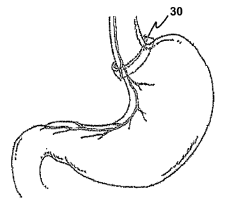
[0046] Figure 6 is a simplified partial front view of the human stomach
showing the cardia,
fundus, body, antrum and pylorus regions and showing typical branching of the
left vagus nerve on
the anterior surface of the stomach.
[0047] Figures 7, 8 and 9 are simplified front views of the human stomach
illustrating three
exemplary placement locations for gastric bands that include stimulation
elements and sensors, in
accordance with representative embodiments of the present invention. In Figure
7 the band
encircles the lower esophagus/upper cardia. In Figure 8 the band encircles the
central cardia
region. In Figure 9 the band spans the lower cardia and fundus regions, and
encompasses the
uppermost portion of the body of the stomach.
11
CA 02606000 2007-10-23
WO 2006/118793 PCT/US2006/014690
DETAILED DESCRIPTION OF THE PREFERRED EMBODIMENTS
[0048] The following description and examples are offered by way of
illustration, and not by way
of limitation. Persons of skill in the art will recognize that many variations
of the exemplified
embodiments can be made, especially in light of the teachings of the various
references cited
herein, the disclosures of which are hereby incorporated by reference herein.
[0049] Systems of the present invention generally comprise a gastric band for
encircling a region
of the gastrointestinal tract, preferably at or near the cardia of the
stomach, and an implantable
neuromodulation controller comprising one or more implantable sub-units
capable of modulating
electrical activity on a vagus nerve of the patient and/or changing a
constriction applied to a gastric
structure. An external programming unit or programming module is also
preferably included. The
term "gastric band" is intended to include bands that are capable of looping
around or encircling at
least a portion of the lower esophagus, cardia, esophageal-cardia junction,
cardia-fundus junction
or upper portion of the stomach (i.e., areas that are innervated by the left
or right vagus nerves or
branches thereof) for restricting the volume of one or more of the
aforementioned structures. In
one embodiment, the external programming unit comprises a processor capable of
receiving sensed
information from the implantable stimulation controller, analyzing the
information, and developing
or changing a therapeutic algorithm to provide regulatory signals or
programming to one or more
of the stimulation units of the implantable stimulation controller.
[0050] Band 30 is preferably capable of forming an adjustable loop around an
esophageal/upper
stomach area. The band may be adjusted in circumference so as to constrict the
diameter of the
encircled area, thereby creating a small gastric pouch to limit and control
the amount of food that is
eaten, and slowing the emptying process from the stomach into the intestines
by creating a smaller
entrance (stoma) to the body of the stomach. After band 30 is carefully
positioned, the diameter is
adjusted, and the band is preferably fixed to the outside of the stomach wall
to prevent migration.
This may be accomplished by sutures or by using another suitable technique or
fixation device as is
known in this field for securing conventional gastric bands. When band 30 is
properly placed for
treating an eating disorder, the therapeutic operation of assembly 1 should
not appreciably alter
normal peristalsis, and should not provoke vomiting or a sensation of gagging
or choking in the
patient. In one embodiment, the vagus nerve is stinlulated to reduce the
patient's appetite and/or
desire to eat as a treatment for obesity. In another embodiment, the vagus
nerve is stimulated to
reduce purging behavior and thereby treat bulimia.
[0051] New treatment systems for obese patients may comprise gastric
constriction combined with
one or more of three different modalities for modulating electrical activity
on the vagus/gastric
nerves of the lower esophagus and upper stomach, i.e., an electrical mode, a
mechanical mode and
a chemical mode. In the representative assembly schematically illustrated in
Figure 1, all three
12
CA 02606000 2007-10-23
WO 2006/118793 PCT/US2006/014690
modulation modalities are shown to provide one, two or all three types or
modes of vagus nerve
stimuli at one or more application sites within a single treatment area (i.e.,
tissue surrounded by a
gastric band). The treatment assembly may be programmed to operate any one of
the stimulation
modalities alone, or in any combination of modalities, either independently or
in concert, in
accordance with the particular needs of the patient.
[0052] In treatment system employing electrical modulation of the vagus nerve,
new methods to
determine which electrodes from among a plurality of electrodes should be used
to provide the
electrical stimulation signal. In particular, sensing electrodes may be
employed in combination
with stimulating electrodes to identify which of the stimulating electrodes
induce the largest action
potential signal on one or both of the anterior and posterior vagus nerves.
Several algorithms may
be employed to identify which of the stimulating electrodes provide the most
effective modulation
of the vagus nerve.
[0053] Certain embodiments of the present invention also permit noninvasive,
in situ adjustment
of a gastric band by an external band adjustment controller after the band is
implanted in the body
of the patient. Such a band allows a healthcare provider or the patient to
post-operatively and
noninvasively adjust the gastric restriction provided by the band as needed or
desired, without
further surgical intervention into the body of the patient. In one embodiment,
the band is
automatically adjusted according to a treatment algorithm to maintain a
relatively constant pressure
on a gastric structure, without the need for intervention form a healthcare
provider. Figure 1 also
depicts a band adjustment controller and fluid reservoir for adjusting the
degree of constriction
provided by the gastric band.
[0054] Referring to Figure 1, treatment system 1 for treating an obese person
comprises a gastric
band 30 and an implantable system controller 2 which comprises a number of
modulation sub-units,
including a pulse generator 4, a mechanical modulation controller 5, a
chemical modulation
controller 6, and a band adjustment controller 7. A group 19 of
interconnecting electrical leads 20,
22 and tubes 24, 26 couples the sub-units of system controller 2 to band 30.
One or more power
supplies (not shown), such as a conventional long-lasting implantable medical
device battery, or set
of batteries, is preferably included in stimulation controller 2, for powering
the sub-controllers 4, 5,
6 and 7. A fluid reservoir 12 is provided for adjusting the constriction of
the band 30 on the
esophagus and/or stomach. Reservoir 12 is coupled to band adjustment
controller 7 by a conduit or
tube 15. A chemical reservoir 16 is available for providing chemical
stimulation, coupled to
chemical controller 8 by conduit or tube 17. An external programming unit 10
is provided for
programming and receiving data from the system controller (or sub-units
thereof). Gastric band 30
comprises an inner surface 33 for surrounding and contacting an outer surface
of the stomach or
esophagus. Electrodes (for electrical stimulation and sensing), vibration
elements (for mechanical
13
CA 02606000 2007-10-23
WO 2006/118793 PCT/US2006/014690
stimulation), and outlet ports (for chemical stimulation) are coupled to
gastric band 30, preferably
on inner surface 33.
[0055] It will be appreciated that body 32 of band 30 is illustrated in Figure
1 in a simplified,
schematic form, and that many known gastric band designs can be readily
modified to provide a
band 30 suitable for use in the present invention. When closed to form a loop
(which may be a
complete loop or a partial loop) around an area of the lower esophagus and/or
upper stomach
region, the circumference of body 32 is preferably capable of being post-
operatively and non-
invasively adjusted in situ, as described more fully hereinafter. Band 30 may
be implanted and
removed during either open or, more preferably, minimally invasive surgical
procedures (e.g.,
laparoscopically). Body 32 is preferably flexible and in a preferred
embodiment comprises
silicone. However, any suitable known gastroplasty band design may be adapted
for use as band
30. One such design is a conventional LAP-BANDO, commercially available from
Inamed
Health, Santa Barbara, CA. Other examples of adaptable band designs are those
described in U.S.
Pat. App. Pub. No. 2003/0208212 and U.S. Pat. No. 6,102,922, the disclosures
of which are hereby
incorporated herein by reference.
[0056] Although one or more of the electrical, mechanical, and chemical modes
of modulation of
the vagus nerve may be omitted, it is preferred that systems of the present
invention comprise at
least electrical stimulation via pulse generator 4, which comprises an
electrical stimulation
controller. An embodiment of the present invention providing only electrical
modulation of the
vagus nerve is shown in Figure 2. Pulse generator 4 comprises an electronics
package for
generating an electrical output signal, preferably in the form of a sequence
of pulses, with parameter
values programmable within predetermined ranges for treating a patient having
an eating disorder.
A lead 20 is coupled at a proximal end to the generator 4 and at a distal end
to connector 21, and
delivers a programmed stimulating signal to the patient's vagus/gastric
nerve(s) via stimulation
electrode(s) 36. The pulse generator is preferably also capable of receiving a
signal indicative of
sensed or detected nerve voltage transients from sensing electrodes 28 on band
30, and to process
that signal according to suitable sensing and therapy algorithms stored in a
memory. The therapy
algorithm is programmed by the clinician who sets the stimulation parameters
of pulse generator 4.
[0057] A pulse generator suitable for use in the invention is available from
Cyberonics, Inc.,
Houston, Texas, as the Model 102 generator. Referring again to Figure 2, inner
surface 33 of band
30 comprises at least one, and preferably a plurality, of stimulating
electrode(s) 36 for electrical
stimulation of a vagus nerve or nerve branch (gastric nerve) on an exterior
surface of the esophagus
or stomach. As shown in Figure 2, electrodes 36 preferably comprise a
plurality of electrode pairs
36a, 36b, which function as cathode and anode, respectively, in delivering the
electrical stimulation
signal to the vagus nerve(s) of the patient. Stimulation electrodes 36 may be
embedded in body 32
14
CA 02606000 2007-10-23
WO 2006/118793 PCT/US2006/014690
of band 30 or, more preferably, may be coupled to inner surface 33 thereof. In
certain
embodiments, only stimulation electrodes may be provided. In other
embodiments, one or more
sensing electrodes 28 may also be provided on inner surface 33. As with
stimulation electrodes 36,
sensing electrodes 28 preferably comprise a plurality of electrode pairs 28a,
28b.
[0058] Stimulation electrodes 36 preferably deliver electrical stimulation to
a nerve structure such
as the vagus nerve, and sensing electrodes 28 may sense voltage activity
fluctuations on a nerve
(e.g., action potentials traveling afferently and/or efferently) in response
to a stimulus such as an
electrical pulse from electrodes 36. Stimulating electrodes 36 allow a train
of electrical pulses to
be delivered to tissue (preferably nerve tissue) in electrical contact with
the electrodes. Stimulation
is provided according to programmed parameters of, e.g., pulse width, current
magnitude,
frequency, and duty cycle or on/off time. Additional details of stimulation
parameters are
disclosed in US patent Nos. 5,188,104, 5,263,480, 6,587,719, 6,609,025, all
hereby incorporated by
reference. Sensing electrodes send an electrical signal representative of the
response to the pulse
generator 4, as will be further described below.
[0059] When electrodes 28 are placed immediately adjacent stimulation
electrodes 36, there is a
risk that electrical charge migration or leakage from stimulation electrodes
36 will result in sensing
electrodes 28 detecting the stimulation signal itself, rather than the action
potentials induced on the
vagus nerve by the signal. To minimize this risk, it is preferred that sensing
electrodes 28 and
stimulating electrodes 36 be located near the ends of the upper (superior) and
lower (inferior) edges
of band 36, respectively. It is preferred that sensing electrodes 28 be
located nearer to on the upper
edge of band 30. Locating sensing electrodes 28 above the stimulating
electrodes 36 serves both to
minimize the strength of any current leakage from stimulating electrodes 36,
and also facilitates
detection of afferent action potentials on the vagus nerve induced by the
stimulating electrodes 36.
[0060] As depicted in Figure 2, band 30 preferably comprises a lead connector
21 for electrically
coupling leads 20 with to the stimulating electrodes 36 and/or nerve sensing
electrodes 28.
Preferably, an independent electrical path is provided to each of the stimulus
electrodes 36 and
sensing electrodes 28, for example by a multiaxial cable or a separate wire
for each electrode.
Internal electrode selection circuitry in pulse generator 4 may be provided to
permit each electrode
36, 28 to be independently selected for stimulation by pulse generator 4. In
an alternate
embodiment, the selection circuitry may be provided in band 30, allowing a
reduction in the
number of electrical paths that must be provided by leads 20. However
implemented, the circuitry
preferably allows any of stimulating electrodes 36 to be independently
selected for stimulation, and
any of sensing electrodes 28 to be independently selected for sensing. In one
embodiment, the
circuitry comprises a multiplexer and one or more address registers (not
shown) to allow pulse
generator 4 to select particular electrode(s) 36, 28 from among the plurality
of electrodes for
CA 02606000 2007-10-23
WO 2006/118793 PCT/US2006/014690
stimulating or sensing, respectively. Each electrode 36, 28 may alternatively
be coupled to a
separate lead connector (e.g., connector 21A, 21B, . . . , 21i, not shown) and
lead (e.g., 20A, 20B, .
.., 20i, not shown). Techniques to allow selection of specific electrodes
and/or sensors from
among a plurality of stimulation and/or sensing electrodes are known in the
art.
[0061] Referring to Figure 3, mechanical stimulation of the vagus nerve is
provided by mechanical
stimulation controller 6. Band 30 may also comprise one or more mechanical
stimulation elements
34 on the inner surface 33 of band 30. A connector 23 is provided on band 30
for electrically
coupling leads 22 and mechanical stimulation elements 34, which may comprise a
piezoelectric
vibrator element embedded in body 32 of band 30, a pressure transducer, or a
displacement
transducer, although a piezoelectric vibrator element is preferred. The
vibrator element may
deliver mechanical stimulation to a vagus nerve by vibrating in a pulsatile
manner at a controlled
frequency, energy amount delivered per unit time (pulse amplitude), and on/off
time (pulse period).
Mechanical stimulation elements 34, whether comprising a vibrator element or a
different type of
stimulation element, apply mechanical pressure to the vagus nerve at a desired
frequency in
response to a signal from pressure controller 6. Like electrical stimulation,
previously described,
mechanical stimulation may be used to generate action potentials on the vagus
nerve, the afferent
components of which travel to the brain to treat the patient's eating
disorder.
[0062] Referring again to Figure 3, leads 22 preferably provide an independent
electrical path to
each of the mechanical stimulation elements 34, either by a multiaxial cable
or a separate wire for
each element. Additionally, mechanical stimulation controller 6 also
preferably includes selection
circuitry to allow the controller 6 to individually select desired stimulation
element(s) 34 from
among a plurality of such elements for modulation of the vagus nerve.
Techniques, such as
multiplexing and registers storing addressable stimulation leads, that allow
for the selection of
specific elements from among a plurality of elements, are known in the art. In
less preferred
embodiments, the selection circuitry may be provided in band 30, and
mechanical stimulation
elements 34 may all be addressed and energized simultaneously.
[0063] In a third mode of providing neurostimulation, embodiments of the
present invention may
also provide chemical stimulation to suppress appetite. Referring to Figure 4,
a chemical controller
8, in conjunction with chemical reservoir 16, may provide chemical stimulation
of the vagus nerve.
In this embodiment, band 30 is provided with one or more chemical outlet ports
38 on band 30.
Controller 8, which preferably comprises a pump, delivers a chemical
stimulation agent from
reservoir 16 to outlet ports 38. Each outlet port 38 may coniprise a valve or
pierceable seal (not
shown) that prevents the chemical from diffusing or flowing out without
operation of the pump or
other flow delivery means (e.g., a syringe). A chemical inlet line 26 provides
communication
between chemical controller 8 and band 30 via a connector 27, which is in turn
in communication
16
CA 02606000 2007-10-23
WO 2006/118793 PCT/US2006/014690
with chemical outlet ports 38. Reservoir 16 is coupled to controller 8 by a
conduit or tube 17, and
may comprise an implantable reservoir that may be refilled by percutaneous
injection via an access
port 18. Alternatively, access port 18 may permit delivery of a removable
catheter reservoir
containing the agent. Such a reservoir may be periodically delivered, used,
removed, and replaced
by a fresh catheter. Suitable pumping or controlled release devices which may
be adapted for use
as chemical pump 8 are disclosed in U.S. patent Nos. 6,571,125 and 6,356,784,
both assigned to
Medtronic, Inc. Chemical controller 8 may include a receiver for receiving and
processing a
transcutaneous electromagnetic signal (e.g., RF signal) and a signal converter
for directly causing a
pump to move the agent from reservoir 16 to outlet(s) 38 in response to an
externally applied
electromagnetic signal.
[0064] In an alternative embodiment, chemical controller 8, reservoir 16,
access port 18, and outlet
ports 38 may be omitted and instead the body 32 of band 30 may comprise, or be
coated with, a
chemical-eluting material such as a polymer matrix (not shown) containing a
chemical agent, such
as a drug or antibiotic, for treating a particular patient, preferably by
stimulating a vagus
nerve. For instance, the chemical/matrix coating may be made to elute the
chemical agent over a
desired period of time after implantation. Known degradation rates of various
degradable
polymers may be used to provide a polymer matrix having a desired elution
profile for a particular
chemical agent. Polymer matrices suitable for use in delivering one or more
chemical agents may
comprise one or more biodegradable polymers such as polylactic acids,
polyglycolic acids and
other polyhydroxy acids, polycaprolactone, and other slowly degrading
polymers, or may comprise
biostable polymers such as polyurethanes, silicones, acrylates, polyesters,
polyethylene oxides,
polyalcohols, and polyolefins, by way of nonlimiting example. Other
biodegradable and biostable
matrix materials are well-known in the art, and it will be appreciated that
any suitable controlled-
release chemical-eluting material could be substituted. More generally, the
placement of
electrodes, sensors, pressure applicators, chemical outlets and connectors may
be varied, and the
appearance of the gastric band may differ from those shown in Figures 1-4
without negatively
affecting the operation of the assembly.
[0065] In addition to providing nerve stimulation capability, gastric band
systems of the present
invention also preferably provide the capability of post-operatively and non-
invasively adjusting
the circumference of band 30 around the esophagus/stomach, thereby altering
the degree of
constriction that band 30 provides to the patient's gastric system. In current
gastric band systems,
the physician typically adjusts the constriction of the band during surgery by
inflating one or more
expansion members with a hydraulic fluid to provide a fixed degree of
constriction, which can only
be changed with further surgical intervention or invasively by percutaneously
inserting a needle
into an implanted reservoir to add or withdraw hydraulic fluid from the band.
In either of the
17
CA 02606000 2007-10-23
WO 2006/118793 PCT/US2006/014690
current ways of post-operatively adjusting the band, the patient is subjected
to a painful and
potentially dangerous process. In systems of the present invention, by
contrast, post-operative
changes in constriction can be made non-invasively whenever desired by
commands from an
external programming unit.
[0066] An embodiment of a post-operatively adjustable gastric band is shown in
Figure 5. In
general, a band adjustment controller 7 may be used to control a constriction
adjustment element
coupled to band 30. The band adjustment controller may be actuated or
programmed by external
programming system 10, allowing post-operative, in situ adjustments to the
band's constriction
upon the patient's gastrointestinal tract. The constriction adjustment element
increases or
decreases the level of constriction of the gastrointestinal tract under the
control of the band
adjustment controller, facilitating therapy regimes previously impossible in
prior art gastric bands.
In one embodiment, the constriction adjustment element comprises one or more
expansion
members that may be inflated or deflated by adding or removing a hydraulic
fluid from the
expansion members. In other embodiments, the adjustment element comprises a
mechanical
adjustment system such as a radiator clamp-type belt and a screw or worm gear
adjustment, a rack-
and-pinion adjustment system, or other mechanical devices for adjusting a
circumferential member.
[0067] Referring to Figure 5, the system 1 is provided with a reservoir 12
containing a hydraulic
fluid, such as mineral oil, saline or other biologically compatible fluid.
Reservoir 12 may also
include a sensor (not shown) to indicate when the reservoir is low or empty. A
fluid reservoir
access port 14 may optionally be provided to allow hydraulic fluid to be added
to or removed from
the system after the system 1 is implanted. The access port preferably
comprises a self-sealing
membrane into which a needle may be inserted transcutaneously to add or
withdraw fluid from the
reservoir 12. The fluid may be delivered by band adjustment controller 7 from
reservoir 12, via
fluid line 24, to inflate one or more expansion members (not shown)
incorporated in band 30. The
expansion members may be located within body 32, or coupled to a surface of
barid 30. In one
embodiment, one or more hollow chambers are provided in body 32 to function as
the expansion
member. In another embodiment, one or more balloon members may be coupled to
inner surface
33 of band 30. By inflating the expansion members, the degree of constriction
of the
esophagus/stomach is increased. Constriction may be reduced by removing the
hydraulic fluid
from the expansion members and returning it to reservoir 12. A connector 25
couples fluid line 24
to band 30 and the expansion members. Band adjustment controller 7 may include
a receiver for a
transcutaneous electromagnetic signal (e.g., RF signal) and control logic or
circuitry implementing
a treatment algorithm for directly causing a fluid pressure change in band 30
in response to an
externally applied electromagnetic signal.
18
CA 02606000 2007-10-23
WO 2006/118793 PCT/US2006/014690
[00681 It is desirable that the treatment system 1 also include the ability to
determine and report to
an external user an indication of how much restriction has been provided by
the adjustment
element. The band adjustment controller 6 preferably provides a constriction
indication signal,
which allows a healthcare provider to precisely adjust or alter the therapy
provided to the patient.
The constriction indication signal may be transmitted wirelessly to external
programmer 10 upon
inquiry, and the external programmer 10 preferably provides a graphical or
other visual indication
of the degree of constriction to the healthcare provider. In a preferred
embodiment, band
adjustment controller 7 comprises a reversible pump (not shown) capable of
pumping fluid either
from the reservoir to the expansion members or from the expansion members back
to the reservoir.
In this embodiment, a constriction indication may be provided by calibration
circuitry in the band
adjustment controller. The calibration circuitry is coupled to the reversible
pump to indicate how
much fluid has been pumped into the expansion members at any given point in
time. In one
embodiment the reading may comprise a numerical percentage indication, from 0%
to 100%, of
how much fluid relative to its maximuin capacity has been added to the
expansion members.
[00691 In another embodiment, the constriction indication signal may be
provided by
incorporating one or more pressure sensors 35 on band 30 to sense the degree
of constriction
provided by the band. As the band tightens around the esophagus/stomach, the
increased pressure
sensed by the pressure sensors provides a signal that corresponds to the
increased constriction.
Calibration circuitry in the band adjustment controller uses the electrical
signals from the pressure
sensors to provide a constriction indication signal, which may correspond to a
numerical
designation from 0-10 to indicate the relative degree of constriction, with
zero indicating no
constriction and ten indicating a maximum constriction setting consistent with
patient safety. The
pressure sensors 35 may comprise electrodes positioned on the inside surface
33 of band 30, and
may be coupled to band adjustment controller 7 by a lead (not shown) similar
to lead 20 for pulse
generator 4. The pressure signal from sensors 35 may then be used as a
constriction indication
signal directly by band adjustment controller 7, which may comprise a
treatment algorithm in
which the constriction is altered according to a predetermined schedule.
Alternatively, the signal
may be transmitted to the external programmer 10 and the constriction
displayed to the healthcare
provided, who may then add or withdraw fluid to or from the expansion
member(s) of band 30 and
thereby change the degree of esophagus/stomach constriction as desired. The
pressure sensors
may alternatively comprise a fluid pressure sensor (not shown) within the
expansion members. It
will be appreciated, however, that any suitable pressure sensing device known
may be incorporated
into band 30 and used with calibration circuitry to provide a constriction
indication.
[00701 In a further embodiment, pressure sensors 35 may be used to provide a
relatively constant
pressure on the esophagus/stomach. One or more of sensors 35 may provide
pressure indications
19
CA 02606000 2007-10-23
WO 2006/118793 PCT/US2006/014690
at a desired sampling rate (e.g., once per second, once per minute, twice per
hour, once per day or
longer). The time series pressure signals may be used by adjustment controller
7 in a treatment
algorithm to add or withdraw fluid from the expansion members so as to
maintain a relatively
constant pressure (as opposed to a constant degree of restriction) on the
esophagus/stomach. The
treatment algorithm may comprise a program executed by control logic. This
embodiment
provides the advantage of allowing the esophagus/stomach to maintain some
degree of its natural
motility, while also providing restriction to prevent the patient from
overeating. Such modes of
treatment are not available in current devices.
[0071] Although mechanical stimulation of the vagus and/or gastric nerves and
branches thereof is
preferably accomplished with vibrator elements, low-frequency stimulation of
the vagus nerve may
also be provided by using band adjustment controller 7, reservoir 12 and tube
24 to provide one or
a series of fluid pulses of defmed frequency, intensity and duration, causing
the band or inflatable
member to take in fluid, inflate or enlarge, and cause constriction or
pressure on vagus nerves
underlying the tissue contacted by band 30 or an inflated portion thereof, and
then withdraw the
fluid to relieve the pressure. This is preferably accomplished during an
initial adjustment
procedure, similar to those described previously, in which the healthcare
provide notes any nausea,
retching, "fullness" sensations, or other indicators associated with certain
fluid pulse parameters.
When the fluid pulse characteristic(s) that produce(s) a selected level of
response in the patient
(e.g., fullness, nausea, retching) are identified, a fluid pulse threshold is
thus obtained, and the
clinician would then adjust the programming of the band adjustment controller
7 to only administer
fluid mediated stimuli that are below that threshold level.
[0072] External programming unit 10 is used to control the operation of each
type of modulation
controller 4, 5, and 6, as well as band adjustment controller 7. External
programming unit 10,
shown in simplified block diagrammatic form in Fig. 1, comprises electronic
circuitry, typically
including a processor, programmable memory, and a display or other data output
device (not
shown). The external programming unit 10 also comprises software that may be
used to program
system controller 2, and more specifically pulse generator 4, mechanical
stimulation controller 5,
chemical stimulation controller 6, and band adjustment controller 7, with
sensing, analytic, therapy,
and/or constriction algorithms appropriate for the particular treatment
regimen desired. System
controller 2 preferably comprises a programmable communications interface
coupled to one or
more of sub-unit controllers 4, 5, 6, and 7. After implantation of system
controller 2, band 30, and
the associated connecting leads and conduits for each respective
modulation/adjustment system
included in the overall system 1, the external programming unit 10 is
preferably capable of wireless
communication with the modulation/adjustment controllers 4, 5, 6, and/or 7 for
conducting
monitoring, diagnostic and programming functions.
CA 02606000 2007-10-23
WO 2006/118793 PCT/US2006/014690
[0073] Programming unit 10 is also preferably structured to provide user
interface functions, e.g.,
straightforward, menu-driven operation, "help" functions, prompts, and
messages to facilitate
simple and rapid programming and programming modifications, and displaying or
reporting
desired data and events relating to the stimulation/adjustment controllers 4-
7. The programming
capabilities preferably allow modification of the programming of the
stimulation/adjustment units
to set or change adjustable parameters and to test device diagnostics.
External programming
system 10 is preferably also capable of receiving signals from the stimulation
units corresponding
to data such as parameter settings on the respective stimulation units 4, 5,
or 6, or the current
restriction status/setting for band 30.
[0074] The external programming unit 10 may be used to program the system
controller 2 to
operate any one of the stimulation modalities alone, or any combination of
those modalities, either
independently or in concert. Thus, a useful treatment system may omit one or
two of the three
modalities. For instance, the capability for chemical stimulation of the vagus
nerve may be
eliminated by omission of chemical controller 6, reservoir 16, tube 26,
connector 27, and outlets 38
(and any chemical eluting matrix). Similarly, the capability for mechanical
stimulation may be
eliminated by omission of mechanical modulation controller 5, reservoir 12,
lead 22, connector 23,
and mechanical modulation elements 34. Another alternative configuration could
omit the
electrical pulse generator 4, lead 20, connector 21, and stimulation and
sensing electrodes 36, 28 if
electrical stimulation or nerve sensing will not be employed.
[0075] Other capabilities of the prograimning and electronic circuitry of
external programming
unit 10 and various components of control system 2 may include the capability
to store and retrieve
historical data. For example, patient code, device serial number, number of
hours of battery
operation, number of hours of stimulation output, and number of manual
activations (indicating
patient intercession) for display on a screen with information showing date
and time of the last one
or more activations.
[0076] The overall treatment system, which preferably includes implantable
components and
external programming components, is preferably noninvasively calibrated for a
particular patient by
telemetry from the external programming unit 10. The implanted electronics
package may be
externally programmed for activation upon occurrence of a predetermined
detectable event (such as
nerve activity detected by sensors 28), or may be periodically or continuously
activated according
to a programmed duty cycle, to generate the desired stimulation signal, which
is applied to the
patient's anterior and/or posterior vagus nerves, or branches thereof, to
modulate vagal activity to
treat an eating disorder, e.g., treating obesity by reducing appetite or
producing a feeling of satiety.
[0077] External programming unit 10 is preferably capable of wireless
communication with any of
the sub-unit controllers 4, 5, 6 and 7, as designated by line 11 in Figure 1.
Details for such
21
CA 02606000 2007-10-23
WO 2006/118793 PCT/US2006/014690
communication are known in the art. More specifically, external programming
system 10 is
capable of communicating transcutaneously with at least pulse generator 4 of
system controller 2
via transmission and reception of electromagnetic signals (e.g.,
radiofrequency signals (RF)).
Alternatively, a percutaneous lead (not shown), may be used as communication
path 11. However,
wireless communication minimizes the risk of potential infection by avoiding a
path from outside
the body to the abdominal cavity along the lead.
Positioning and Adjusting the Treatment Assembly.
[0078] Figure 6 illustrates in a simplified manner the lower esophagus and the
cardia, fundus,
body, antrum, pylorus and duodenum regions of the human stomach, and the
primary vagal/gastric
nerve branches along the anterior surface of the stomach. Figures 7, 8 and 9
are simplified front
views of the stomach showing a range of representative placement locations for
gastric bands with
vagus nerve modulation capability. Electronic components are not shown in
Figures 7-9 to
enhance the clarity of the placement locations depicted. In Figure 7, the band
encircles the lower
esophagus/upper cardia. In Figure 8 the band encircles the central cardia
region. In Figure 9 the
band spans the lower cardia and fundus regions, and encompasses the uppermost
portion of the
body of the stomach.
[0079] The exact placement of the band may vary from the positions shown in
Figures 7-9, in
accordance with the healthcare provider's judgment with respect to the
particular patient being
treated. In embodiments involving neuromodulation, at least one stimulation
controller must be
included to provide a stimulation signal or agent to band 30 in operational
relation to at least one
vagus nerve or gastric vagal branch, i.e., in a manner that is effective for
reducing the patient's
appetite or inducing a feeling of satiety when assembly 1 is operated to
stimulate the nerve or nerve
branch. For optimally sensing a nerve response, and/or for optimally applying
electrical pulses to
a nerve, one or more nerve sensing electrodes 28 or stimulating electrodes 36
on band 30 is
preferably positioned directly over a vagal/gastric nerve or nerve branch.
[0080] Systems of the present invention may be implanted by a number of
surgical procedures,
such as open or closed laparotomy or thoracotomy. Minimally invasive
procedures are preferred to
facilitate patient recovery and to minimize scar tissue formation. During the
same surgical
procedure in which band 30 is coupled to the patient's esophagus/stomach
region, controller 2
(depicted in Figures 1-5) is also implanted in the patient's body, preferably
in the abdominal region
below diaphragm 42; for example, via a left laparotomy incision. Lead 20
(electrical modulation),
lead 22 (mechanical modulation), tubes 17 and 26 and chemical reservoir 16
(chemical
modulation), and tubes 15 and 24, and pressure fluid reservoir 12 (band
adjustment) are also
implanted during the procedure. The leads and tubes are connected as shown in
Figures 1-5. The
fluid reservoir access port 14 is preferably placed below the skin below the
rib cage to allow for
22
CA 02606000 2007-10-23
WO 2006/118793 PCT/US2006/014690
fluid to be injected, e.g., by a needle percutaneously inserted into reservoir
12 via port
14. Similarly, the chemical access port 18 may be located below the skin below
the rib cage to
allow for ease of filling or emptying of the reservoir 16 via port 18.
[0081] Reservoirs 12 and 16 are preferably filled in advance of surgery, with
the desired pressure
fluid or chemical solution, respectively, and may also be filled (or refilled)
in situ via ports 14 and
18 after implantation of the reservoirs. Alternatively, in instances in which
one or both of chemical
controller 6 and band adjustment controller 7 are omitted from system
controller 2, application of a
chemical agent (e.g., an antibiotic) via outlet(s) 38 and/or inflation of
expansion members coupled
to band 30 may be manually effected, respectively, by injecting or withdrawing
chemical solution
or hydraulic fluid via ports 14 and/or 18.
[0082] Programming methods known in the art for neurostimulators may be used
to program
system controllers 2 and/or sub-controllers 4, 5, 6, and 7. For embodiments
employing electrical
modulation, pulse generator 4 may be programmed by a healthcare provider,
preferably by
telemetry (e.g., using an RF programming wand) in communication with external
programming
unit 10. The healthcare provider may also run one or more diagnostic
procedures on pulse
generator 4, and/or receive data from the generator.
[0083] An initialization program, which may be stored either in the external
communication unit
or in the pulse generator 4, is preferably executed at the time the iniplant
is first programmed
after implantation. The initialization program is used to determine which
stimulating electrodes 36
and which sensing electrodes 28 are nearest one or both of the anterior and
posterior vagus nerves.
Electrical stimulation and sensing of the vagus nerve requires that the
electrodes be either in direct
contact with the vagus nerve or are in close proximity thereto. Accordingly,
in preferred
embodiments only the stimulating electrode(s) 36 and sensing electrode(s) 28
that are nearest the
vagus nerve are used to stimulate and sense the nerve, since energizing all of
the stimulating and
sensing electrodes simply depletes the battery of the pulse generator 4 with
no corresponding
benefit to the patient.
[0084] A number of initialization processes may be used to determine the
electrodes 36, 28 nearest
to the anterior and/or posterior vagus nerves. Algorithms for the
initialization processes are
preferably maintained in a memory, and executed by an initialization
controller, in pulse generator
4. In whatever procedure is used, the surgeon must first secure band 30 to the
esophagus/stomach.
After the band is attached to the GI tract it is unknown, prior to
initialization, which sensing and
stimulating electrodes are located nearest to the vagus nerve(s) and thus are
the best electrodes for
delivering the electrical stimulation to the nerve. However, by sequentially
energizing one or more
stimulating and sensing electrodes, it is possible to determine which
stimulating and sensing
electrodes are located nearest the anterior and/or posterior vagi.
23
CA 02606000 2007-10-23
WO 2006/118793 PCT/US2006/014690
[0085] In one initialization process, all of the stimulating electrodes 36 are
simultaneously
energized in a series of pulses, and individual sensing electrodes are
sequentially used during
and/or immediately after each of the stimulation pulses in an attempt to
detect an action potential
on the vagus nerve induced by the stimulating electrodes. The parameters used
for the
initialization stimulating pulses are set so as to reliably generate an action
potential on the nerve,
i.e., the pulses have a relatively high amplitude such as 6 microamperes, and
have a relatively long
pulse width such as 1.0 milliseconds. The timing sequence for energizing the
sensing electrode(s)
relative to the stimulation electrodes may be varied across a wide spectrum
with acceptable results.
In one embodiment, the sensing electrodes may be energized simultaneously with
the stimulating
electrodes, and for the same duration. In another embodiment, the sensing
electrodes may be
energized slightly after the leading edge of the stimulation pulse (e.g., with
a delay of 100
microseconds) and the sensing pulse may extend for a period slightly beyond
the stimulating pulse
to ensure that any action potentials generated near the end of the stimulation
pulse are sensed.
[0086] In a preferred embodiment, for each of the stimulation pulses
energizing all of the
stimulation electrodes, one (and only one) of the sensing electrodes 28 (which
preferably
comprises an electrode pair adapted to sense activity at a particular location
on the inner surface 33
of the band 30) is correspondingly energized to determine whether'or not the
stimulation pulse
produced a voltage transient indicative of an induced action potential. If
such a voltage transient is
detected, the address of the sensing electrode and the magnitude of the action
potential measured
are noted. After the first stimulation and sensing pulses, a second
stimulation pulse is made, and a
second sensing electrode is used to sense any voltage transients corresponding
to induced action
potentials. As with the first pulse, if a voltage transient is detected, the
address of the sensing
electrode and the magnitude of the action potential measured are noted.
Additional stimulating and
sensing steps are performed until all of the sensing electrodes have been
used, with any detected
voltage transients recorded along with the address of the sensing electrodes.
[0087] After all of the sensing electrodes have been used to detect induced
action potentials, the
electrodes detecting the largest magnitude pulses are determined by comparing
the detected voltage
magnitudes. The electrodes having the highest detected voltage magnitudes will
be the electrodes
nearest to the anterior and posterior vagus nerves. Depending upon the
location of the electrodes
relative to the vagus nerves, it is believed that one or two of the sensing
electrodes will have
significantly higher voltage magnitudes for each branch of the vagus nerve,
indicating that those
electrodes are closest to the vagus nerve. In preferred embodiments, once the
locations of the
vagus nerve branches are known, the stimulating electrodes 36 that are
adjacent to the sensing
electrodes nearest to the nerves are thereafter the only electrodes used for
stimulation. These
stimulating electrodes can be determined from the known addresses of the
stimulating electrodes
24
CA 02606000 2007-10-23
WO 2006/118793 PCT/US2006/014690
and their positions relative to the sensing electrodes nearest to the vagus
nerves. It will be
understood that, although the process has been described using only a single
sensing pulse to test
the response of each sensing electrode, a plurality of pulses may also be used
to confirm that the
electrode does (or does not) lie adjacent to a branch of the vagus nerve.
[0088] In another embodiment, individual stimulation electrodes (instead of
all of the stimulation
electrodes) are individually and sequentially energized with electrical pulses
of sufficient
magnitude to generate an action potential on the vagus nerve if the electrode
is either in direct
contact or closely adjacent to the nerve. Preferably, a plurality of pulses
are provided to the
electrode to allow the detection (or non-detection) of the action potential to
be confirmed by
repeated stimulation and detection steps. In this embodiment, a single
stimulation electrode
delivers one or more electrical pulses, and one or more sensing electrodes are
used to sense any
induced action potentials. In this embodiment, it is preferred that all of the
sensing electrode pairs
may simultaneously be used to detect an induced action potential, and the
magnitude and location
of any sensed voltage fluctuation is to be noted. Alternatively, for each
individual stimulation
electrode, several of the electrodes nears to the stimulation electrode may be
used, individually and
sequentially, to detect any induced action potential. This approach provides a
more detailed view
of which electrodes are near the vagus nerve, but may take a longer time to
perform because more
combinations must be tested. Regardless of whether all or only a portion of
the sensing electrodes
are used, the sensing step should be timed relative to the stimulation test
pulse according to a
timing designed to reliably detect any action potential induced by the
stimulating pulse. In one
embodiment, the sensing electrode is energized at the start of the stimulation
pulse and the sensing
pulse continues for a period of time, e.g., 100 microseconds, after the
stimulation pulse has ended.
In another embodiment, the stimulation pulse begins slightly after the
stimulation pulse, e.g., 50
microseconds, and is discontinued at the same time as the stimulation pulse.
Because the goal is
simply detection of a large signal, the timing is not critical, and persons of
skill in the art may
readily arrive at suitable timing parameters for the stimulation and sensing
pulses to enable the
sensing electrode to determine whether or not the stimulating electrode has
induced an action
potential on the vagus nerve.
[0089] If the sensing and stimulating electrodes are adjacent to one of the
branches of the vagus
nerve, the sensing electrode will detect a voltage transient associated with
an action potential
generated by the stimulation electrode. If one or both of the stimulating and
sensing electrodes are
not in contact with or adjacent to the vagus nerve, no transient will be
detected. In either case, the
magnitude of the voltage across the sensing electrode is recorded.
[0090] Subsequent stimulation therapy may then use only those stimulation
electrodes identified
in the initialization process as closest to the vagus nerve, avoiding
unnecessary energy expenditure
CA 02606000 2007-10-23
WO 2006/118793 PCT/US2006/014690
associated with energizing electrodes having no effect on the vagus nerve.
Thus, after determining
which electrodes and sensors provide satisfactory, preferably optimal, stimuli
or responses, the
programming in pulse generator 4 preferably comprises additional electrode
lockout software to
automatically use only the stimulation and sensing electrodes identified in
the initialization routine
in subsequent stimulation therapy. The program may be re-executed at the
direction of a
healthcare provider if, for example, the band 30 moves relative to the
esophagus/stomach or vagus
nerve such that the stimulating and sensing electrodes 36, 28 are no longer in
direct contact with
(or closely adjacent to) the vagus nerve. Alternatively, software may
automatically re-initialize the
electrodes at a desired interval, which may range from once each day to once
per month, once per
year, or longer.
[0091] After the electrode initialization procedure is executed, therapeutic
diagnostic procedures
following the initial implant may then continue with the health care provider
administering via the
selected stimulation electrodes and pulse generator 4 a series of electrical
pulses of known voltage,
frequency, pulse width, and duty cycle. The provider notes any feelings
reported by the patient of
nausea, retching response, "fullness" sensation or pain associated with
certain pulse
parameters. For example, if the vagus nerve is stimulated excessively, in one
embodiment
characterized by a current amplitude that is too high, a retching response
typically occurs. When
the pulse characteristic(s) that produce a selected level of response in the
patient (e.g., nausea,
retching, satiety, pain) are identified, a pulse threshold is thus obtained,
and the health care
provider would then adjust the programming of the pulse generator 4 to only
administer stimuli
that are below that threshold level. For example, if the therapeutic level of
pulse current is
programmed to a value less than approximately 6 mA, a typical patient will not
experience retching
attributable to vagus nerve stimulation, although variations in response may
occur from one patient
to another. See, e.g., U.S. patent No. 6,609,025 and 6,587,719. In any event,
the maximum
amplitude of the current is preferably adjusted accordingly during the initial
diagnostic procedure
until an absence of retching is observed, and a suitable current amplitude
safety margin is
programmed into the pulse generator.
[0092] The retching threshold may change noticeably with time over a course of
several days after
the pulse generator begins delivering therapy to the patient. Accordingly, the
therapeutic
diagnostic test is preferably checked again after implantation, especially
during the first few days
after implantation to determine whether any adjustment is necessary to
maintain an effective
therapeutic regimen. Preferably any adjustments in programming that are
necessary after the
implantation procedure and initial setup are made via telemetry. Carrying out
the above-described
customized therapeutic and electrode initialization diagnostics are preferred
because some
differences can be expected from one pulse generator to another due to
idiosyncratic variables in
26
CA 02606000 2007-10-23
WO 2006/118793 PCT/US2006/014690
each treatment situation. For example, differences in the optimum current
magnitude of current in
the stimulation signal pulses may be observed from one patient to another,
which may be
attributable to such factors as patient impedance, anatomical variation in
vagus nerve location and
branching between patients, and variations in electrode/tissue contact from
one implant to another.
Where the stimulation and sensing electrodes directly contact a vagus nerve
branch, lower energy
is necessary for providing effective stimulation, and battery life is
correspondingly lengthened. If,
on the other hand, the stimulation and sensing electrodes are located slightly
off the vagus nerve,
and there is no direct stimulation or sensing, the energy necessary to provide
effective stimulation
will be higher, and battery life will be significantly reduced.
[0093] In systems incorporating mechanical stimulation of the vagus nerve or
branches thereof,
proper placement of band 30 includes ensuring that one or more mechanical
stimulation element 34
is positioned over or sufficiently close to a nerve or nerve branch to cause
action potentials to be
generated on the nerve. Determination of which mechanical stimulation elements
34 should be
used may be accomplished by a procedure similar to that described for
stimulation electrodes 36.
Of course, this can only be done if sensing electrodes 38 are provided on band
30
[0094] Similarly, if chemical stimulation of the target nerve(s) is
incorporated into the system,
one or more chemical outlet 38 on band 30 is operably situated, preferably
over, or in close
proximity to, a target nerve or nerve branch. For instance, a number of spaced
apart chemical
outlets 38 may be arrayed along the inner surface of band 30, however each
comprises a removable
closure or pierceable seal that prevents the chemical from diffusing out.
Identification of which
chemical outlets 38 are nearest to the vagus nerve may not be possible by
processes similar to those
described for identifying which electrodes are nearest to the vagus nerve,
because diffusion of the
agent from the chemical outlets 38 to the vagus nerve cannot be reliably
correlated by sensing
electrodes to distance from the nerve. Accordingly, locating the outlets 38
near the vagus nerve
may be best accomplished by provided visual or other indications for the
surgeon to ensure that
one or more ports can be located generally near the anterior and posterior
vagus nerve branches, as
opposed to a sensing-and-verification process.
[0095] Systems of the present invention may also include diagnostics testing
algorithms to verify
proper operation of the device, and to indicate the existence of problems such
as with
communication, batteries, or lead/electrode impedance. A low battery reading,
for example, would
be indicative of imminent end of life of the battery and need for replacement.
When an implanted
component is interrogated during or after initial setup of the treatment
assembly, the then-present
state of the adjustable parameters is preferably displayed by the external
programming unit 10 so
that the healthcare provider may conveniently review and change any or all of
those parameters, as
appropriate. Preferably, if a particular parameter is selected for change, all
permissible values for
27
CA 02606000 2007-10-23
WO 2006/118793 PCT/US2006/014690
that parameter are displayed so that the healthcare provider may select an
appropriate desired value
for reprogramming the stimulus generator.
[0096] Systems of the present invention also provide the capability for
completely new therapies
not previously available in prior art gastric bands. In particular, because
the restriction to the
esophagus/stomach provided by the band may be continuously and noninvasively
adjusted, the
band adjustment controller 7 may be programmed to increase the gastric
restriction of band 30 at
selected times during the day and decrease it at other times. In one
embodiment, systems of the
present invention may be programmed to increase the level of constriction
according to the
circadian cycle of the patient, such as at mealtimes, and to decrease the
level of constriction at
other times such as between mealtimes and during sleep periods. In another
embodiment, the
system may be programmed to provide a pulsating restriction oscillating
between a first and a
second pressure (or degree of restriction) during most of the day, and to
provide a constant third
pressure (or degree of restriction) greater than the first and second
pressures at mealtimes. In still
further embodiments, the gastric band may provide another restriction regime
during sleep.
[0097] The patient may also be provided with a manual activation means (e.g.,
a magnet placed
over the band adjustment controller 7, or a sensor system controller 2
responsive to taps on the skin
overlying system controller) to increase or decrease the constriction provided
by band 30. Inflation
or expansion to increase constriction may be mechanically controlled either
electromechanically
(e.g., by moving a piston radially inward or outward on band 30) or
electrohydraulically (e.g., by
increasing or decreasing saline pressure in one or more inflation member in
band 30). As
mentioned above with respect to the apparatus description, band adjustment
controller 7 preferably
includes programmed instructions and/or components for receiving appropriate
externally applied
programming or instructions.
Therapeutic Use of the Treatment Assembly
[0098] A severe limitation of existing gastric bands is the pain associated
with the patient
adjusting to a new, substantially lower, food intake level. The present
invention assists the patient
in this process by removing or substantially lessening such pain. Without
being bound by theory, it
is believed that slowed eating and lack of enthusiasm in food consumption
arising from VNS is
centrally mediated, and that the result of therapeutic nerve stimulation is a
positive response of
inducing a sensation of satiety mimicking that which would occur after
consumption of a full meal,
rather than a negative response of nausea or sick stomach. Accordingly, the
pain associated with
severely reducing caloric intake is substantially eliminated, allowing
substantially higher
compliance with the therapy by the patient population.
[0099] The above-described systems are useful for the therapeutic treatment of
an obese person to
promote a reduction in food intake and facilitate weight loss. After
implantation of the system into
28
CA 02606000 2007-10-23
WO 2006/118793 PCT/US2006/014690
the patient's body and after adjustment of programming and/or band restriction
as previously
described, the vagus nerve stimulation (VNS) therapy is initiated. VNS therapy
may be
supplemented by constriction of the stomach to create a smaller entrance to
the stomach (stoma)
which will tend to limit the amount of food consumed and will tend to allow
less food to pass into
the stomach. The patient's eating behavior is preferably allowed to stabilize
after surgery before
the therapeutic nerve stiniulation regimen is actually implemented. If little
or no gastric
constriction is employed, the patient's eating behavior may stabilize at
approximately the
preoperative level.
[00100] Preferably, programmed cyclic or periodic pulsatile stimulation of the
nerve(s) is provided,
in a circadian rhythm. For example, vagus nerve stimulation at or near the
esophagus/stomach
juncture is periodically administered between mealtimes during normal waking
hours according to
the patient's circadian cycle, to suppress the patient's appetite by producing
the sensation of satiety
in the patient between normal mealtimes. Stimulation may be terminated at a
preset time prior to
normal mealtimes, and may also be restarted during the mealtime itself (or
shortly thereafter) to
help the patient to avoid overeating.
[001011 An alternative VNS treatment regimen includes modulation of vagus
nerve electrical
activity by chronic intermittent nerve stimulation over each twenty-four hour
period. The
intermittent cycles of stimulation are maintained according to a programmed or
preset duty
cycle. The pulse signal is programmed to have a predetermined "on" time in
which a series of
electrical pulses of preset parameters is applied to the vagus branches,
followed by a predetermined
"off' time. One typical duty cycle comprises 30 seconds of stimulation and
five minutes of no
stimulation, repeated continuously. This cyclic stimulation program may
initially result in little or
no change in eating behavior. But it is expected that after a period of
several days of such a
chronic nerve stimulation regimen, the patient will experience a discernible
loss of interest in
heavy consumption of food. For example, mealtime consumption may extend over a
considerably
longer period of time than preoperatively, with smaller quantities of food
intake separated by
longer intervals of no consumption in the course of a single meal. Preferably
the treatment
regimen does not affect normal behavior in other aspects of the patient's
life. A complete
suspension of the stimulation regimen would be expected to result in a
relatively rapid return (i.e.,
over a period of a few days) to the previous overeating behavior if there is
relatively little
restriction provided by band 30. However, if restriction if provided by lap
band 30, the patient's
eating behavior is expected to remain consistent with weight loss, as in prior
art gastric band
tlierapies.
[00102] The initiation of one or more stimulus signals (e.g., electrical,
mechanical, and/or
chemical) may result automatically according to the programmed duty cycle (in
the case of
29
CA 02606000 2007-10-23
WO 2006/118793 PCT/US2006/014690
electrical modulation) or by one of the modulation sub-units 4, 5, or 6.
Alternatively, any of the
foregoing stimulation sub-units may initiate therapy in response to manual
activation of an output
signal by the patient. The manual activation capability may be desirable in
situations where the
patient has an earnest desire to control his or her eating behavior, but
because of a lack of sufficient
will power or self-control to refrain from overeating, in the absence of
measures described herein
for inducing the feeling of satiety by neurostimulation. Manual activation
capability is preferably
additional to automatic, preset or programmed initiation. This option is
especially desirable for
counteracting or diminishing an instant urge to eat and/or to induce a feeling
of satiety.
[00103] When two or three stimulation modes are used, the different modes of
stimulating signals
may be applied either synchronously or asynchronously, each mode preferably
administered in the
form of a series of pulses applied intermittently to one or more target areas
according to a
predetermined on/off duty cycle. The intermittent application is preferably
chronic, rather than
acute. However, both continuous application and acute application using one or
more stimulation
modes are contemplated for some treatment regimens. Acute application of
stimulating signals via
one or more stimulation modes during a customary mealtime, or from a short
time preceding
and/or following the mealtime, according to the patient's circadian cycle, may
be effective in some
cases.
[00104] In still another variation of treatment, a stimulating signal may be
applied to one nerve or
target area that is different from the stimulating signal applied to another
target area contacted by
band 30. The different stimulating signals may be of the same mode (e.g.,
electrical) but having
different pulse parameters. Alternatively, the different stimulating signals
may be of different
modes (e.g., mechanical pressure and chemical) and the pulse parameters may be
similar or
different. For example, electrical stimulation according to a first parameter
set (i.e., settings for
current amplitude, frequency, pulse width, and duty cycle) may be applied to
the anterior vagus
nerve and electrical stimulation according to a second parameter set may be
applied to the posterior
vagus nerve in the esophagus/stomach area.
[00105] Electrical Modulation. With respect to the electrical stimulus mode,
an implanted pulse
generator sends an electrical pulse, or a series of pulses, to one or more
stimulation electrode 36 of
implanted band 30. The pulse generator 4 emits electrical stimuli in the foim
of electrical pulses
defined by programmable parameters. The current amplitude is preferably
programmed to be less
than about 6 mA, and in any case is held below the retching level of the
patient, as determined by
the healthcare provider at the time the implant procedure and initial setup of
the assembly are
performed as described above. Adjustments to the programming parameters of the
pulse generator
4 may be made at any time over the course of treatment so as to diminish or
eliminate patient
nausea, or to increase efficacy or reduce any undesired side effects.
Preferably, the pulse width is
CA 02606000 2007-10-23
WO 2006/118793 PCT/US2006/014690
set to a value not exceeding about 1500 s, the pulse period (frequency) is set
at about 10-250 Hertz
(Hz), more preferably 20-30 Hz, with output current ranging from 1.0 to 8.0
mA. The treatment
regimen includes alternating instances of stimulation and no stimulation, with
the period of no
stimulation preferably having a duration (length) less than about 100 times
the length of the
stimulation period in the alternating sequence (i.e., the on/off duty cycle is
less than about 1:100,
more preferably 1:1.8). These electrical and timing parameters of the
stimulating signal used for
electrical mode stimulation are merely exemplary, and it will be understood
that different time and
electrical parameters may be selected depending on the particular patient
being treated and the
judgment of the healthcare provider. All such variations are considered to be
within the scope of
the present invention.
[00106) As discussed in U.S. Pat. No. 5,263,480, vagal stimulation generates
afferent and efferent
action potentials on the vagus nerve, and the nerve signals between the brain
and the stomach are
carried primarily by the small C fibers which may become refractory if
stimulated at high
frequency (for example, 50 Hz or higher at high current amplitudes and/or duty
cycles) for more
than a period of 30 to 60 seconds. Therefore, in the present electrical
stimulation mode, a strategy
for inhibiting or blocking this C-fiber information is to stimulate at high
frequencies (e.g., 250 Hz)
with on-time of, say, 300 seconds and off-time of about 20 seconds. This
sequence would be
repeated for the interval of time that control (blocking of the C-fiber
information) is desired to be
exercised. Alternatively, because C fibers become refractory if stimulated for
a sufficiently long
period, another strategy would be to continuously stimulate the C fibers to
render them refractory
and thereby block the nerve signals between the brain and the
esophagus/stomach. The signals of
interest are believed to be conducted principally if not solely on the C
fibers. These fibers are slow
to conduct compared to the A and B fibers, but the slower response is
acceptable here. Thus, the
programming of stimulation parameters which block undesired C fiber vagal
activity while
allowing faster A and/or B fiber pulses.
[001071 Mechanical Modulation. Stimulation of a target vagus nerve may also be
achieved
electromechanically or electrohydraulically. Although the effect upon the
vagus nerve occurs
through mechanical pressure, these two methods are provided in very different
ways.
Electromechanical stimulation of the nerve is provided by causing an
electromechanical member
34 (e.g., a vibrator element such as a piezoelectric piston) to rapidly
vibrate, preferably by moving
radially outwardly and then inwardly on band 30. This produces oscillating
mechanical
stimulation against the target area and the underlying nerve(s).
In electrohydraulic mode, modulation is provided much more slowly. Band
adjustment
controller 7 withdraws saline or another suitable fluid from pressure fluid
reservoir 12 and sends
the fluid to an expandable cavity, balloon or other expansion member in band
30, in response to
31
CA 02606000 2007-10-23
WO 2006/118793 PCT/US2006/014690
programmed instructions in band adjustment controller 7 or in response to
signals from external
programming system 10. As a result, pressure is applied to the treatment site
to stimulate a target
nerve. Subsequently, a quantity of fluid is removed from the fluid cavity or
expansion member of
band 30 and returned to reservoir 12, allowing band 30 to relax the pressure
on the treatment site,
and cease the stimulation of the nerve. These actions, in which the ring
diameter of band 30 is
constricted and then dilated in a rhythmic manner to stimulate a nerve,
provide relatively low
frequency stimulation as compared to the electrical stimulation described
above. Essentially,
electrohydraulic mode is similar to continuous adjustment (tightening and
loosening) of the band
30.
[00108] Chemical Modulation. Chemical stimulation of target gastric nerves
that project off of
the anterior and posterior vagus nerves is preferably achieved by infusing an
excitatory drug or
chemical into the target area via one or more outlet ports 38, in accordance
with the therapy
algorithm programmed in pump 8. For example, an activating drug or chemical is
withdrawn from
reservoir 16 by pump 8, and delivered to the nerve through one or more outlet
ports 38 as
predetermined measured bursts in a repeating or rhythmic manner. A suitable
activating chemical
or drug is one that is known to cause an increase in the electrical discharge
rate of a nerve.
Alternatively, or additionally, if the pump 8 includes circuitry for receiving
and processing a signal
transmitted by telemetry, a burst of drug or chemical may be released from
outlet 38 in response to
such signal. Over the course of the treatment, as the supply of drug or
chemical in reservoir 16 is
depleted, it may be refilled or replaced with another drug or chemical, via
percutaneous injection
into port 18.
[00109] Using one or more of the three available modalities for stimulating
the vagus/gastric nerves
of the lower esophagus and/or upper stomach, with or without constricting the
stomach to restrict
food intake and slow down emptying of the stomach, the obese patient is
expected to experience a
decreased urge to eat and/or a feeling of satiety, which will result in
desirable weight loss. After
the desired weight loss has been achieved, the clinician may modify the
programmed therapy
algorithm to establish a treatment regimen and eating pattern that is
appropriate for maintaining the
patient's present reduced body weight. After establishing that the desired
weight range for the
patient, the system may continue to be used to enable the patient to maintain
a desired weight, or it
may be surgically removed via laparotomy.
[00110] Although certain preferred embodiments and methods of treating obesity
through vagal
modulation according to the invention have been described herein, it will be
apparent to those
skilled in the field from a consideration of the foregoing description that
variations and
modifications of such embodiments, methods and techniques may be made without
departing from
the true spirit and scope of the invention.
32