Note: Descriptions are shown in the official language in which they were submitted.
CA 02606142 2007-10-25
WO 2006/121697 PCT/US2006/016773
Waste Processing Apparatus and Method
Technical Field
[00001] The present invention relates to the treatment of municipal solid
waste and
the like.
Background of the Invention
[00002] The present invention relates to systems and methods for treating
process
material-and, more particularly, to systems and methods for treating municipal
solid
waste material, medical waste material, reclaimed paper and the like.
[00003] As a result of increasing scarcity of landfills and more stringent
environmental regulations, efforts have been made to reduce the volume of
process
material, such as municipal solid waste ("MSW") and paper material, such as
newsprint and other reclaimed and recycled paper products as a step in the
process
of disposing of the material, either by depositing it in landfills,
incinerating it or
recycling it.
[00004] Systems and methods have been developed to break down such material
for disposal, or in the case of paper products, use as insulation.
[00005] An example of such a process and device is U.S. Pat. No. 5,190,226,
which discloses an apparatus and method for separation, recovery and recycling
of
MSW. The apparatus includes a rotating drum which is fed at an upstream end by
a
reciprocating ram, a steam source which is connected to introduce high
temperature
steam into the drum, and a spiral rib or flight mounted within the drum to
transport
material deposited in an upstream end of the drum along the length of the
drum.
1
CA 02606142 2007-10-25
WO 2006/121697 PCT/US2006/016773
[00006] Another example is described in U.S. Pat. No. 5,119,994 that describes
a
steam treatment vessel held stationary, preferably at an angle to the
horizontal.
[00007] One of the disadvantages of the arrangements of the prior art is that
portions of the waste product charge in the vessel becomes compacted, either
passively by maintaining the vessel at a fixed position with respect to the
horizontal,
or actively through the use of spiral or helical rib arrangements that urge
portions of
the charge against active surfaces in a horizontal direction (or a direction
parallel to
the longitudinal axis of the vessel) as the vessel is rotated. In some
instances, the
compacted portions of the waste product charge cause portions of the waste
product
charge to be sequestered from the steam treatment environment.
[00008] Another disadvantage of the prior art is that prior systems and
methods do
not allow for the most advantageous control and distribution of energy placed
into
the vessel, and its efficient transfer to the waste charge mass. In addition,
each
charge of waste products will vary in its constituents, and thereby in its
heat capacity
and in its energy requirements for effective treatment. In methods of the
prior art,
either the process parameters (temperature, pressure, or time) had to be
varied with
each charge of waste, or the consistency of the processed product (i.e.,
particle size,
moisture content, degree of break down and processing generally) varied with
batch
to batch. This made an economically and technically viable industrial process
for the
treatment of waste less than efficient.
[00009] Accordingly, it is also advantageous to be able to determine the heat
capacity of a given charge of waste products thereby to determine the energy
requirements for effective treatment of that charge, in order treatment can be
carried
out with higher efficiency.
2
CA 02606142 2010-04-20
000010] One method of attempting to reach achieve more efficient treatment is
described in
U.S. Pat. No. 6.397,492 and involves the continual supply of steam during
loading, while
simultaneously rotating the vessel, so as to break down the waste during
loading to a material of
roughly uniform density, so that the same mass of waste is processed in each
batch. However
this process requires a separate steam treatment during loading which results
in greater overall
time requirements for each waste batch.
[0000111 Accordingly, there remains a need for methods that allow for greater
time and energy
efficiency while allowing the process of waste in charges that vary in weight
and constituents.
[0000121 The present invention accordingly represents an improvement over
prior art apparatus
and methods, such as those described in U.S. Patents Nos. 5,540,391;
5,1126,363; 5,253,764;
5,190,226; 5,361,994; 5,427,650; 5,407,809; and 6,397,492.
Summary of the Invention
[000013] The present invention includes an apparatus for processing solid
waste products, the
apparatus comprising a rotatably mounted cylindrical vessel having a first
end, a second end
and an interior surface, at least one end terminating in a hatch that may be
opened to allow
access to the interior of the vessel and sealably closed to allow
pressurization of the vessel; a
steam inlet for injecting stem disposed at one or both ends; a plurality of
substantially straight
blades protruding from the interior surface of the vessel, and each the blade
extending
substantially the entire length of the vessel, so as to be capable of
transporting waste material
from the bottom of the vessel toward the top of the vessel, and releasing the
waste material to
3
CA 02606142 2007-10-25
WO 2006/121697 PCT/US2006/016773
fall to the bottom of the vessel; and at least one actuator for moving the
vessel
between a position wherein the first end is higher than the second end and a
position
wherein the second end is higher than the first end (that is, such that the
vessel is
moved between a position wherein the first end is directed upward from the
horizontal, and a position wherein the second end is directed upward from the
horizontal).
[000014] The vessel may be supported in any fashion that allows this movement.
It
is preferred that.the vessel be supported by a hinged fulcrum point about
which it
may be moved.
[000015] The vessel further includes at least one door or hatch, or similar
means to
access the interior of the vessel for loading and unloading the waste charge,
which
may be transported to the vessel by a conveyor or other traditional means.
[000016] The apparatus includes a means for rotating the vessel, such as those
known and used in the art, such as trunnion rings and rollers, or chain-driven
gear
and sprocket systems or a "spud" ring. Any stable method of rotating the
vessel at a
controlled speed would be suitable. The rotation of the vessel however must
also be
able to accommodate its movement by the actuator(s) as described herein.
[000017] The arrangement of the blades and the interior of the vessel
preferably are
such that there are essentially no surfaces against which the charge of waste
products may become compressed laterally during rotation of the vessel; i.e.,
in a
direction parallel to the longitudinal axis of the vessel; and that an open
central
region is provided through substantially the entire length of the vessel
(i.e., the
treatment space of the vessel). Such an arrangement permits portions of the
charge
of waste products to be transported from the bottom of the vessel toward the
top of
4
CA 02606142 2007-10-25
WO 2006/121697 PCT/US2006/016773
the vessel, and released to fall to the bottom of the vessel through the
pressurized
steam environment as discreet relatively low density portions to increase the
surface
area of that portion with respect to the steam environment of the vessel.
[000018] In an alternative embodiment, the blades may be arranged such that
adjacent pairs of blades converge toward opposite ends of the vessel. In this
variation, it is preferred that each blade be provided with a slight twist
along its length
such that it provides a slight time between the fall of the portion of the
mass on the
upper end of the blade as it rises toward the top of the vessel upon rotation,
with
respect to the portion of the mass on the relatively lower end of the blade.
In this
regard, the blades are slightly twisted such that ends of adjacent blades that
converge are twisted away from one another while ends of adjacent blades that
diverge are twisted toward one another.
[000019] The vessel will have many of the same characteristics of those known
and
used in the art, in terms of being designed to contain large quantities of
matter (i.e.,
several tons) and to hold those contents under pressure.
[000020] The steam inlet(s) is/are provided with steam by steam .conduits that
are
adapted to accommodate movement of the vessel. The steam conduits may be any
conduit material appropriate for the transmission of high pressure steam. The
conduits are flexible or otherwise provided with sufficiently flexible or
articulated
joints to accommodate the movement of the vessel, and are typically controlled
by
one or more valves for selectively introducing steam into and out of the
vessel during
the processing of the waste. The steam may be provided at any location along
the
length of the vessel, and several arrangements are known for providing a
number of
steam inlets along the length of such a vessel. However, the simplest
arrangement
CA 02606142 2007-10-25
WO 2006/121697 PCT/US2006/016773
is to provide steam inlets at one or both ends of the vessel. The steam
provided to
the vessel may be saturated steam or super-heated steam, and may be provided
statically or as a stream through the vessel, or even if the form of discreet
steam
pulses into the vessel, such as pulses of super-heated steam.
[000021] The actuators may be any apparatus capable of moving the vessel
between a position wherein the first end is higher than the second end and a
position
wherein the second end is higher than the first end. The actuator typically is
adapted
to move the vessel between a position wherein the first end is higher than
the.
second end and a position wherein the second end is higher than the first end
at
such a rate so as to be capable of leveling a charge of solid waste products
disposed
therein. Examples may include hydraulic actuators and mechanical screw
actuators,
which may be provided in pairs disposed respectively on either side of the
gravitational center of the vessel. The actuators may be for instance, linear
mechanical screw actuators, such as those commercially available under the
name
Joyce ComDrive from Joyce of Dayton, Ohio, and those commercially available
from
Duff-Norton of Charlotte, North Carolina.
[000022] The apparatus may also include load sensors independent of or
associated with the actuator(s). The load sensors may be of any type capable
of
sensing and recording loads of the magnitude typically associated with waste
treatment vessels of the type of the present invention.
[000023] The apparatus optionally includes a microprocessor or PLC controller
associated with the load sensors, the microprocessor or PLC controller having
programming instructions so as to determine the load distributed within the
vessel,
such as at the position of each of the actuators. The microprocessor or PLC
6
CA 02606142 2007-10-25
WO 2006/121697 PCT/US2006/016773
controller further may be adapted to signal the actuators in response to
changes in
the distribution of a charge of waste products contained in the vessel.
(000024] The apparatus may also include a plurality of thermocouples or
thermometers disposed along the length of the vessel. These may have a
microprocessor or PLC controller associated with them, the microprocessor or
PLC
controller having programming instructions adapted to calculate the amount of
energy absorbed by a charge of waste products contained in the vessel over
time.
[000025] The apparatus may also include a control system to operate the
vessel.
system and may comprise a computer program code product that controls a
computer comprising one or more central processor units (CPUs) interconnected
to
a memory system with peripheral control components, such as for example, a
Pentium microprocessor, commercially available from Intel Corporation, Santa
Clara, Calif.
[000026] Most preferably the apparatus has load sensors associated with or
independent of the actuator(s), the load sensors adapted to determine the mass
of a
charge of waste products contained in the vessel, and a microprocessor or PLC
controller having programming instructions so as to determine the energy
absorption
per mass of a charge of waste products contained in the vessel.
[000027] The apparatus also includes at least one motor or other means for
rotating
the vessel. The motor(s) may be connected to the vessel through appropriate
drive/transmission means. For instance, the motors may be connected to drive
sleeves that surround the vessel, as shown in the figures. Typically, the
motor and
drive means will be mounted in such an arrangement so as to move along with
the
7
CA 02606142 2007-10-25
WO 2006/121697 PCT/US2006/016773
movement of the vessel itself, such as by being mounted on a moveable frame
supporting the vessel.
Apparatus with Tip-Leveling Actuator Only
[000028] Still another variation of the present invention is an apparatus for
processing solid waste products, comprising: a rotatably mounted cylindrical
vessel
having a first end, a second end and an interior surface, at least one end
terminating'
in a hatch that may be opened to allow access to the interior of the vessel
and
sealably closed to allow pressurization of the vessel; a steam inlet for
injecting stem.
disposed at least one of the ends; a plurality of substantially straight
blades
protruding from the interior surface of the vessel, and each blade extending
substantially the entire length of the vessel (i.e., the contained volume that
provides
steam treatment and movement of the waste charge) , so as to be capable of
transporting waste material from the bottom of the vessel toward the top of
the
vessel, and releasing the waste material to fall to the bottom of the vessel;
and at
least one actuator for moving the vessel between a position wherein the first
end is
higher than the second end and a position wherein the second end is higher
than the
first end.
Apparatus with Agitating Leveling Means Only
[000029] Yet another variation of the present invention is an apparatus for
processing solid waste products, the apparatus comprising: a rotatably mounted
cylindrical vessel having a first end, a second end and an interior surface,
at least
one end terminating in a hatch that may be opened to allow access to the
interior of
the vessel and sealably closed to allow pressurization of the vessel; a steam
inlet for
injecting stem disposed at least one of the ends; and at least one actuator
for
8
CA 02606142 2007-10-25
WO 2006/121697 PCT/US2006/016773
agitating the vessel so as to be capable of leveling a charge of solid waste
products
disposed therein.
Method of Treating Waste Involving Free Fall through Low Density Zone
[000030] The present invention also includes a method of processing solid
waste
products in a vessel having a central longitudinal axis, comprising: loading
the vessel
with a charge of solid waste products along the bottom of the vessel, the
vessel
having a plurality of substantially straight blades extending from the
interior surface
of the vessel and each blade extending substantially the entire length of the
vessel;
sealing the vessel; introducing steam into the vessel; rotating the vessel so
as to
cause the charge of solid waste products to be moved from the bottom of the
vessel
to toward the top of the vessel and allowed to fall through the vessel so as
to
maintain a low density region of waste substantially along the length of the
vessel;
and thereafter depressurizing the vessel and unloading the processed waste
therefrom.
[000031] Typically, the solid waste products are moved from the bottom of the
vessel to toward the top of the vessel and allowed to fall in a series of
discreet
portions through a relatively low density region of the interior of the
vessel.
[000032] It is preferred that the vessel is rotated without substantial
compression of
the charge of solid waste products along a direction parallel to the central
longitudinal axis. It is also preferred that the charge of solid waste
products is
actively leveled while the vessel is being rotated, or that the vessel is
agitated while
the vessel is being rotated.
[000033] Another preferred aspect of the present method is that the solid
waste
products are transported back and forth along a direction parallel to the
central
9
CA 02606142 2007-10-25
WO 2006/121697 PCT/US2006/016773
longitudinal axis while the vessel is being rotated. This may be accomplished
by
tilting the vessel using the actuators, and/or by action of the plurality of
blades when
the configuration is used wherein the blade pairs converge toward-opposite
ends.
[000034] It is most preferred that the blades be provided in pairs that
converge in
alternating fashion toward opposite ends of the vessel to provide an
additional side-
to side movement of the waste charge mass. Further, the blades may be provided
with a twist about their longitudinal axis such that a time delay is provided
between
the descent of the portions of the waste charge mass that are raised by the
relatively
higher portion of each angled blade, and the portions of the waste charge mass
that
are raised by the relatively lower portion of each angled blade, as the vessel
rotates.
[000035] It is most preferred that the steam is introduced from both ends of
the
vessel, and most preferred that the steam is superheated steam introduced in
pulses
into the vessel using appropriate valve and pressure release systems.
[000036] In another preferred variation of the method of the invention, the
mass
distribution of the charge of solid waste products is measured while the
vessel is
rotating, and, optionally the energy absorbed by the charge of solid waste
products is
measured while the vessel is rotating.
[000037] The method of the present invention may also feature measuring the
mass
distribution of the charge of solid waste products and measuring the energy
absorbed by the charge of solid waste products while the vessel is rotating,
and
determining the time required to treat the charge of solid waste products from
the
amount of energy absorbed by the charge of solid waste products over time.
This in
turn allows the operator to halt the treatment of the charge of solid waste
products
after the time determined to be required to treat the charge of solid waste
products
CA 02606142 2007-10-25
WO 2006/121697 PCT/US2006/016773
from the amount of energy absorbed by the charge of solid waste products over
time. This may be done by the operator or automatically through feedback
control
from the microprocessors or PLC controllers.
[000038] The apparatus and method of the present invention offers advantages
over prior systems that featured helical or augur arrangements designed to
move the
charge of solid waste products from one end of the vessel to the other, or
other
interior arrangements that feature surfaces disposed perpendicular to the
longitudinal axis of the vessel. These arrangements often result in
compression of
portions of the waste product charge, preventing the efficient and complete
treatment
of those portions.
[000039] The apparatus and method of the present invention in contrast permits
the
formation of a zone that extends the length of the vessel by leveling the load
prior to
treatment initiation or shortly after the start of treatment. The blades of
the
apparatus of the present invention take portions of the waste product charge
and
successively raise them and allow them to fall through this low density zone,
without
substantial compression of any portion of the waste product charge, such as is
brought about by transportation of the charge along the longitudinal axis of
the
vessel, or by maintaining the vessel in a titled position with respect to the
horizontal.
[000040] In addition, the apparatus and method of the present invention allows
both
the load and temperature of zones within the vessel to be monitored, such that
the
Brief Description of the Drawings
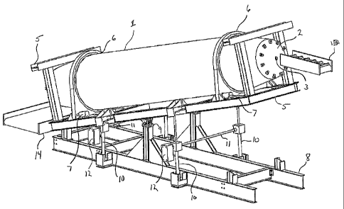
[000041] Figure 1 is a perspective view of an apparatus for processing solid
waste
products in accordance with one embodiment of the present invention.
[000042] Figure 1 a is another perspective view of an apparatus shown in
Figure 1.
11
CA 02606142 2007-10-25
WO 2006/121697 PCT/US2006/016773
[000043] Figure 2 is a cross section view of the vessel for processing solid
waste
products in accordance with one embodiment of the present invention.
[000044] Figure 3 is another perspective view of an apparatus for processing
solid
waste products in accordance with one embodiment of the present invention.
[000045] Figure 4 is a plan view of an apparatus for processing solid waste
products
in accordance with one embodiment of the present invention.
[000046] Figure 5 is a cross section view of the vessel for processing solid
waste
products in accordance with one embodiment of the present invention.
[000047] Figure 6 is a schematic of a waste processing system with which the
present invention may be used, for processing solid waste products in
accordance
with one embodiment of the present invention.
[000048] Figure 7 is a schematic of a waste processing system with which the
present invention may be used, for processing solid waste products in
accordance
with another embodiment of the present invention.
[000049] Figure 8 is a longitudinal view of the cylindrical portion of a
treatment
vessel, and shows an alternative embodiment of the present invention wherein a
plurality of straight blades are used in the vessel.
[000050] Figure 9 is an elevation view of the cylindrical portion of a
treatment
vessel, and shows an alternative embodiment of the present invention wherein a
plurality of straight blades are used in the vessel.
[000051] Figure 10 is a perspective view of the cylindrical portion of a
treatment
vessel, and shows an alternative embodiment of the present invention wherein a
plurality of straight blades are used in the vessel.
Detailed Description of the Preferred Embodiment
12
CA 02606142 2007-10-25
WO 2006/121697 PCT/US2006/016773
[000052] In accordance with the foregoing summary, the following provides a
detailed description of the preferred embodiment, which is presently
considered to
be the best mode thereof.
[000053] The invention relates to a process for recycling waste. This process
is
sterilizing high density materials such as glass, plastics, metals and
recovering
others from municipal solid waste (MSW) and converting paper, cardboard, food
waste, etc. to a usable fiber and separating it from other recyclable
materials.
[000054] Figure 1 shows an example of an apparatus for processing solid waste
products in accordance with one embodiment of the present invention.
[000055] Figure 1 shows a rotatably mounted cylindrical vessel 1 having a
first end,
a second end and an interior surface, at least one end terminating in a hatch
2 that
may be opened to allow access to the interior of the vessel and sealably
closed to
allow pressurization of the vessel. It is preferred that the vessel have a
hatch on
either end such that the vessel may be opened to allow access to the interior
of the
vessel and sealably closed to allow pressurization of the vessel the charge of
waste
products, and so that it may be loaded one end and removed at the other end.
This
may be done by using a ram that may push the treated charge from the vessel by
extending through the vessel.
[000056] Also shown in Figure 1 is a steam inlet 3 for injecting stem disposed
at
least one of the ends, and preferably at both ends. Steam inlet 3 may be
connected
to steam conduits (not shown) so as to introduce and maintain steam pressure
into
the vessel.
Figure 1 also shows a plurality of substantially straight blades 4 protruding
from the
interior surface of the vessel, and each blade extending substantially the
entire
13
CA 02606142 2007-10-25
WO 2006/121697 PCT/US2006/016773
length of the vessel, so as to be capable of transporting waste material from
the
bottom of the vessel toward the top of the vessel, and releasing the waste
material to
fall to the bottom of the vessel.
[000057] The vessel may be rotated with respect to upper frame portion 5, such
as
by virtue of mechanical sleeve drives 6. The apparatus also includes at least
one
motor or other means for rotating the vessel.
[000058] The motor(s) 7 may otherwise be connected to the vessel through
appropriate drive/transmission means, such as to sprocket by a chain or belt.
[000059] Typically, the motor and drive means will be mounted in such an
arrangement so as to move along with the movement of the vessel itself, such
as by
being mounted on a moveable frame 5 supporting the vessel.
[000060] Upper frame portion 5 in turn is supported by lower frame portion 8
that
includes fulcrum pivot portion 9. Also shown in Figure 1 are the mechanical
screw
actuators 10 on either side of fulcrum pivot portion 9 that move the vessel I
between
a position wherein the first end is higher than the second end and a position
wherein
the second end is higher than the first end. This movement allows the operator
to
balance the load of the charge of waste products both before and during the
steam
treatment. Balancing the charge of waste products during the steam treatment
permits the operator to render more uniform the heat transfer to the mass,
such as
by removing cold spots that may develop in the waste charge mass. The
actuators
may be linked in tandem across frame 8 by drive rods 11 that are driven be
respective electric motors 12.
[000061] The actuators 10 may include load sensors to determine the state of
balance of the charge of waste products as originally loaded. Should the
charge of
14
CA 02606142 2007-10-25
WO 2006/121697 PCT/US2006/016773
waste products be determined to be out of balance upon initial loading, the
actuators
may be used to redistribute the load to even its balance, either through back-
and-
forth oscillation or through rapid agitation, to cause the charge of waste
products to
shift in position within the vessel. The load sensors may provide signals or
information to a microprocessor or PLC controller that is provided with
programming
'instructions to access the load at each sensor, and to, provide feedback
instructions
to the actuators.
J0000621 Figure 1 also shows rotatably mounted cylindrical vessel 1 with the
first
end raised with respect to the second end, such as would be the position for
loading
the vessel with the aid of input conveyor 13. This position may also be used
to
discharge the waste products after treatment onto discharge conveyor 14, or to
urge
the charge of waste products toward the second end in order to level the load
of
waste products during processing. The position of vessel 1 may of course be
varied
along the range of positions from horizontal to any angle between the maximum
tilt
angle shown in Figure 1, and its corresponding opposite.
[000063] Figure 1a is another perspective view of an apparatus shown in Figure
1,
showing the discharge or second end lower than the input or first end.
[000064] Figure 3 shows, using the same reference numbers shown in Figure 1, a
rotatably mounted cylindrical vessel 1 as depicted in Figure 1 with the first
end and
the second end at about the same height such that the vessel is horizontal.
This
position is typical of those at which the vessel would be maintained during
operation,
with relatively small adjustments being made to urge the charge of waste
products
toward either end in order to level the load of waste products. This view also
shows
CA 02606142 2007-10-25
WO 2006/121697 PCT/US2006/016773
the second hatch 2a (having steam inlet 3a) which is used as an exit hatch for
the
treated waste product charge.
[000065] Conversely, Figure 4 shows a top plan view of the rotatably mounted
cylindrical vessel I as depicted in Figure 1 with the second end raised with
respect
to the first end, such as may be necessary to move the charge of waste
products
toward the first end in order to level the load of waste products.
[000066] Figure 5 is a longitudinal cross section view of the vessel system
for
processing solid waste products in accordance with one.embodiment of the
present
invention, using the same lead lines from the Figures 1 and 2 and taken along
line 5
- 5 of Figure 4. Figure 5 shows the angling of one of the blades such as 16a -
16d)
shown in Figure 2 (a cross-section along line 2 -2 of Figure 4), and also
shows that
neighboring pairs of blades converge alternately toward opposite ends of the
vessel.
This view also shows that the vessel may additionally comprise frusto-conical
sections at either end to assist in loading and unloading the vessel, and to
help
maintain portions of the charge of waste products oriented in the portion of
the
vessel provided with the blades for agitation. Figures 2 and 5 also show that
the
blades are preferably slightly twisted such that ends of adjacent blades that
converge are twisted away from one another while ends of adjacent blades that
diverge are twisted toward from one another.
[000067] Figures 8, 9 and 10 show views of the cylindrical portion of a
treatment
vessel as described herein, and shows an alternative embodiment of the present
invention wherein a plurality of straight blades are used in the vessel.
[000068] Figure 8 shows a longitudinal view of the cylindrical portion of a
treatment
vessel 20 in place of vessel I as described herein, wherein a plurality of
straight
16
CA 02606142 2007-10-25
WO 2006/121697 PCT/US2006/016773
blades 21 is used in the vessel. The blades 21 are mounted on individual
mounting
brackets 22 that serve to hold the blades 21 away from interior surface 23.
Figure 8
is a view taken from line 8 -8 of Figure 9. The mounting brackets 22 may also
be
used to mount the twisted blades as described herein.
[000069] Figure 9 is an elevation view of the cylindrical portion of a
treatment vessel
20, and shows in phantom a plurality of straight blades 21 and mounting
brackets 22
holding the blades 21 away from interior surface 23.
[000070] Figure 10 is a perspective view of the cylindrical.portion of a
treatment
vessel 20, and shows in phantom a plurality of straight blades 21 and mounting
brackets 22 holding the blades 21 away from interior surface 23.
[000071] Figure 6 is a schematic of a waste processing system with which the
present invention may be used, for processing solid waste products in
accordance
with one embodiment of the present invention that permits one-way steam flow
through the vessel. This figure shows the various components of a system
designed
to provide the vessel with steam, and the ancillary components of the
preferred
embodiment. This figure also shows the positions of valves and gauges using
standard indicia, such as control valves, check valves, thermocouples,
strainers,
pressure gauges, motors and pumps.
[000072] Figure 7 is a schematic of a waste processing system with which the
present invention may be used, for processing solid waste products in
accordance
with another embodiment of the present invention that permits two-way steam
flow
through the vessel that may be provided in pulses. This figure also shows the
positions of valves and gauges using standard indicia, such as control valves,
check
valves, thermocouples, strainers, pressure gauges, motors and pumps. This
17
CA 02606142 2007-10-25
WO 2006/121697 PCT/US2006/016773
schematic provides an example of .a system that permits steam, particularly
superheated steam, to be provided in pulses to the vessel of the present
invention.
[000073] The views of Figures 3 and 4 are used for illustrative purposes only,
and it
will be understood that the vessel may be titled to lesser degrees during
processing
in order to make lesser adjustments in the load distribution through leveling,
and that
such movement may be relatively rapid or slower and/or repetitive, depending
upon
the load situation presented.
[000074] Figure 2 also shows an example of a line 17 representing the top of a
waste product charge as it would appear once leveled within the vessel 1. The
waste product charge leaves a zone of space 18 above it such that a steam
region
extends the length of the vessel through which successive portions of the
waste
products will pass as the vessel rotates. It is preferred that the interior.
of the vessel
be substantially free of structure presenting surfaces that are not
substantially
parallel to the central longitudinal axis of the vessel.
[000075] The operation of the vessel can be appreciated from the cross-section
of
the apparatus shown in Figure 3, Figure 2 showing vessel 1, interior surface
15 and
blades 16a - 16d.
1000076] The blades may be straight and substantially parallel to the
longitudinal
axis of the vessel, or, as shown in Figure 2, preferably may be angled such
that
neighboring blade pairs (e.g., 16a and 16b) converge toward one end of the
vessel,
while successive blade pairs (e.g., 16b and 16c) converge toward the opposite
end
of the vessel, as seen in Figure 2. The straight blades permit portions of the
waste
charge to be raised vertically and dropped vertically as the vessel rotates.
The
angled blades as described above further cause an alternating side-to-side
18
CA 02606142 2007-10-25
WO 2006/121697 PCT/US2006/016773
movement of successive portions of the waste charge, as the vessel rotates, by
allowing successive portions of the waste charge to fall at an angle to the
vertical
such that the successive portions are moved gently from side to side without
compaction.
[000077] After the vessel is loaded with the charge of waste products, the
door
through which the charge was loaded is shut, steam is introduced continually
into the
vessel, and the vessel becomes pressurized. Fresh steam may be continuously
fed
into the vessel from the loading end, and after a predetermined processing
pressure
is reached, steam may be allowed to escape the vessel into the discharge steam
line.
[000078] The temperature and pressure of the vessel are monitored, and the
flow of
steam is regulated to keep the process within predetermined processing ranges
(typically around 50 psi, at 300 degrees F). The vessel is rotated at a
predetermined
speed (depending on the size of the vessel), and after a predetermined amount
of
time (typically 20 to 45 minutes), the pressure is released and the processed
waste
is removed.
[000079] The temperature of the charge of waste products may be monitored by
thermometers or thermocouples disposed along the length of the vessel. The
temperature readings are taken and applied to determine the temperature of
portions
of the charge of waste products. The thermometers or thermocouples may provide
signals or information to a microprocessor or PLC controller that is provided
with
programming instructions to access the temperature at each thermometers or
thermocouples, and to provide feedback instructions to the actuators. This
information may be used as feedback control to the actuators 9 in order to
adjust the
99
CA 02606142 2007-10-25
WO 2006/121697 PCT/US2006/016773
charge of waste products within the vessel so as to increase heat transfer to
portions
of the charge not receiving effective heat treatment, in order to maintain
overall
efficient heat transfer to the charge of waste products overall.
[0000801 A given charge of waste products may contain a wide variety of
constituents, such as wood, paper, organic matter, water, etc. Each charge of
waste
products presents its own heat capacity and transfer profile, while there is
required
an overall heat absorption of the mass in order to provide an effective
treatment of
the waste products charge.
[000081] The information from the thermometers or thermocouples may also be
used to determine the heat absorption over time as the charge of waste
products
heats up initially. This allows the operator (or a microprocessor or PLC
controller) to
extrapolate the energy needs for that charge of waste products and, based upon
a
comparison of the heat transfer profile, to also determine the approximate
qualitative
constituent make-up of the charge of waste products, and thus allow the
determination of the treatment time necessary to treat that particular charge.
[000082] In operating the vessel of the present invention, the vessel may be
tilted so
as to present the input hatch 2 upward with respect to the horizontal, and to
allow a
charge of waste products to be placed into the vessel with the aid of conveyor
13.
The hatch 2 is then closed and the waste products 17 charge (see Figure 2) may
optionally be leveled by a reciprocating action of the actuators 10 prior to
introduction
of steam, or upon initial introduction of steam.
[000083] Once the hatch 2 is sealed, steam is placed into the vessel through
inlets
3 and/or 3a to provide a pressurized steam environment in the vessel 1.
Examples
of systems used to produce and inject the steam are shown in Figures 6 and 7.
CA 02606142 2007-10-25
WO 2006/121697 PCT/US2006/016773
[000084] The vessel 1 is then rotated and the blades 16a - 16d (or blades 21
in
Figures 8 - 10) act to raise portions of the waste products charge 17 from the
bottom
to the top of the vessel, and then release them to fall through the a zone of
the
steam environment 18 of relatively low density (i.e., that space not occupied
by the
waste products 17 as seen in Figure 2. This zone increases in volume as the
waste
products 17 shrinks during the processing.
[000085] The cylindrically shaped vessel 1 has a number of blades to function
as a
stirring apparatus to homogenize heat and circulate the waste vertically
and/or
horizontally, and at least one opening to load and discharge waste (i.e.,
hatches 2
and 2a, respectively). The conical structures at the openings enhance the
input of
the waste products charge and the discharge of the treated waste. These
structures
also serve to maintain the waste in the central horizontal region of the
vessel. The
vessel may be titled by its longitudinal axis with respect to the horizontal
position for
effective waste loading into the vessel by the gravity force. This tilting may
also be
used during the processing to level the waste products charge.
[000086] According to the invention, steam inlets are connected to one or more
saturated or superheated steam supply and to a steam receiver. In this way,
the
vessel is pressurized and depressurized from one or more openings. Each
opening
may be provided with a pressure lock and bidirectional steam flow conduits and
valves. The apparatus may also include an optional steam vacuum pump at each
opening for rapid depressurizing of the vessel. Rotating union valves may also
be
included to enable steam flow in- out of the vessel as the vessel is rotating
or tilting.
These features are shown schematically in Figures 6 and 7.
21
CA 02606142 2007-10-25
WO 2006/121697 PCT/US2006/016773
(000087] Load cells that are attached to or independent of the actuator(s) and
connected to the frame structure detect when the process material within the
vessel
is non-uniformly distributed along the vessel's horizontal axis. Uniform
distribution of
waste in the vessel is attained by rotating the vessel on its latitude axis in
accordance with and by the reference to load cell signals.
[000088] As the vessel rotates, the temperature is monitored to determine the
change in temperature of the waste products charge over time. A plurality of
temperature sensors may be used to send feedback to the control to achieve
homogenous temperature in the vessel. The feedback control system and
controller
may include PLC or microprocessors that accept data from the temperature and
load
sensors and provide feedback control to the vessel rotation and the actuators
to
reposition and redistribute the waste charge load as required for efficient
processing.
[000089] It is preferred that the heated and pressurized vessel is rotated
bidirectionally, and at a constant or variable speed depending on the waste
type, to
attain homogenous heat transfer during the treatment cycle. As the waste
shrinks
due to the pressure and temperature, the volume of the waste charge decreases.
The open space, such as the volume of space 18, increases by shrinkage in the
vessel and serves as a hot region to provide heat treatment to portions of the
waste
charge that are raised and allowed to fall through this relatively low density
region.
This provides most complete and efficient exposure of the waste to the steam
environment.
[000090] This temperature data may also be used to determine the overall
absorption of energy over time which in turn allows the operator to
characterize the
waste products qualitatively (e.g., in terms of overall makeup of organic
matter,
22
CA 02606142 2007-10-25
WO 2006/121697 PCT/US2006/016773
paper, etc.) through pre-determined data on waste product constituents, and
thereby
to extrapolate the amount of time a given charge of waste products will
require to
complete processing. This information may be stored and fed back into the
control
system to determine a time when the processing may be stopped automatically or
through a signal to the operator.
[000091] As a result of steam condensation during this process, sludge may
develop, and to avoid mixing the recycled waste with the sludge, one or more
gaps
or perforations may be provided in the blades (preferably near the interface
between
the blades 16a - 16d and the interior surface 15; see e.g. blades 16b and 16d
having perforations and gaps, respectively) to allow the sludge to remain at
the
bottom of the vessel and the stirring mechanism and the chamber keeps the
sludge
at the bottom of the vessel. This may also be done by using the mounting
arrangement shown in Figures 8 --10. The perforations shown in Figure 2 may
also
be used in the straight blades shown in Figures 8 --10, and the mounting
arrangement shown in Figures 8 - 10 may also be used with the blade type and
arrangement shown in Figure 2.
[000092] Due to the fact that the amount of sludge would vary depending on the
steam type and quality, superheated, dry steam, may be used in place of
conventional saturated steam to reduce the amount of sludge.
[000093] Also, during rotation of the vessel, the thermocouples determine
whether
the waste products charge has developed relatively cold regions, such as
through
the make up of the charge itself, or through compaction, that is retarding the
rate of
heat transfer to that region. If a relatively cold region is detected, the
vessel may be
tilted and/or oscillated by the actuators to redistribute the mass along the
length of
23
CA 02606142 2007-10-25
WO 2006/121697 PCT/US2006/016773
the vessel. Also, in the event the waste products charge otherwise becomes
unbalanced, the actuators may tilt and/or oscillate the vessel to redistribute
the mass
along the length of the vessel. This may be done through PLC controllers or
microprocessors operating in conjunction with the thermocouples and actuators.
[000094] Through the action of the actuators, the waste charge can be
maintained
relatively evenly distributed along the length of the vessel during
processing, so that
the blades are able to raise portions of the waste products charge that are
substantially uniformly distributed along the length of the vessel, and to
allow those
portions to descend through a relatively low density zone created and
maintained
along the length of the treatment volume of the vessel.
[000095] The tilting pivot point is preferably located at the center of
gravity to
balance the weight at horizontal position and to incline the vessel at an
adjustable
bidirectional angle relative to its horizontal position. Mechanical linear
actuators,
chain systems, hydraulic actuators, pinion rack systems, and scissors systems,
etc.
are types of mechanisms that may be used in providing the tilting movement.
[000096] This system therefore prevents and dynamically rectifies unbalanced
loads
and any other sources of localized compaction of the waste products charge,
and
allows efficient treatment of the waste products charge by creating and
maintaining a
low density zone through which individual portions of the waste products
charge are
passed with increased efficiency and without compaction of portions of the
waste
products charge as occurs in other treatment vessel systems with active
transport
systems or vessels that permit portions of the waste products charge to remain
compressed or in a state of non-uniform distribution.
24
CA 02606142 2007-10-25
WO 2006/121697 PCT/US2006/016773
[000097] It is apparent that while specific embodiments of the invention is
disclosed,
various modifications of the apparatus or parameters of the process may be
made
which will be within the spirit and scope of the invention. Therefore the
spirit and
scope of the present invention should be determined by reference to the claims
below.