Note: Descriptions are shown in the official language in which they were submitted.
CA 02606469 2007-10-29
WO 2006/117640 PCT/IB2006/001085
-1-
APPARATUS AND METHOD FOR ADMINISTERING OPHTHALMIC SOLUTIONS
Field of the Invention
The present invention concerns a dispensing apparatus for liquid products,
particularly medicinal products, such as an ophthalmic solution. This design
allows no ullage
to be left in the apparatus during ejection of the liquid, and thus will not
result in quality loss of
residual solution within the apparatus between dosing sessions. This is
particularly important
for medicinal products, and particularly ophthalmic solutions. Also, dosing is
more accurate,
and the patient is less likely to overdose and experience ocular irritation.
Background of the Invention
Although the principles of the present invention may have utility in many
areas, for
convenience it will be described mainly in connection with a liquid treatment
for eyes.
Weinreb RN and Khaw PT, Lancet, 2004; 363: 1711-1720 discuss various eye
conditions,
such as primary open-angle glaucoma, and is incorporated herein by reference.
Typically the
medical preparation must be delivered in a fairly well defined volume to
assure a specified
dose is delivered or absorbed. A large surplus cannot be allowed due to
improper systemic
physiological effects from absorbency in non-target tissue or drainage of
excess amounts
through the tear channel into the throat cavity, or the inconveniences caused
by overflow on
face and clothes. Also price considerations apply to expensive medications. As
an example,
the treatment of glaucoma requires frequent daily administrations of e.g.
prostagiandins, beta-
blockers or other expensive active ingredients, all having other than the
desired pressure
relieving action when absorbed by other body tissues than the eye. Small
volume dosing is
negatively affected by even small uncontrolled or dead spaces in delivery
equipments used.
Moreover, medical preparation components may be sensitive to degradation or
absorption at
prolonged exposure to materials and extended surfaces present in delivery
devices. Similar
considerations apply for sterility preservation. With regard to stream
quality, proper
administration of small amounts is complicated by the fact that the active
ingredients cannot
enter the eye but through the limited area of the cornea. It is also necessary
that the entire
dose be delivered before the triggered blink reflex closes the eyelid.
A large number of devices are already known for applying a specified quantity
of a
liquid medicinal product onto a part of the body, such as an ophthalmic
solution, on the
surface of the eye. These devices generally rely on the principle of a syringe
which can be
either pre-filled with a specified quantity of liquid, or graduated to suck up
said quantity of
liquid contained in a separate bottle, or connected to a fixed receptacle in
permanent
communication with the dosing chamber of the syringe, as is described for
example in one of
the embodiments of US Patent No. 4,623,337. It will be observed that
permanently feeding
the dosing chamber from the receptacle via gravity means that neither the
precision of the
quantity of liquid to be ejected, nor the sterility thereof, can be
guaranteed. In these devices,
CA 02606469 2007-10-29
WO 2006/117640 PCT/IB2006/001085
-2-
the pressure exerted on the plunger, manually or automatically, is generally
exerted in the
same direction as that of the liquid jet, as is described for example in
Patent Cooperation
Treaty Publication WO 92/20455.
The direction of the jet can sometimes be deviated by bent conduits, but it is
then
difficult to control the force with which the jet reaches its target. A device
of this kind similar
to, for example, that disclosed in French Patent No. FR 2 647 757 for food
products or
cosmetics in liquid or paste-like form, for which respecting a given ejection
pressure is of no
importance.
In the case of a an ophthalmic solution, it is, however, very important not
only to
control very precisely the dose to be ejected for obvious reasons of safety
and efficacy of the
treatment, but also in order to be able to control the impact pressure of the
liquid jet on the
eye, which certain devices attempt to achieve by using an eyepiece or a
spacing member
applied to find the periphery of the target to impose a fixed distance with
respect to the liquid
ejection orifice, as is disclosed for example in US Patent Nos. 4,623,337 and
5,836,911. It
will be observed however that these devices do not always allow the impact
force of the liquid
jet to be reproduced when the pressure is exerted directly on the plunger
manually.
The present design allows no ullage to be left after a precise quantity of
liquid has
been ejected, eliminating an important risk associated with traditional
technology: quality loss
of residual solution in the apparatus between dosing sessions. Both the
ejection of a precise
quantity of liquid and maintenance of solution quality are particularly
important for medicinal
products, and particularly ophthalmic solutions. This design also provides
accurate horizontal
delivery of liquid to a target surface (like an eye) with minimal effort and
with minimal
dependence on a patient's dexterity. The design minimizes dosing failures
associated with
traditional technology, ensuring that only 1 dosing session is required. The
design ensures
more efficient use by the patient, and reduces the medical safety risks
associated with
multiple attempts to dose medication (like overexposure to active drug,
increased ocular
irritation due to increase volume of irritants in the formulation, higher risk
of infection due to
increased frequency of eye contact).
The design also allows for horizontal delivery of liquid to facilitate those
who have
difficulties angling their head, which is required for successfully
administrating eye drops
using traditional technology.
Thus, the dispensing apparatuses of the prior art provide individual solutions
to
particular problems, but none of them allows all of the aforementioned
problems to be
simultaneously resolved.
Summary of the Invention
The invention relates to an apparatus for dispensing a liquid product
comprising:
a) housing or frame having an opening, b) a receptacle for the liquid with a
feed
nozzle arranged substantially stationary with respect to the housing or frame,
c) a dosing
chamber having a valve containing at least a first orifice and a second
orifice, d) a mechanism
CA 02606469 2007-10-29
WO 2006/117640 PCT/IB2006/001085
-3-
arranged to allow ejection of liquid through the second orifice, and e) a
through passage
arranged to allow the ejected liquid to pass in a direction different from the
feed nozzle and
out of the opening, wherein i) the mechanism comprises a mobile element
movable with
respect to the housing or frame between at least a first position in which the
first orifice of the
dosing chamber and the feed nozzle are in flow communication and a second
position in
which the second orifice and the through passage are in flow communication,
and ii) the
mechanism is arranged to allow aspiration of liquid through the first orifice
when the mobile
element is in the first position and ejection of liquid through the second
orifice when the
mobile element is in the second position.
An embodiment of the invention relates to the apparatus, wherein the housing
optionally comprises an eyepiece.
Another embodiment of the invention relates to the apparatus, wherein the
eyepiece
optionally comprises an eyepiece ring.
Another embodiment of the invention relates to the apparatus, wherein the
eyepiece
ring is comprised of thermoplastic elastomer or silicone.
In yet another embodiment, the invention relates to the apparatus, wherein at
least
one actuator is included and is adapted to operate the mechanism.
An embodiment of the invention relates to the apparatus, wherein the actuator
is
arranged to be maneuvered by application of manual force.
Another embodiment of the invention relates to the apparatus, wherein the
actuator is
adapted to move or carry the mobile element between a filling position, when
the mobile
element is in the first position, and an ejection position, when the mobile
element is in the
second position.
In yet another embodiment, the invention relates to the apparatus, wherein the
actuator is adapted to perform a substantially continuous movement during
which the
mechanism performs at least the aspiration step and the movement of the mobile
element
between the first position and the second position.
In yet another embodiment, the invention relates to the apparatus, wherein the
actuator mobilizes the mobile element in substantially continuous movement
between the first
position and the second position.
An embodiment of the invention relates to the apparatus, wherein the actuator
mobilizes the mobile element in substantially continuous movement to fill the
dosing chamber
with the liquid product at the first position.
An embodiment of the invention relates to the apparatus, wherein the actuator
is
arranged to mobilize the mobile element in a substantially continuous movement
to eject the
liquid product from the dosing chamber at the second position.
Another embodiment of the invention relates to the apparatus, wherein the
actuator is
adapted to give a tactile feedback immediately before the ejection step in the
continuous
movement.
CA 02606469 2007-10-29
WO 2006/117640 PCT/IB2006/001085
-4-
Another embodiment of the invention relates to the apparatus, wherein the
mobile
element is adapted to move in a substantially vertical direction.
In yet another embodiment, the invention relates to the apparatus, wherein the
mobile
element is adapted to move or carry the dosing chamber in a substantially
horizontal
direction.
In yet another embodiment, the invention relates to the apparatus, wherein the
dosing
chamber comprises a substantially cylindrical barrel, defining a concentric
barrel axis.
An embodiment of the invention relates to the apparatus, wherein the first
orifice is
adapted to connect to the aspiration element.
Another embodiment of the invention relates to the apparatus, wherein the
mobile
element comprises an aperture, that when the mobile element is in first
position, the aperture
is adapted to be blocked, and when the mobile element is in the second
position, the aperture
is aligned with the second orifice and the opening to eject fluid.
In yet another embodiment, the invention relates to an apparatus, wherein the
mechanism is adapted to perform in sequence the aspiration of liquid in the
first position, the
movement of the mobile element to the second position, and the ejection of
liquid.in the
second position.
In yet another embodiment, the invention relates to the apparatus, wherein the
mechanism is adapted to perform the aspiration by retraction of a pump member
against a
return spring and to perform the ejection by protraction of a pump member by
return spring.
An embodiment of the invention relates to the apparatus, wherein the mechanism
is
adapted to return to the start or rest position also after liquid ejection.
Another embodiment of the invention relates to the apparatus, wherein the
mechanism is adapted to return to the start or rest position before liquid
ejection.
In yet another embodiment, the invention relates to the apparatus, wherein the
feed
nozzle is disposed at a proximal end of the receptacle.
In yet another embodiment, the invention relates to the apparatus, wherein the
dosing
chamber is in operative communication with the feed nozzle.
An embodiment of the invention relates to the apparatus, wherein the mobile
element
is linear cam face shaped.
An embodiment of the invention relates to the apparatus, wherein the mobile
element
has a cam surface.
Another embodiment of the invention relates to the apparatus, wherein the
dosing
chamber comprises an aspiration element therein.
Another embodiment of the invention relates to the apparatus, wherein the
aspiration
element has a cylindrical shape.
Another embodiment of the invention relates to the apparatus, wherein the
aspiration
element is a cannula.
CA 02606469 2007-10-29
WO 2006/117640 PCT/IB2006/001085
-5-
In yet another embodiment, the invention relates to the apparatus, wherein the
aspiration element is formed of a hard plastic material.
In yet another embodiment, the invention relates to the apparatus, wherein the
aspiration element is formed of polycarbonate (PC).
In yet another embodiment, the invention relates to the apparatus, wherein the
aspiration element is formed of metal.
An embodiment of the invention relates to the apparatus, wherein the
aspiration
element is formed of acrylonitrile butadiene styrene (ABS).
Another embodiment of the invention relates to the apparatus, wherein the
second
orifice is adapted to create a liquid spray.
In yet another embodiment, the invention relates to the apparatus, wherein the
second orifice is adapted to create a substantially coherent stream.
In yet another embodiment, the invention relates to the apparatus, wherein the
second orifice is adapted to eject liquid substantially directly into the air.
In yet another embodiment, the invention relates to the apparatus, wherein the
second orifice is adapted to create a steam of droplets.
In yet another embodiment, the invention relates to the apparatus, wherein the
stream of droplets is a horizontal stream.
The invention relates to a method of operating an apparatus for dispensing a
liquid
product, comprising:
a) housing or frame having an opening, b) a receptacle for the liquid with a
feed
nozzle arranged substantially stationary with respect to the housing or frame,
c) a dosing
chamber having a valve containing at least a first orifice and a second
orifice, d) a mechanism
arranged to allow ejection of liquid through the second orifice, and e) a
through passage
arranged to allow the ejected liquid to pass in a direction different from the
feed nozzle and
out of the opening, the method comprising i) connecting the first orifice and
the nozzle in flow
communication, ii) filling liquid into the dosing chamber through the first
orifice, and iii)
ejecting liquid from the dosing chamber through a second orifice onto an
ophthalmic target.
The invention relates to a kit for operating an apparatus for dispensing a
liquid
product, the kit comprising an apparatus for dispensing a liquid product, a
liquid product, and
directions for use; the apparatus comprising:
a) housing or frame having an opening, b) a receptacle for the liquid with a
feed nozzle
arranged substantially stationary with respect to the housing or frame, c) a
dosing chamber
having a valve containing at least a first orifice and a second orifice, d) a
mechanism
arranged to allow ejection of liquid through the second orifice, and e) a
through passage
arranged to allow the ejected liquid to pass in a direction different from the
feed nozzle and
out of the opening.
An embodiment of the invention relates to the kit, wherein the liquid product
is an
ophthalmic solution.
CA 02606469 2007-10-29
WO 2006/117640 PCT/IB2006/001085
-6-
An embodiment of the invention relates to the kit, wherein the ophthalmic
solution is a
composition comprising latanoprost or a pharmaceutically acceptable salt or
solvate thereof.
The invention relates to a method of treating an ophthalmic condition, the
method
comprising an apparatus for dispensing a liquid product, the apparatus
comprising:
a) housing or frame having an opening, b) a receptacle for the liquid with a
feed
nozzle arranged substantially stationary with respect to the housing or frame,
c) a dosing
chamber having a valve containing at least a first orifice and a second
orifice, d) a mechanism
arranged to allow ejection of liquid through the second orifice, and e) a
through passage
arranged to allow the ejected liquid to pass in a direction different from the
feed nozzle and
out of the opening, wherein the liquid product comprises a pharmaceutically
effective amount
of an ophthalmic solution.
Another embodiment of the invention relates to the method, wherein the
ophthalmic
solution is a composition comprising latanoprost or a pharmaceutically
acceptable salt or
solvate thereof.
Another embodiment of the invention relates to the use of a pharmaceutically
effective amount of an ophthalmic solution for the treatment of an ophthalmic
condition
wherein the ophthalmic solution is provided to the patient via an apparatus
comprising: a) a
housing or frame having an opening, b) a receptacle for the ophthalmic
solution with a feed
nozzle arranged substantially stationary with respect to the housing or frame,
c) a dosing
chamber having a valve containing at least a first orifice and a second
orifice, d) a mechanism,
arranged to allow ejection of the ophthalmic solution through the second
orifice, and e) a
through passage arranged to allow the ejected ophthalmic solution to pass in a
direction
different from the feed nozzle and out of the opening.
In yet another embodiment of the invention relates to the use wherein the
ophthalmic
solution contains an active ingredient latanoprost.
In still yet another embodiment, the invention relates to the use wherein the
ophthalmic solution contains a combination of active ingredients latanoprost
and timolol
maleate.
An embodiment of the invention relates to a kit for use in the treatment of
ophthalmic
conditions, the kit comprising an ophthalmic solution, an apparatus for
administering the
ophthalmic solution and directions for use; the apparatus comprising: a) a
housing or frame
having an opening, b) a receptacle for the ophthalmic solution with a feed
nozzle arranged
substantially stationary with respect to the housing or frame, c) a dosing
chamber having a
valve containing at least a first orifice and a second orifice, d) a mechanism
arranged to allow
ejection of the ophthalmic solution through the second orifice, and e) a
through passage
arranged to allow the ejected ophthalmic solution to pass in a direction
different from the feed
nozzle and out of the opening.
An yet another embodiment, the invention relates to a kit wherein the
ophthalmic
solution contains latanoprost.
CA 02606469 2007-10-29
WO 2006/117640 PCT/IB2006/001085
-7-
In another embodiment, the invention relates to a kit wherein the ophthalmic
solution
contains latanoprost and timolol maleate.
An embodiment of the invention relates to an ophthalmic composition
comprising: a
pharmaceutically effective amount of latanoprost solution and an apparatus for
holding the
latanoprost solution, the apparatus comprising: a) a housing or frame having
an opening, b) a
receptacle for the latanoprost solution with a feed nozzle arranged
substantially stationary
with respect to the housing or frame, c) a dosing chamber having a valve
containing at least a
first orifice and a second orifice, d) a mechanism arranged to allow ejection
of the latanoprost
solution through the second orifice, and e) a through passage arranged to
allow the ejected
latanoprost solution to pass in a direction different from the feed nozzle and
out of the
opening.
An embodiment of the invention relates to a use of a composition for providing
an
ophthalmic solution wherein said composition comprises: a pharmaceutically
effective amount
of a ophthalmic solution and an apparatus for holding the ophthalmic solution,
the apparatus
comprising: a) a housing or frame having an opening, b) a receptacle for the
ophthalmic
solution with a feed nozzle arranged substantially stationary with respect to
the housing or
frame, c) a dosing chamber having a valve containing at least a first orifice
and a second
orifice, d) a mechanism arranged to allow ejection of the ophthalmic solution
through the
second orifice, and e) a through passage arranged to allow the ejected
ophthalmic solution to
pass in a direction different from the feed nozzle and out of the opening.
In yet another embodiment, the invention relates to the use wherein the
ophthalmic
solution contains latanoprost.
In still another embodiment, the invention relates to the use wherein the
ophthalmic
solution contains latanoprost and timolol maleate.
Other features and advantages of the present invention will appear more
clearly upon
reading embodiment examples, given purely by way of non-limiting illustration,
with reference
to the annexed drawings, in which:
Figure 1 shows a perspective view of a dispensing apparatus according to the
invention with the housing attached.
Figure 2 shows a frontal perspective view of a dispensing apparatus according
to the
invention with the housing attached.
Figure 3 is an exploded perspective view of the apparatus shown in Figure 1.
Figure 4 shows a cross-section along the line V-V of Figure 1, of the
mechanism
assembly in the rest position.
Figure 5 shows an exploded perspective view of the eyepiece shown in Figure 1.
Figure 6 shows perspective views of the mobile element as shown in Figure 3.
Figure 7 shows perspective view of the mobile element in the ejection
position.
Figure 8 shows perspective view of the front face of dosing chamber.
CA 02606469 2007-10-29
WO 2006/117640 PCT/IB2006/001085
-8-
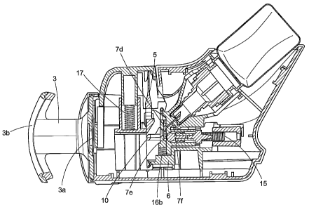
In Figure 1, a perspective view is shown of an embodiment depicting a
disposable
multi-dose dispensing apparatus according to the invention. Figure 1
externally depicts the
apparatus, which includes a housing formed of two shells, housing right 1 and
housing left 2,
assembled by any suitable means. The liquid product, which will be ejected
from the
apparatus through the air in the direction of the ophthalmic target, the
cornea of the eye for
example, is contained in a receptacle 18 which is substantially stationary
with respect to the
housing and support. The liquid product contained in the receptacle 18 comes
in fluid
communication with the dosing chamber 7, via aspiration, after the dosing
chamber 7 is
pressurized by the retraction of plunger sealing 11. Once the dosing chamber 7
has been
pressurized and is filled with liquid product, the plunger sealing 11 and
plunger 12 protract to
eject fluid onto the ophthalmic target.
In Figure 1, it can be seen that actuation by a vertical force is effected in
a
substantially perpendicular direction to the direction of the ejected liquid
product. The
actuation mechanism takes the form of an actuator 4. Reference will now be
made to Figure
3, in which housing right 1 and housing left 2 have been removed. The actuator
4 is
configured to receive mobile element 5 and actuator spring 17. The mobile
element 5 forms
the mobile component, which drives the plunger 12, attached to piston 10,
either toward or
away from the ophthalmic target. Mobile element 5 has a linear cam face shape
and is
operatively connected to actuator 4 at an elongated portion 5c and at arms 5b
and 5a. Mobile
element 5 also has a cam surface 5d, which operates to engage piston 10 to
cause plunger
12 to retract and protract. Mobile element 5 also includes at its center an
orifice 5e, Figure 6,
corresponding to a through passage, that when aligned with dosing orifice 7d,
liquid product
will be ejected through and onto the ophthalmic target. The particular
structure of actuator 4,
being in operative communication with mobile element 5 and actuator spring 17,
contributes
to the precision of the quantity of liquid ejected and to the non-
contamination of the dosing
chamber 7 by external polluting agents.
As shown in Figure 6, mobile element 5 is a linear cam face shaped component,
which forms the mobile element of the invention. At the rest phase, a user may
manually
exert an external vertical force onto the actuator 4. This force moves the
mobile element 5 in
a plane perpendicular to the ejection plane. Piston 10 extends horizontally
over the dosing
chamber 7 and the valve assembly 19. At a certain point in the movement of the
mobile
element 5 along the plane, the cam surface 5d is in operative communication
sliding along,
and pushing the exposed outer surface of the piston 10. This operative
communication
results in a retraction of the piston assembly 10a, simultaneously causing
plunger 12 to
retract.
When plunger sealing 11 retracts, pressure is then created and aspiration
occurs
causing liquid to flow from the receptacle 18 into the dosing chamber 7 by
valve seal 9. For
stability, the plunger sealing 11 acts to seal and guide the plunger 12, and
the combination of
the piston 10, plunger sealing 11, and plunger 12 combine to form piston
assembly 1 0a. The
CA 02606469 2007-10-29
WO 2006/117640 PCT/IB2006/001085
-9-
driving spring 15, housed in plunger spring guide 13, is situated behind the
piston 10 and is
provided to store potential energy resulting from the retraction of the piston
assembly 10a.
The cam surface 5d acts as the dosing mechanism causing retraction of the
plunger 12 at a
distance that is directly proportional to the angle of protrusion of the cam
surface 5d. Once
piston assembly 10a has retracted to a point directly proportional to the
greatest angle of
protrusion, position 5f, the mobile element 5 then continues moving along the
plane. At a
protrusion angle of about 0 , position 5g, the potential energy stored within
the driving spring
is released, causing the plunger 12 to protract, simultaneously ejecting fluid
from the
dosing chamber 7 through orifice 5e onto the ophthalmic target in the form of
a spray or
10 stream. The amount or dose of liquid product entering the dosing chamber 7
from receptacle
18 is defined by the tipping angle of mobile element 5. Once the liquid
product is ejected from
the apparatus, the external force exerted onto the actuator 4 by the user may
be removed,
and the actuator spring 17 acts to return the actuator 4 to its original
position.
The actuator spring 17 is housed in cylinder 6a of support 6, which abuts the
bottom
15 surface of actuator 4. Return valve springs 16 are disposed between valve 8
and valve spring
guide 14. When in the rest phase, no force is exerted onto the actuator 4.
When a user a
exerts manual vertical force onto actuator 4, actuator spring 17 and valve
spring- 16 then
become compressed. The vertical compression of actuator spring 17 and valve
spring 16
stores potential energy in this active phase, and upon release, expends this
energy and
restores the actuator 4 to the original rest phase.
As can be seen more clearly in enlarged Figure 6, mobile element 5 includes an
orifice 5e, for ejection of the liquid product onto the ophthalmic target. The
mobile element 5
is configured to have a cam surface 5d, which abuts a piston assembly 10 at a
certain point
when mobile element 5 moves in a plane perpendicular to the ejection plane.
Valve assembly
19 is comprised of a valve 8 and a valve seal 9 which abut front face dosing
chamber 7a.
Valve 8 and valve seal 9 work in concert to contain the pressure in the dosing
chamber 7.
As shown in Figure 3, the dosing chamber 7 is comprised of a substantially
cylindrical
barrel that defines a concentric barrel axis and having a substantially
constant cross-section
area perpendicular to the barrel axis, and having an aspiration element 7f and
a plunger 12
inserted in the barrel, the plunger 12 being movable along the barrel axis.
Additionally, orifice
5e has a substantially smaller cross-sectional area than the barrel.
Front face dosing chamber 7a includes two apertures, a dosing orifice 7d and
an
ejection orifice 7e. When in the active phase, at a first position 5d, the
mobile element 5 acts
to retract the plunger 12 in a direction opposite the ophthalmic target to
fill the dosing
chamber 7. The pressure created in the dosing chamber 7 fills dosing orifice
7d. The mobile
element 5 then continues moving along the plane, and at a second position 5g,
the liquid
product in the dosing orifice 7d moves to the ejection orifice 7e and the
liquid product is
ejected through the eyepiece orifice 3b onto the ophthalmic target through
orifice 5e. The
CA 02606469 2007-10-29
WO 2006/117640 PCT/IB2006/001085
-10-
ejection orifice 7e is substantially narrower than eyepiece orifice 3b or
orifice 5e and, the
eyepiece orifice 3b is substantially wider than the orifice 5e and the
ejection orifice 7e.
Housing right 1 and housing left 2 are each formed of hard plastic material,
such as
bisphenol A, also known as polycarbonate (PC) Lexan manufactured by General
Electric
company or acrylonitrile butadiene styrene (ABS), both plastics are
commercially available
from Modern Plastics located in Bridgeport, Connecticut, USA, or any suitable
hard plastic
material available to one of ordinary skill in the art.
The actuator 4 is formed of hard plastic material, such as polycarbonate (PC)
Lexan
or acrylonitrile butadiene styrene (ABS), or any suitable hard plastic
material commercially
available to one of ordinary skill in the art.
The mobile element 5 is formed of hard plastic material, such as such as
polycarbonate (PC) Lexan or acrylonitrile butadiene styrene (ABS), or any
suitable hard
plastic material commercially available to one of skill in the art.
Dosing chamber 7 is formed of hard plastic material, such as polycarbonate
(PC)
Lexan or acrylonitrile butadiene styrene (ABS), or any suitable hard plastic
material
commercially available to one of ordinary skill in the art.
The receptacle 18 interfaces with the dosing chamber 7 at feed nozzle 18a.
This
interface may be achieved by a lock and groove mechanism. Receptacle 18 is
formed of a
plastic material, such as high-density polyethylene (HDPE) commercially
available from
Equistar, located in Houston, Texas, USA, or polypropylene (PP), or any
suitable hard plastic
material commercially available to one of ordinary skill in the art.
The aspiration element 7f has substantially cylindrical shaped, such as that
of a
spike, and is formed of a metal, such as steel, or hard plastic material such
as polycarbonate
(PC) Lexan or acrylonitrile butadiene styrene (ABS), (PE), (HDPE), or any
suitable hard
plastic material commercially available to one of ordinary skill in the art.
The aspiration
element 7f may also have a securing means, such as a barb or knob, to help
secure to the
receptacle 18.
Piston 10, is affixed to support 6 and chamber 7 of the apparatus and is
formed of a
hard plastic material, such as Celanex polybutylene terephthalate copolymer
(PBT)
commercially available from Ticona North America located in Florence,
Kentucky, USA, or
any suitable hard plastic material commercially available to one of ordinary
skill in the art.
Plunger 12 is formed of a hard plastic material, such as high-density
polyethylene
(HDPE), linear low-density polyethylene (LLDPE), or polypropylene (PP), or any
suitable hard
plastic material commercially available to one of ordinary skill in the art.
Optionally, the
plunger may be formed of the same material as the receptacle 18.The plunger 12
constitutes
an embodiment of the invention allowing the objectives of precision and
sterility to be
achieved for the dispensing apparatus, but other types of plunger may be used
without
departing from the scope of the invention.
CA 02606469 2007-10-29
WO 2006/117640 PCT/IB2006/001085
-11-
Plunger sealing 11 is formed of a flexible plastic material, such as Huntsman
polyethylene or Huntsman polypropylene (PP) commercially available from
Huntsman The
Woodlands Texas, USA, or any suitable flexible plastic material commercially
available to one
of ordinary skill in the art.
The valve 8 is formed of a hard plastic material, such as Celanex
polybutylene
terephthalate copolymer (PBT), or any suitable hard plastic material
commercially available to
one of ordinary skill in the art.
The valve seal 9 is formed of a soft elastomeric, such as DanFlex
commercially
available from to one of ordinary skill in the art or Santoprene TPE
commercially available
from Advanced Elastomer Systems located in Akron, Ohio, USA, or any suitable
soft
thermoplastic elastomer commercially available to one of ordinary skill in the
art.
The plunger spring guide 13 and valve spring guide 14 are both formed of a
harder
plastic material, such as (HDPE) or (PP), or any suitable hard plastic
material commercially
available to one of skill in the art.
The actuator spring 17, the valve spring 16, (valve spring right 16b and valve
spring
left 16a) and driver spring 15 are each formed of steel, such as stainless
steel, commercially
available to one of ordinary skill in the art.
Eyepiece assembly 3 is housed onto both housing right 1 and housing left 2.
Referring to Figure 1, Eyepiece assembly 3 is immobile, but may optionally be
mobile, for
example retractable for ease of storing the apparatus. Eyepiece assembly 3 is
provided to
guide the administration of ophthalmic liquid product into the eye. The outer
ring of eyepiece
3a is formed of a soft flexible material, such as Santoprene TPE, VersaFlex ,
or silicone
commercially available to one of skill in the art and is provided for comfort.
The eyepiece 3 is
formed of hard plastic material, such as polycarbonate (PC) Lexan or
acrylonitrile butadiene
styrene (ABS), or any suitable hard plastic material commercially available to
one of ordinary
skill in the art.
Support 6 is operatively connected to actuator 4, the mobile element 5, the
dosing
chamber 7, the piston assembly 10a, the valve assembly 19, and the valve
spring guide 14.
Support 6 is formed of a hard plastic material, such as Celanex polybutylene
terephthalate
copolymer (PBT), or any suitable hard plastic material commercially available
to one of skill in
the art. Support 6 is itself housed onto the interior of both housing right 1
and housing left 2
of the apparatus.
The liquid product envisioned by the invention concerns ophthalmic solutions,
such
as for example Xalatan and Xalacom , or any latanoprost containing solution,
timolil
compositions, dry eye solutions, topical eye solutions, topical antibiotics,
such as Visine , or
any product containing active ingredients such as tetrahydrozoline HCL or zinc
sulfate, or any
suitable ophthalmic solution known to one of ordinary skill in the art.
The apparatus may optionally be adapted to include a dose counter, a switch to
display the date and time, etc.
CA 02606469 2007-10-29
WO 2006/117640 PCT/IB2006/001085
-12-
A suitable kit would include the ophthalmic solution, for example Xalatan ,
the
apparatus, and directions for use.
All apparatus components work in concert to facilitate ophthalmic dosing, and
subsequent delivery. In addition, all apparatus components are formed of
medium-weight
cost effective components, which lend to the disposable nature of the device.
Filling position
From the filling position shown in Figure 4, by exerting a vertical force on
actuator 4,
the cam surface 5d causes piston assembly 10a to move in a direction opposite
the
ophthalmic target, thereby retracting plunger 12, subsequently compressing
valve spring 16.
In this position the receptacle 18 is in liquid communication with dosing
chamber 7, via the
aspiration element 7f, which enables the dosing chamber 7 to fill with liquid
product. By
exerting a vertical force on actuator 4, at position 5f, chamber 7 fills with
the fully dosed liquid
product.
Eiection position
By continuing to exert vertical pressure, on the actuator 4, mobile element 5
releases
piston assembly 10a as shown in Figure 7. Liquid product then fills ejection
orifice 7e, and
orifice 5e is aligned therewith. The liquid to be ejected is ejected through
both ejection orifice
7e and orifice 5e by virtue of the return action of the driving spring 15. By
releasing the
vertical external force on actuator 4, mobile element 5 pivots upward just
inside piston 10
sliding upward in the opposite the direction of the vertical force by return
action of button
spring 17 and valve spring 16.
It is clear that the devices described are arranged for multi-dose
applications, i.e.
applications in which doses are repeatedly drawn from a supply and repeatedly
ejected. It is
also clear that the devices are exemplified with features suitable for eye
treatment
applications. Typical parameters for this application will be given below
although the
invention shall not be regarded as limited to this application or any such
exemplified
parameter. A typical single dose volume for delivery to the eye can be less
than 100 pL,
suitably less than 50 pL, and suitably less than 30 pL. Generally the volume
in the standby
position is at least 1 pL, suitably at least 2 pL and suitably at least 3 pL.
The receptacle 18
suitably has the capacity to deliver a plurality of such doses.
A suitable distance from the outlet of the apparatus to the eye is about 24
mm. A
suitable jet time is from about 40 to about 60 ms. A suitable speed for the
stream of drops or
jet ejected is a balance between having enough linear momentum to traverse an
air gap
between apparatus opening and target, without gravity assistance, traveling
fast enough not
be obstructed by blinking, and not causing an inconvenient, harmful impact on
the eye. The
ideal speed is to some extent dependent on the drop size used but as a general
rule the
drops should be able to traverse at least 1 cm, suitably at least 3 cm and
most suitably at
least 5 cm through air by its own momentum, incorporating reasonable distances
between
opening and target. A suitable lower speed limit when leaving the apparatus
opening is 0.1,
CA 02606469 2007-10-29
WO 2006/117640 PCT/IB2006/001085
-13-
m/s, suitably 0.5 m/s, suitably at least 5 m/s and most suitably at least 10
m/s. Generally the
upper speed is lower than 200 m/s and suitably lower than 100 m/s. A suitable
drop size so
defined should be sufficient not to be retarded too quickly and not to be
easily redirected, e.g.
to be inhaled, and suitably has a minimum diameter of 20 pm, suitably not less
than 50 pm
and most suitably at least 100 pm. Normally the size is less than 200 pm and
suitably less
than 150 pm.
The stream may take the form of a horizontal shower or spray of atomized
liquid
droplets but suitably the stream is narrow and fairly coherent although even
such a stream
tends to break up into individual droplets after a certain time and distance.
The above given
values are intended to relate to spherical droplets and for multiple droplets
to the weight
average of particle diameters. A coherent stream tends to break up into
droplets of a
diameter of roughly double the diameter of the stream. Accordingly suitable
opening
diameters for the dosing orifice are about half the above given drop diameters
or roughly
between 10 and 1000 pm, suitably between 20 and 800 pm. The above
considerations are
fairly independent of liquid viscosity and tend to apply both for liquid
products and ointments.
It is desirable that the whole dose can be delivered in a time shorter than
the blink reflex time,
i.e. in a time shorter than about 150 m/s, suitably shorter than 100 m/s and
most suitably
shorter than 75 m/s.