Note: Descriptions are shown in the official language in which they were submitted.
CA 02606619 2014-06-10
78543-398
GAS HANDLING IN A WELL ENVIRONMENT
BACKGROUND
[0001] In many well environments, gases can build up and interfere
with the
production of desired liquids. Hydrocarbon based liquids, for example, can be
produced
by electric submersible pumping systems that are deployed within a wellbore.
These
types of pumping systems utilize centrifugal pumps having multiple stages that
rely on
impellers to move the produced liquid. However, the presence of sufficient gas
in the
liquid can lead to a buildup of gas on the suction surface of impeller blades,
causing
premature stalling of the individual stages. Furthermore, the relatively high
gas-to-liquid
ratio fluids can create large gas structures along the exterior of the pumping
system that
ultimately interfere with the production of well fluid.
[0002] Furthermore, system modeling has indicated that operation of
an electric
submersible pumping system in a wellbore can create multiple (meta) stable
states that
have substantially differing production rates. It is likely that flow
transients, e.g. flow
instabilities or perturbations, trigger the transition between these high and
low
productivity states.
[0003] Attempts have been made to prevent premature stall and to dampen flow
oscillations so as to enhance the stability of system performance. For
example, impeller
blade angles have been reduced and holes have been drilled through impeller
blades in
multiple pump stages of submersible pumps. However, such approaches limit the
performance and efficiency of the pumping system.
1
CA 02606619 2014-06-10
78543-398
SUMMARY
[0003a] According to an aspect of the present invention, there is
provided a system for
pumping fluid in a wellbore, comprising: a submersible pump; and a mixer
positioned
upstream of the submersible pump, the mixer having: an intake region through
which a well
fluid is drawn from the wellbore; and a mixer body with a plurality of inlet
ports distributed in
an axial direction along the mixer body and positioned to drain gas from a
surrounding gas
structure within the wellbore, the mixer homogenizing liquid and gas phases of
the well fluid
received through the intake region and through the plurality of inlet ports
prior to entry of the
well fluid into the submersible pump.
[0003b] According to another aspect of the present invention, there is
provided a
system for pumping fluid, comprising: an electric submersible pumping system
comprising a
submersible pump having a plurality of pump stages, a submersible motor to
power the
submersible pump, a motor protector, and a mixer connected in the electric
submersible
pumping system at a position upstream of the plurality of pump stages to
minimize gas
structures, wherein the mixer comprises a mixer element located in a mixer
body and an
intake region through which a well fluid is drawn directly from a surrounding
wellbore, the
mixer body having a plurality of small inlet ports distributed in an axial
direction along the
mixer body to enable reduction of a gas structure along the exterior of the
mixer body by
mixing gas from the gas structure with liquid well fluid received through the
intake region to
create a homogeneous mixture before entry into the submersible pump.
[0003c] According to another aspect of the present invention, there is
provided a
method for pumping fluids in a well, comprising: placing a dedicated gas-
liquid mixer
upstream of all submersible pumping components designed to move well fluid;
moving the
dedicated gas-liquid mixer and the submersible pumping components to a desired
wellbore
location; intaking well fluid from the wellbore and into the dedicated gas-
liquid mixer through
an intake region, and intaking gas from a gas structure through a plurality of
ports arranged
along the length of the dedicated gas-liquid mixer; and flowing the well fluid
and the gas past
a plurality of stationery, internal mixing elements to reduce bubble size
within the dedicated
gas-liquid mixer.
la
CA 02606619 2014-06-10
78543-398
[0003d] According to another aspect of the present invention, there is
provided a
method for pumping fluids in a well, comprising: constructing a gas-liquid
mixer with a
plurality of small inlet ports located at unique axial positions along a mixer
body of the gas-
liquid mixer; locating the gas-liquid mixer upstream from all stages of a
submersible pump;
deploying the gas-liquid mixer and the submersible pump at a desired location
in a wellbore;
drawing well fluid into the gas-liquid mixer directly from the wellbore; and
mitigating flow
fluctuations at an inlet of the submersible pump with the gas-liquid mixer by
homogenizing
liquid and gas phases of the well fluid received directly from the wellbore
prior to entry of the
well fluid into the submersible pump.
[0004] In general, some embodiments provide a technique for facilitating
the pumping
of fluids in wells that have a relatively high gas to liquid ratio. In some
embodiments, a
submersible pump is combined with a separate, dedicated mixer positioned
upstream of the
submersible pump components that move the well fluid. In some embodiments, the
mixer is
designed to reduce large gas structures and to homogenize the fluid flow fed
into the
submersible pump.
lb
CA 02606619 2007-10-15
Attorney Docket No. 57.0756
BRIEF DESCRIPTION OF THE DRAWINGS
[0005] Certain embodiments of the invention will hereafter be described
with
reference to the accompanying drawings, wherein like reference numerals denote
like
elements, and:
[0006] Figure 1 is a front elevation view of a pumping system deployed in
a
wellbore and having a dedicated mixer, according to an embodiment of the
present
invention;
[0007] Figure 2 is a front elevation view of another embodiment of a
pumping
system deployed in a wellbore, according to an embodiment of the present
invention;
[0008] Figure 3 is a graphical representation of stable, high and low
productivity
states between which a pumping system can transition when a mixer is not
incorporated
into the design as illustrated in the examples of Figures 1 and 2;
[0009] Figure 4 illustrates one example of a mixer that can be
incorporated into
pumping systems as illustrated in Figures 1 and 2, according to an embodiment
of the
present invention; and
[0010] Figure 5 illustrates another example of a mixer that can be
incorporated
into pumping systems as illustrated in Figures 1 and 2, according to an
embodiment of
the present invention.
DETAILED DESCRIPTION
[0011] In the following description, numerous details are set forth to
provide an
understanding of the present invention. However, it will be understood by
those of
ordinary skill in the art that the present invention may be practiced without
these details
and that numerous variations or modifications from the described embodiments
may be
possible.
[0012] The present invention relates to a system and methodology for
facilitating
the pumping of fluids in a well. A submersible pumping system is deployed in a
wellbore and combines a submersible pump with a separate, dedicated mixer
upstream of
the components pumping the well fluid. For example, the dedicated mixer may be
2
CA 02606619 2007-10-15
Attorney Docket No. 57.0756
located upstream of the multiple stages of a centrifugal pump used in an
electric
submersible pumping system. The dedicated mixer can be used to minimize the
size of
gas pockets, e.g. bubbles, within the pumping system by creating a mixing
region within
the dedicated mixer able to break apart the gas pockets. Alternatively or in
addition, the
dedicated mixer can be used to draw down gas structures external to the
pumping system.
For example, the dedicated mixer can be positioned to draw in gas from gas
structures
that build up in the annulus surrounding the pumping system. The gas is
thoroughly
mixed with liquid passing through the dedicated mixer to a submersible pump.
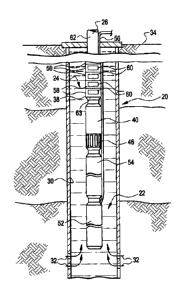
[0013] Referring generally to Figure 1, an embodiment of a well system 20
is
illustrated as installed in a wellbore 22. In this embodiment, well system 20
comprises a
pumping system 24 deployed by an appropriate deployment system 26. Depending
on
the pumping system application and the design of pumping system 24, deployment
system 26 may comprise coiled tubing, production tubing, cable or other
suitable
deployment systems. The pumping system 24 is designed for placement in
wellbore 22
proximate a geological formation 28 containing desirable production fluids,
such as
petroleum or other desired fluids. The wellbore 22 typically is drilled and
can be lined
with a wellbore casing 30. Perforations 32 are formed through wellbore casing
30 to
enable the flow of fluids between geological formation 28 and wellbore 22.
[0014] The wellbore 22 extends downwardly from a surface 34 which may be
the
surface of the earth or a seabed floor. Although wellbore 22 is illustrated as
generally
vertical, the wellbore also can be formed as a deviated wellbore depending on
the type of
well environment or well application in which system 20 is utilized. In the
example
illustrated, well system 20 extends down into wellbore 22 from a wellhead 36.
[0015] In the embodiment of Figure 1, pumping system 24 comprises a
submersible pump 38 and a separate, dedicated mixer 40 deployed on the
upstream side
of submersible pump 38. Pumping system 24 also may comprise additional
components,
e.g. component 42, depending on the type of pumping system utilized in a given
application. Additionally, regions of wellbore 22 may be isolated by one or
more
packers, such as packer 44 positioned above mixer 40. In a fluid production
operation,
the pumping system 24 is moved downhole to a desired location within a
wellbore 22,
and packer 44 is set against the surrounding wellbore wall, e.g. casing 30.
3
CA 02606619 2007-10-15
Attorney Docket No. 57.0756
[0016] Mixer 40 is particularly beneficial when used in producing fluids
that have
a relatively high gas-to-liquid ratio. For example, in the production of
petroleum, mixer
40 greatly facilitates production of fluids tending to have higher gas-to-oil
(GOR) ratios
that can otherwise hinder efficient production of the wellbore fluid. When
submersible
pump 38 is operated, fluid is drawn from wellbore 22 through an intake region
46 that
may be formed as part of dedicated mixer 40. As fluid moves into mixer 40
through
intake region 46, gas pockets, e.g. bubbles, can be drawn into mixer 40 with
the fluid.
[0017] Additionally, a portion of the gas phase can be separated from the
liquid
phase as the fluid is drawn through intake region 46. The separated gas phase
rises along
an annulus 48 surrounding pumping system 24 and can become trapped under, for
example, packer 44. As this gas accumulates, a relatively large gas structure
50 is formed
beneath packer 44. If this gas structure becomes sufficiently large, it can
interfere with
the intake of liquid through intake region 46 and further degrade the
operation of
pumping system 24. However, dedicated mixer 40 is designed to provide a
simple,
inexpensive tool that can be used to remove gas from gas structure 50 and/or
minimize
the gas pockets drawn into mixer 40 through intake region 46.
[0018] Referring generally to Figure 2, one embodiment of pumping system
24 is
illustrated in greater detail. In this embodiment, pumping system 24 comprises
an
electric submersible pumping system in which submersible pump 38 is a
centrifugal type
pump powered by a submersible motor 52. Submersible motor 52 may drive
submersible
pump 38 via a drive shaft extending through, for example, a motor protector 54
and
mixer 40. Electric power is provided to submersible motor 52 via a power cable
56 that
extends down along well system 20 from surface 34. In this type of embodiment,
submersible pump 38 comprises a plurality of stages 58 stacked on top of one
another, as
illustrated by dashed lines in Figure 2. Each stage 58 comprises an impeller
60, and the
multiple impellers 60 are rotated by submersible motor 52 to move well fluid
up through
wellbore 22 to a desired collection location. The well fluid can be produced,
for
example, through a tubing 62 or through the surrounding annulus.
4
CA 02606619 2007-10-15
Attorney Docket No. 57.0756
[0019] Dedicated mixer 40 is deployed upstream of the pumping components,
e.g. impellers 60, to deliver a well mixed, homogeneous fluid to an inlet 63
of
submersible pump 38. The configuration of dedicated mixer 40 and its placement
upstream of the pumping components enables the use of conventional submersible
pumps
without altering the impeller angles, forming holes through the impellers, or
using other
pump manipulation techniques that can increase the cost and reduce the pumping
efficiency of the overall system. In one embodiment, dedicated mixer 40 is
formed as a
separable component that is simply bolted into the electric submersible
pumping system
between, for example, submersible pump 38 and motor protector 54.
[0020] Without mixer 40, pumping system 24 is susceptible to the buildup
of the
gas on the suction side of impellers 60 which can lead to premature stalling
of individual
stages 58. Furthermore, without dedicated mixer 40, the well system is capable
of
operating in multiple stable states, as illustrated in Figure 3. Transitions
between the
states can be triggered by flow transients, e.g. flow instabilities or
perturbations. As
illustrated in Figure 3, a given pumping system without mixer 40 can operate
at high
liquid productivity states 64 or at low liquid productivity states 66 when
pumping fluid
having the same GOR rating, e.g. a GOR rating of 200 in the example provided
in Figure
3. The addition of mixer 40 enables gas structures within mixer 40 and/or
surrounding
mixer 40 to be minimized to an extent that operation of the overall pumping
system 24 is
not subjected to stalling of stages or transition between high and low
productivity states.
The dedicated mixer 40 homogenizes the mixture of liquid and gas phases prior
to entry
into submersible pump 38 and thus mitigates flow fluctuations at the inlet of
submersible
pump 38. Accordingly, the production of fluid can be maintained at the high
liquid
productivity rate 64, and the overall efficiency of the system 20 is
dramatically increased.
[0021] Examples of dedicated mixers 40 are illustrated in Figures 4 and
5.
Referring first to Figure 4, dedicated mixer 40 is positioned between
submersible pump
38 and a motive unit 68 that may comprise, for example, motor 52 and motor
protector
54. Motive unit 68 drives a plurality of impellers 60 positioned in stages of
pump 38.
Specifically, the impellers 60 are rotated via a drive shaft 70 that extends
through a mixer
body 72 of dedicated mixer 40.
CA 02606619 2007-10-15
Attorney Docket No. 57.0756
[0022] The dedicated mixer 40 illustrated in Figure 4 is designed to
capture
relatively large gas structures 50 that accumulate in the annulus 48
surrounding mixer
body 72. The gas structures 50 tend to form as well fluid is drawn into
dedicated mixer
40 through inlet region 46 and gas is separated from the fluid. The gas flows
upwardly
along annulus 48 and is trapped beneath packer 44. However, gas from gas
structure 50
surrounding mixer body 72 is drawn into dedicated mixer 40 through one or more
ports
74. Ports 74 extend through mixer body 72 to create a communication path
between the
interior of mixer body 72 and the surrounding annulus 48. As fluid moves
upwardly
through mixer 40 from inlet region 46, the flowing fluid creates a venturi
effect that
draws in gas from gas structure 50 through ports 74.
[0023] Gas drawn in through ports 74 is rigorously combined with the
fluid
flowing rapidly through the interior of mixer body 72 to provide a well mixed
fluid prior
to pumping of that fluid via impellers 60. Volumetric phase variations in the
annulus are
accommodated by the variable liquid level in annulus 48 while a relatively
constant rate
of gas flow is bled into mixer 40. Furthermore, the system is self stabilizing
because as
the liquid level in the annulus goes down, the pressure drop across ports 74
increases,
thus increasing the gas flow rate through ports 74. Additionally, the shape,
e.g.
curvature, of the inside surface of mixer body 72 proximate ports 74 can be
adjusted to
create more or less of a venturi effect. By mixing gas from gas structure 50
into the
produced fluid flow in a controlled manner before it can interfere with intake
of well
fluid through inlet region 46, detrimental impacts to pumping system 24 are
removed and
higher liquid productivity rates are maintained.
[0024] Another embodiment of dedicated mixer 40 is illustrated in Figure
5. In
this embodiment, the dedicated mixer 40 is designed to harness the difference
in slip
velocity between large gas structures and small bubble clouds. It is known
that large gas
structures slip relative to the liquid phase at relatively high speed. The
large gas
structures rise along the outside of mixer body 72 at a high rate.
Simultaneously, a
plurality of mixer elements 76 within mixer body 72 prevent internal formation
of large
gas structures; homogenize the fluid flow within mixer 40; and minimize phase
slip
before the fluid enters submersible pump 38.
6
CA 02606619 2007-10-15
=
Attorney Docket No. 57.0756
[0025] As well fluid enters dedicated mixer 40, large gas
structures rise along the
outside of mixer body 72 at a high rate. A plurality of small inlet ports 78
are arranged
along mixer body 72 to drain gas from the large gas structures, e.g. gas
structure 50, and
to distribute the gas along the interior of mixer body 72 where it is re-
homogenized
before being directed to submersible pump 38. In the embodiment illustrated,
the small
inlet ports 78 are distributed along the length of mixer body 72. This allows
gas to be
bled off from the gas pockets/slugs over an extended region as the gas slugs
slip past the
liquid phase in the annulus surrounding mixer 40. Phase slip is prevented
inside
dedicated mixer 40 due to the mixing of liquid and gas which redistributes the
gas phase
relative to the liquid phase prior to pumping of the fluid.
[0026] Mixer elements 76 may be stationary mixer elements that
create a mixing
motion as fluid flows through the interior of dedicated mixer 40. The energy
of the
flowing fluid effectively stirs or mixes the gas phase and liquid phase to
create a
homogeneous fluid that can be produced efficiently. Alternatively, mixer
elements 76
can be dynamic mixer elements that move within mixer body 72 to create a
mixing action
that redistributes the gas relative to the liquid. By way of example, such
dynamic mixer
elements can be coupled to shaft 70 and rotated via the power provided by
motive unit
68. The rotation of elements 76 prevents the formation of large bubbles and
eliminates
slip between the gas and liquid phases while creating a homogeneous fluid for
delivery to
submersible pump 38. In this example, the mixer elements provide a rigorous
mixing
action without a pumping action and present the mixed fluid to submersible
pump 38 for
movement upwardly along wellbore 22.
[0027] The specific components used in well system 20 can vary
depending on
the actual well application in which the system is used. Similarly, the
specific
configuration of dedicated mixer 40 can vary from one well application to
another. For
example, one or more dedicated mixers 40 can be incorporated into a variety of
electric
submersible pumping systems or other pumping systems susceptible to phase
separation
in high gas-to-liquid ratio fluids. Additionally, the fluid inlets, fluid
ports and/or mixer
elements can be changed to accommodate different applications or different
pumping
equipment.
7
CA 02606619 2007-10-15
Attorney Docket No. 57.0756
100281 Accordingly, although only a few embodiments of the present
invention
have been described in detail above, those of ordinary skill in the art will
readily
appreciate that many modifications are possible without materially departing
from the
teachings of this invention. Such modifications are intended to be included
within the
scope of this invention as defined in the claims.
8