Note: Descriptions are shown in the official language in which they were submitted.
CA 02607134 2007-11-01
WO 2006/116837 PCT/CA2006/000474
SURGICAL TOURNIQUET APPARATUS FOR MEASURING
LIMB OCCLUSION PRESSURE
FIELD OF THE INVENTION
[0001] This invention pertains to pneumatic tourniquet systems commonly used
for
stopping the flow of arterial blood into a portion of a surgical patient's
limb to facilitate the
performance of a surgical procedure, and for facilitating intravenous regional
anesthesia.
In particular, this invention pertains to pneumatic tourniquet apparatus for
measuring the
minimum pressure that must be applied to stop arterial blood flow into the
portion of the
limb to facilitate surgery
BACKGROUND OF THE INVENTION
[0002] Surgical tourniquet systems are commonly used to stop the flow of
arterial blood
into a portion of a patient's limb, thus creating a clear, dry surgical field
that facilitates the
performance of a surgical procedure and improves outcomes. A typical surgical
tourniquet
system of the prior art includes a tourniquet cuff for encircling a patient's
limb at a desired
location, a tourniquet instrument, and flexible tubing connecting the cuff to
the instrument.
In some surgical tourniquet systems of the prior art, the tourniquet cuff
includes an
inflatable portion, and the inflatable portion of the cuff is connected
pneumatically through
one or two cuff ports by flexible plastic tubing to a tourniquet instrument
that includes a
pressure regulator to maintain the pressure in the inflatable portion of the
cuff, when applied
to a patient's limb at a desired location, near a reference pressure that is
above a minimum
pressure required to stop arterial blood flow past the cuff during a time
period suitably long
for the performance of a surgical procedure. Many types of such pneumatic
surgical
tourniquet systems have been described in the prior art, such as those
described by McEwen
in U.S. Patent No. 4,469,099, No. 4,479,494, No. 5,439,477 and by McEwen and
Jameson
in U.S. Pat. No. 5,556,415 and No. 5,855,589.
[0003] To achieve better overall safety and performance, and in particular to
achieve
greater speed and accuracy in controlling the pressure in the tourniquet cuff,
some advanced
tourniquet systems include tourniquet cuffs that have two separate pneumatic
cuff ports, so
that two separate pneumatic passageways can be established between the
inflatable portion
of the cuff and the tourniquet instrument, by separately connecting flexible
plastic tubing
CA 02607134 2007-11-01
WO 2006/116837 PCT/CA2006/000474
2
between each port and the instrument. Such systems are often called dual-port
tourniquet
systems. In one such dual-port tourniquet system of the prior art, described
in U.S. Pat.
No. 4,469,099, the pneumatic pressure regulation elements within the
tourniquet instrument
communicate pneumatically with the inflatable portion of the cuff through one
port, and a
pressure sensor within the tourniquet instrument communicates pneumatically
with the
inflatable portion of the cuff through the second port. This configuration
enables more
accurate sensing, monitoring and regulation of the actual pressure in the
inflatable portion
of the cuff that encircles the patient's limb, in comparison to single-port
tourniquet systems.
In a typical single-port tourniquet system of the prior art, the tourniquet
cuff has only one
port and only one pneumatic passageway is established between the tourniquet
cuff and the
instrument. The actual cuff pressure must be sensed indirectly, through the
same tubing and
port that is used to increase, decrease and regulate the pressure in the cuff
during surgery.
As a result, in such a single-port tourniquet system of the prior art, the
accuracy and speed
of pressure regulation, and the accuracy of the sensed cuff pressure, are
affected by the
pneumatic flow resistance within the single port and within the flexible
plastic tubing that
pneumatically connects the port and cuff to the tourniquet instrument.
[0004] Many studies published in the medical literature have shown that the
safest
tourniquet pressure is the lowest pressure that will stop the flow of arterial
blood past a
specific cuff applied to a specific patient for the duration of that patient's
surgery. Such
studies have shown that higher tourniquet pressures are associated with higher
risks of
tourniquet-related injuries to the patient. Therefore, when a tourniquet is
used in surgery,
surgical staff generally try to use the lowest tourniquet pressure that in
their judgment is
safely possible.
[0005] It is well established in the medical literature that the optimal
guideline for setting
the pressure of a constant-pressure tourniquet is based on "Limb Occlusion
Pressure"
(LOP). LOP can be defined as the minimum pressure required, at a specific time
in a
specific tourniquet cuff applied to a specific patient's limb at a specific
location, to stop the
flow of arterial blood into the limb distal to the cuff. The currently
established guideline
for setting tourniquet pressure based on LOP is that an additional safety
margin of pressure
is added to the measured LOP, to account for physiologic variations and other
changes that
may be anticipated to occur normally over the duration of a surgical
procedure.
CA 02607134 2007-11-01
WO 2006/116837 PCT/CA2006/000474
3
[0006] Surgical staff can measure LOP manually by detecting the presence of
arterial
pulsations in the limb distal to a tourniquet cuff as an indicator of arterial
blood flow past
the cuff and into the distal limb. Such arterial pulsations can be defined as
the rhythmical
dilation or throbbing of arteries in the limb distal to the cuff due to blood
flow produced by
regular contractions of the heart. Detecting blood flow thus can be done using
palpation,
Doppler ultrasound or photoplethysmography to measure arterial pulsations. One
technique
for manual measurement of LOP based on monitoring arterial pulsations as an
indicator of
arterial blood flow is as follows: tourniquet cuff pressure is increased by an
operator slowly
from zero while monitoring arterial pulsations in the limb distal to the cuff
until the
pulsations can no longer be detected; the lowest tourniquet cuff pressure at
which the
pulsations can no longer be detected can be defined as the ascending LOP. A
second
manual technique is that an operator can slowly decrease tourniquet cuff
pressure while
monitoring to detect the appearance of arterial pulsations distal to the cuff;
the highest
pressure at which arterial pulsations are detected can be defined as the
descending LOP.
The accuracy of such manual measurements of LOP is very dependent on the
sensitivity,
precision and noise immunity of the technique for detecting and monitoring
arterial
pulsations, and on operator skill, technique and consistency. Under the best
circumstances
considerable elapsed time is required on the part of a skilled, experienced
and consistent
operator, using a sensitive and precise technique for detecting and monitoring
pulsations as
an indicator of distal blood flow, to accurately measure LOP by manual means.
[0007] Some surgical tourniquet systems of the prior art include means to
measure LOP
automatically. Prior-art tourniquet apparatus having automatic LOP measurement
means
are described by McEwen in US Pat. No. 5,439,477 and by McEwen and Jameson in
US
Pat. No. 5,556,415. Such prior-art systems have included blood flow
transducers that
employ a photoplethysmographic principle to sense blood flow in the distal
limb, although
other transducers have been suggested in the prior art to measure blood flow
based on other
principles. A blood flow transducer employing the photoplethysmographic
principle uses
light to indicate the volume of blood present in a transduced region,
consisting of a
combination of a residual blood volume and a changing blood volume resulting
from
arterial pulsations. An additional pressure margin based on recommendations in
published
surgical literature is added to the automatically measured LOP to provide a
"Recommended
Tourniquet Pressure" (RTP), as a guideline to help the surgical staff select
the lowest
CA 02607134 2007-11-01
WO 2006/116837 PCT/CA2006/000474
4
tourniquet pressure that will safely stop arterial blood flow for the duration
of a surgical
procedure. Such prior-art systems allow the surgical staff to select the RTP,
based on LOP,
as the tourniquet pressure for that patient or to select another pressure
based on the
physician's discretion or the protocol at the institution where the surgery is
being
performed.
[0008] Despite their potential to recommend near-optimal settings of surgical
tourniquet
pressures for individual patients, prior-art surgical tourniquet systems that
include means for
automatic measurement of LOP have demonstrated limitations of performance that
have
prevented their widespread acceptance and routine use. The limitations are
primarily in
four areas: safety, probability of successful LOP measurement, speed of LOP
measurement,
and accuracy of LOP measurement.
[0009] Regarding safety, it is desirable during LOP measurement that the
tourniquet cuff
pressure not rise significantly above the pressure required to stop blood flow
past the cuff
for a significant period of time. This is because it is well established that
the possibility of
tourniquet-related injuries increases if tourniquet cuff pressure increases
substantially. For
this reason, prior-art tourniquet apparatus that measures LOP by descending
from a high
cuff pressure are considered to be less desirable than tourniquet apparatus
that measures
LOP by ascending from a low pressure. Also regarding safety, it is desirable
that LOP
measurements be made as quickly as possible, while still assuring that the
resulting LOP
measurement is sufficiently accurate to allow setting the tourniquet pressure
based on the
measured LOP. Speed of LOP measurement is desirable for three reasons related
to safety
and performance: first, it is well established that longer tourniquet times
are associated with
a higher possibility of tourniquet-related injuries; second, during LOP
measurement, if
venous outflow of blood from the limb is restricted by a pressurized
tourniquet cuff for an
excessively long period of time, then pooling of blood in the distal limb from
arterial inflow
may occur, possibly leading to passive congestion of the limb from residual
blood that may
be hazardous; and third, any continuing increase of residual blood in the
distal limb over an
extended measurement period may lead to measurement error in
photoplethysmographic
blood flow transducers, because such transducers inherently provide one
indication of the
combination of residual blood volume and varying blood volume resulting from
arterial
pulsations in the transduced portion, thus lengthening the time for successful
completion of
LOP measurement, or making successful LOP measurement impossible.
CA 02607134 2007-11-01
WO 2006/116837 PCT/CA2006/000474
[0010] Experience with manual LOP measurement, and with prior-art tourniquet
apparatus having LOP measurement capability, has shown that it is not possible
in practice
to measure the LOP of all patients. This is because the quality and magnitude
of arterial
blood flow measured by a blood flow transducer distal to the tourniquet cuff
may not be
sufficient in some patients for measurement or analysis, due to a variety of
anatomic and
physiologic factors. For such patients, the physician must revert to a
standard tourniquet
pressure setting based on the physician's discretion. No prior-art tourniquet
system includes
means to characterize the quality and magnitude of blood flow distal to the
tourniquet cuff
measured by a blood flow transducer, in order to quickly identify those
patients and
situations in which LOP measurement is unlikely to be successfully completed.
As a result,
considerable time may be taken in the surgical setting in an attempt to
measure LOP which
is ultimately unsuccessful as well as time-consuming.
[0011] Even for patients in whom LOP measurement is possible, the time
required by
tourniquet systems known in the prior art to successfully complete automatic
LOP
measurements may be considerable. In addition to the safety-related
considerations
described above, the extended time required for LOP measurement by prior-art
tourniquet
systems may significantly disrupt or delay normal activities in the operating
room, and thus
affect the efficiency of surgery. This is in part because the patient's
operative limb must
remain motionless during the measurement period, to avoid the introduction of
variations in
pneumatic cuff pressure and the introduction of noise due to movement of the
distal blood
flow transducer relative to the limb. In prior-art apparatus for measuring
LOP, the reference
pressure for the tourniquet cuff is typically increased from zero in many
predetermined
increments of increasing pressure. After each such predetermined increment or
step of the
reference pressure, time is required to allow the actual increased pressure
within the
tourniquet cuff to stabilize before measurements can be taken from the distal
blood flow
transducer and related to actual cuff pressure. Substantially increasing the
predetermined
step size in such prior-art systems might increase the speed of LOP
determination, but could
also decrease the accuracy of LOP measurement significantly. Thus the total
time required
for sufficiently accurate LOP measurement in prior-art systems can be
substantial, and
includes the time required to increase the reference pressure in many
predetermined steps
from zero, the time required to allow the actual cuff pressure to stabilize
after each step, and
the time required to take a measurement from the distal blood flow transducer
at each step,
CA 02607134 2007-11-01
WO 2006/116837 PCT/CA2006/000474
6
until a LOP measurement is successfully made or until an arbitrary maximum
pressure limit
is reached without LOP being measured.
[0012] The accuracy of LOP measurements by prior-art tourniquet apparatus may
be
affected by two additional sources of error. First, because of the substantial
time periods
often required to measure LOP by prior-art tourniquet apparatus, error may be
introduced
into the LOP measurement due to accumulation of residual blood in the limb
distal to the
tourniquet cuff. This gradual accumulation of residual blood due to blocking
of venous
outflow by the tourniquet cuff can reduce the magnitude of the pulsations in
blood volume
that are associated with the rhythmical dilation or throbbing of the distal
arteries over the
duration of each cardiac cycle, from heartbeat to heartbeat. Also, such an
increasing
volume of residual blood in the distal limb during a measurement interval can
cause a
gradual change in the mean blood flow signal from a photoplethysmographic
transducer
during the period, for reasons described above. Such a gradual change may make
valid
arterial pulsations indicating arterial blood flow difficult or impossible to
detect, and
reduces the maximum possible amplification of the signal from the distal blood
flow
transducer, thus reducing the accuracy of subsequent analysis. A second source
of error in
LOP measurement by prior-art tourniquet apparatus results from movement of the
patient's
limb and movement of the distal blood flow transducer relative to the attached
limb, either
of which could mask valid arterial pulsations indicating blood flow or could
be
misinterpreted as valid arterial pulsations.
[0013] There is a need for improved surgical tourniquet apparatus for
measuring LOP, to
overcome the above-described limitations of prior-art tourniquet systems, so
that such
apparatus will be suitable for routine use in all surgical procedures
involving a tourniquet.
To be routinely useful in this context, apparatus for measuring LOP
automatically should
not introduce secondary hazards associated with the measurement of LOP, should
have a
high probability of successful completion after LOP measurement is initiated,
should
complete LOP measurement sufficiently fast so that the measurement of LOP does
not
disrupt or unduly delay normal activities in the operating room, and should
result in an LOP
measurement that is accurate within surgically acceptable expectations so that
it can be used
as the basis for optimal setting of tourniquet pressure. The present invention
addresses the
need for improved surgical tourniquet apparatus for measuring LOP.
CA 02607134 2013-02-04
6a
SUMMARY OF THE INVENTION
[0013a] The present invention provides a tourniquet apparatus for
rapidly and
accurately measuring a patient's limb occlusion pressure comprising: an
inflatable
tourniquet cuff for encircling a limb at a location; a tourniquet instrument
releasably
connectable to the cuff and including pressure sensing means for producing a
cuff pressure
signal indicative of the level of pressure in the cuff, pressure regulation
means
communicating with the cuff and responsive to the cuff pressure signal for
regulating the
pressure in the cuff near a reference pressure level, blood flow transducing
means adapted
for applying to a portion of the limb distal to the cuff to transmit light
through the portion of
the limb, thereby to produce a blood flow signal indicative of blood flow in
the portion,
compensation means for compensating for reduction of the light transmission
through the
portion of the limb that is attributable to increases in the volume of venous
blood in the
portion of the limb by increasing the intensity of the light to maintain the
level of the blood
flow signal near a target level; and limb occlusion pressure means responsive
to the blood
flow signal and the cuff pressure signal and operable for detecting arterial
pulsations of
blood flow, for increasing the reference pressure level in synchrony with the
arterial
pulsations and for producing a limb occlusion pressure value indicative of the
lowest level
of pressure in the cuff at which the magnitude of the arterial pulsations is
less than a
minimum detection threshold.
[0013b] The present invention also provides a tourniquet apparatus
for rapidly
and accurately measuring a patient's limb occlusion pressure comprising: a
tourniquet cuff
for encircling a patient's limb at a location on the limb and including an
inflatable portion
that communicates pneumatically with a first cuff port and that communicates
pneumatically with a second cuff port independently of the first cuff port; a
tourniquet
instrument that is releasably connectable to the first and second cuff ports
to establish first
and second pneumatic passageways between the tourniquet cuff and the
tourniquet
instrument, wherein the tourniquet instrument includes pressure sensing means
communicating with the first pneumatic passageway for producing a cuff
pressure signal
indicative of the level of pressure in the cuff, pressure regulation means
communicating
CA 02607134 2013-02-04
6b
with the second pneumatic passageway and responsive to the cuff pressure
signal for
regulating the pressure in the cuff near a reference pressure level, blood
flow signal
processing means for transmitting light through a portion of the limb and
detecting the
transmitted light for producing blood flow signals indicative of blood flow
past the cuff and
for processing the signals into non-pulsatile components as well as an
arterial pulsations,
and limb occlusion pressure means for detecting the non-pulsatile components
and the
arterial pulsations for increasing the reference pressure level in synchrony
with the arterial
pulsations, and for producing a limb occlusion pressure value indicative of
the lowest cuff
pressure at which the magnitude of the arterial pulsations is less than a
minimum detection
threshold and for compensating for increases in the volume of venous blood in
the patient's
limb distal to the cuff that would, in the absence of compensation, reduce at
least the level
of the non-pulsatile component of the blood flow signal by increasing the
intensity of the
light to maintain the level of the blood flow signals near a target level.
CA 02607134 2007-11-01
WO 2006/116837 PCT/CA2006/000474
7
BRIEF DESCRIPTION OF THE DRAWINGS
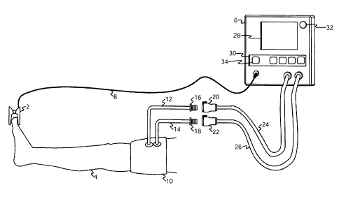
[0014] FIG. 1 is a pictorial representation of the preferred embodiment in a
surgical
application.
[0015] FIG. 2 is a block diagram of the preferred embodiment.
[0016] FIG. 3 is an illustration that shows increases in the level of the
cuff reference
pressure in synchrony with arterial pulsations detected during the measurement
of limb
occlusion pressure by the preferred embodiment.
[0017] FIG. 4 and FIG. 5 are flow charts depicting the sequence of operations
performed
by the preferred embodiment during measurement of limb occlusion pressure.
DETAILED DESCRIPTION OF THE PREFERRED EMBODIMENT
[0018] The embodiment illustrated is not intended to be exhaustive or limit
the invention
to the precise form disclosed. It is chosen and described in order to explain
the principles of
e invention and its application and practical use, and thereby enable others
skilled in the
art to utilize the invention.
Hardware
[0019] FIG. 1 shows blood flow transducer 2 applied to a digit of patient limb
4 and
connected to instrument 6 via multi-conductor shielded cable 8. Blood flow
transducer 2 is
positioned on patient limb 4 at a location that is distal to pressurizing cuff
10 which is also
shown applied to patient limb 4. This configuration permits blood flow
transducer 2 to
detect blood flow in patient limb 4 and changes in blood flow that occur in
patient limb 4 as
a result of the pressurization of cuff 10. Blood flow transducer 2 is used by
instrument 6
when instrument 6 is performing automatic measurements of limb occlusion
pressure
(LOP). LOP has been defined above to be the minimum pressure required, at a
specific
time in a specific tourniquet cuff applied to a specific patient's limb at a
specific location, to
stop the flow of arterial blood into the limb distal to the cuff.
[0020] Cuff 10 is pneumatically connectable to instrument 6. The inflatable
portion of
pressurizing cuff 10 has two separate pneumatic connections and is generally
similar in
design and construction to the cuffs described by McEwen in U.S. Patent No.
5,741,295,
No. 5,649,954, No. 5,484,831 and by Robinette-Lehman in U.S. Patent No.
4,635,635. Cuff
is adapted for use in a sterile surgical field in an operating room
environment by being
formed of materials that can withstand, and that can be sterilized by,
techniques normally
used to sterilize medical devices to a level of sterility that allows them to
be safely used
CA 02607134 2007-11-01
WO 2006/116837 PCT/CA2006/000474
8
within a sterile surgical field. Cuff 10 is a dual-port cuff, and separate
pneumatic
passageways to the inflatable portion of cuff 10 are provided by cuff port 12
and cuff port
14 so that each passageway is independent of the other. In FIG. 1 cuff port 12
and cuff port
14 are of sufficient length to allow pneumatic connections to cuff 10 to be
made outside of a
sterile surgical field. Cuff port 12 and 14 are fitted with male locking
connectors 16 and 18
(DSM2202, Colder Products Company, St. Paul, MN) respectively, and mate to
form
releasable pneumatic connections with female locking connectors 20 and 22
(PMC1704,
Colder Products Company, St. Paul, MN). For clarity, the connectors
illustrated in FIG. 1
are shown disconnected; in the following description of the preferred
embodiment the
connectors are mated and form part of the pneumatic passageways between
instrument 6
and cuff 10. Pneumatic connections from instrument 6 to cuff 10 are made by
flexible
plastic tubing 24 and 26 which are fitted with female locking connectors 20
and 22
respectively.
[0021] As can be seen in FIG. 1, instrument 6 has a user interface consisting
of graphic
display panel 28, keypad 30, and visual alarm indicator 32. Display panel 28
is employed
for the selective display of any of the following alphanumeric information:
limb occlusion
pressures and recommended tourniquet pressures as measured and calculated by
instrument
6; actual cuff pressures as measured by instrument 6; reference or "set" cuff
pressure levels,
alarm reference "limits" or values; alphanumeric alarm messages describing
detected alarm
conditions and other information required for the operation of instrument 6.
[0022] Keypad 30 provides a means for a user of instrument 6 to control the
operation of
instrument 6. Keypad 30 includes a limb occlusion pressure measurement (LOP)
key 34,
which when depressed will initiate the measurement of LOP as described further
below.
Keypad 30 also has an "inflate" key to initiate the inflation of cuff 10, a
"deflate" key to
initiate the deflation of cuff 10, and other keys to permit the user of
instrument 6 to adjust
the reference pressure level and set inflation time alarm limits.
[0023] Visual alarm indictor 32 is a bright red light emitting diode (LED)
which is
activated by instrument 6 in response to detected alarm conditions. Instrument
6 also
signals the presence of an alarm condition by generating an audible tone to
further alert the
user to the presence of an alarm condition and displays alarm text messages
describing the
alarm condition on display panel 28. One example of a detected alarm condition
that
CA 02607134 2007-11-01
WO 2006/116837 PCT/CA2006/000474
9
requires the user's attention is the accidental removal of blood flow
transducer 2 during a
limb occlusion pressure measurement.
[0024] Referring to the block diagram of instrument 6 shown in FIG. 2,
controller 36
comprises a microcontroller (MC68HC16Z1, Freescale Semiconductor, Austin, TX),
associated memory and control software, analog and digital peripheral
interface circuitry,
and other necessary support components.
[0025] As shown in FIG. 2, pneumatic pump 38 (KNF Neuberger, Inc., Trenton,
NJ) is
pneumatically connected to reservoir 40 by tubing 42. In response to control
signals from
controller 36, pump 38 operates to pressurize reservoir 40. Reservoir pressure
transducer 44
is pneumatically connected by tubing 46 to reservoir 40 and generates a
reservoir pressure
signal. The reservoir pressure signal is communicated to controller 36.
Controller 36 acts
to maintain the pressure in reservoir 40 near a reservoir pressure level.
Controller 36 sets
the reservoir pressure level to a pressure above the reference pressure level
set by the user
of instrument 6 or automatically by controller 36 during a limb occlusion
pressure
measurement; the reservoir pressure level is set to a level significantly
greater than the
reference pressure level, typically 100 mmHg. Controller 36 in response to the
reservoir
pressure level and the reservoir pressure signal activates pump 38 to maintain
the level of
the reservoir pressure signal near the reservoir pressure level.
[0026] Inflation valve 48 (EVO-3-12V, Clippard Instrument Laboratory,
Cincinnati, OH)
is configured as a two position normally closed valve. One side of the valve
is
pneumatically connected via tubing 50 to reservoir 40 the other side of the
valve is
connected to cuff 10 via the pneumatic passageway formed by manifold 52,
tubing 24,
connectors 20 and 16 and cuff port 12. When energized by controller 36,
inflation valve 48
moves to the open position and allows pressurized gas to flow from reservoir
40 to cuff 10,
thereby increasing the pressure of gas in the inflatable portion of cuff 10.
[0027] Deflation valve 54 (EVO-3-12V, Clippard Instrument Laboratory,
Cincinnati,
OH) is configured as a two position normally closed valve. One side of the
valve is
pneumatically connected to cuff 10 via the pneumatic passageway formed by
manifold 52,
tubing 24, connectors 20 and 16 and cuff port 12, the other side is open to
atmosphere.
When energized by controller 36, deflation valve 54 moves to the open position
and allows
pressurized gas to flow from cuff 10 to atmosphere, thereby decreasing the
pressure of gas
in the inflatable portion of cuff 10.
CA 02607134 2007-11-01
WO 2006/116837 PC T/CA2006/000474
[0028] In the preferred embodiment the inflation and deflation valves share a
common
pneumatic connection with a port of cuff 10. It will be appreciated that other
configurations
of the inflation and deflation valves may be employed. For example, it may be
desirable to
have the inflation valve communicate separately with one port of cuff 10 and
to have the
deflation valve communicate separately with the other port of cuff 10. This
possible
configuration may be desirable if the inflatable portion of cuff 10 includes a
pressure
transducer that communicates wirelessly with instrument 6 to directly indicate
the pressure
in cuff 10.
[0029] Cuff pressure transducer 56 is pneumatically connected to cuff 10 via
the
pneumatic passageway formed by tubing 58, tubing 26, connectors 22 and 18 and
cuff port
14 and generates a cuff pressure signal which is communicated to controller
36. The
separate independent pneumatic connection between the inflatable portion of
cuff 10 and
cuff pressure transducer 56 provides for an accurate indication of the actual
pressure of gas
within cuff 10 at any time. Controller 36 is able to resolve changes in the
cuff pressure
signal as small as 0.15 mmHg.
[0030] As noted above, controller 36 will, in response to generated alarm
signals alert the
user of an alarm condition by activating visual alarm indicator 32 and
producing audible
tones. Speaker 60 is connected to controller 36, and electrical signals having
different
frequencies to specify different alarm signals and conditions are produced by
controller 36
and converted to audible sound by loudspeaker 60.
[0031] Power supply 62 connects to an external AC supply and provides
regulated DC
power for the normal operation of all electronic components of instrument 6.
Power supply
62 may also include a battery to enable instrument 6 to continue to operate in
the absence of
an external AC supply.
Pressure Regulation.
[0032] A user of instrument 6 may use keypad 30 to select a reference pressure
level; this
is the pressure of gas that instrument 6 will attempt to maintain in the
inflatable portion of
cuff 10 when cuff 10 is inflated. Controller 36 will generate high or low
pressure alarm
signals if the pressure in cuff 10 cannot be maintained near the selected
reference pressure
level. If the cuff pressure level exceeds the reference pressure level by 15
mmHg a high
pressure alarm signal will be generated by controller 36. If the cuff pressure
level falls
CA 02607134 2007-11-01
WO 2006/116837 PCT/CA2006/000474
11
below the reference pressure level by 15 mmHg a low pressure alarm signal will
be
generated by controller 36.
100331 When controller 36 detects that the "inflate" key on keypad 30 has been
depressed
by a user of instrument 6, controller 36 operates to inflate cuff 10 to a
pressure near the
selected reference pressure level and to then regulate the pressure in cuff 10
near the
reference pressure level until such time that controller 36 detects that the
"deflate" key on
keypad 30 has been depressed by a user of instrument 6. Controller 36 may also
inflate,
adjust the reference pressure level, and deflate cuff 10 automatically during
a limb
occlusion pressure measurement as described further below.
[0034] To inflate and regulate the pressure in cuff 10 controller 36
includes a pressure
regulator; the pressure regulator in the preferred embodiment is implemented
as a control
algorithm that operates as described below. At regular predetermined
regulation intervals of
40 ms controller 36 computes a pressure error signal. The pressure error
signal corresponds
to the difference between the reference pressure level and the cuff pressure
level. Controller
36 uses the pressure error signal as a term in a proportional integral control
algorithm to
calculate activation time intervals for inflation valve 48 and deflation valve
54. To increase
the gas pressure in cuff 10 when the cuff pressure signal is below the
reference pressure
level, the activation time interval for deflation valve 54 is set to zero and
the activation time
interval for inflation valve 48 is proportional to the magnitude of the
pressure error signal
and the integral of the pressure error signal. To decrease the gas pressure in
cuff 10 when
the cuff pressure signal is above the reference pressure level, the activation
time interval for
inflation valve 48 is set to zero and the activation time interval for
deflation valve 54 is
proportional to the magnitude of the pressure error signal and the integral of
the pressure
error signal. Controller 36 limits the maximum valve activation time intervals
of valve 48
and valve 54 to the regulation interval time (40 ms). It will be appreciated
by those skilled
in the art that alternate pressure regulation algorithms could be employed to
control the
activation of inflation valve 48 and deflation valve 54 in response to a cuff
pressure signal
and a reference pressure level, or that proportional valves could be used
instead of the
valves used in the preferred embodiment. Also it will be appreciated that a
regulator has a
response time, consisting of the amount of time required for the pressure of
gas in the cuff
to reach the level of the reference pressure level after a new reference
pressure level has
been selected. The regulator response time will depend upon the magnitude of
the change
CA 02607134 2007-11-01
WO 2006/116837 PCT/CA2006/000474
12
in reference pressure level, the volume of cuff 10 and the characteristics of
the pneumatic
components in instrument 6 and the specifics of the control algorithm used.
Thus the actual
pressure of gas in cuff 10 may differ substantially from the reference
pressure level for a
varying period of time after a change in the reference pressure level.
[0035] In order to correctly regulate the pressure of gas in cuff 10 at a
pressure near the
cuff pressure reverence level and correctly indicate over and under pressure
alarm
conditions, controller 36 must have available an accurate indication of the
pressure within
the inflatable portion of cuff 10. In the preferred embodiment the accurate
measurement of
the pressure of gas in cuff 10 is facilitated by cuff pressure transducer 56
and the direct
pneumatic connection between the inflatable portion of cuff 10 and transducer
56. The
connection between the inflatable portion of cuff 10 and transducer 56 is made
by tubing
58, flexible plastic tubing 26, connectors 22 and 18, and cuff port 14. An
accurate
measurement of the pressure of gas in cuff 10 at any time is also critical to
the ability of
instrument 6 to accurately and rapidly measure LOP, as explained below.
Blood Flow Transducer and Signal Processing
100361 Referring again to FIG. 2, the internal components of blood flow
transducer 2 are
shown in detail. Blood flow transducer 2 of the preferred embodiment employs
the
principle of photoplethysmography and is adapted for positioning on the limb
distal to the
tourniquet cuff, although it will be appreciated that other types of blood
flow transducers
employing other principles may be used, and it will be appreciated that some
types of blood
flow transducers may be physically integrated into the structure of a
tourniquet cuff. In the
preferred embodiment, blood flow transducer 2 has a hinged plastic housing
that is
configured for application to a digit of a limb. Blood flow transducer 2 may
be applied to a
finger or thumb of the hand or a toe of the foot. Transducer 2 includes an
infrared light
emitting diode (IRLED) 64 and a photodiode 66 which is sensitive to the
wavelength of
light emitted by IRLED 64. In the preferred embodiment an IRLED with a
wavelength of
915 nm is employed. Within blood flow transducer 2 IRLED 64 and photodiode 66
are
positioned directly opposite each other such that light emitted by IRLED 64 is
readily
detected by photodiode 66. When applied to a digit IRLED 64 illuminates a
volume of
tissue and photodiode 66 detects the light that is transmitted through this
volume of tissue.
[0037] IRLED 64 is connected via multi-conductor cable 8 to adjustable
constant current
source 68. The intensity of light emitted by IRLED 64 is proportional to the
amount of
CA 02607134 2007-11-01
WO 2006/116837 PCT/CA2006/000474
13
electrical current that flows through IRLED 64. Controller 36 communicates
with
adjustable constant current source 68 to set the level of current that flows
through IRLED
64 and thereby the intensity of light emitted by IRLED 64. In the preferred
embodiment the
current source 68 can be adjusted to supply electrical current ranging from 0
to 100
milliamps in steps of 0.1 milliamps by controller 36.
[0038] Photodiode 66 generates an electrical current that is linearly
proportional to the
intensity of light that strikes the light sensitive area of photodiode 66.
Photodiode 66 is
connected by multi-conductor cable 8 to blood flow signal processor 70. Signal
processor
70 amplifies, filters, and digitizes the current generated by photodiode 66 to
produce a
blood flow signal that is representative of the intensity of light that
strikes photodiode 66.
The characteristics of photodiode 66 and the electronic circuits within signal
processor 70
determine the minimum and maximum light intensities that the blood flow signal
can
represent. As described below, the preferred embodiment operates to maintain
the level of
the blood flow signal within the dynamic range of signal processor 70.
[0039] When blood flow transducer 2 is applied to a digit of a patient's
limb the intensity
of light reaching photodiode 66 is dependent upon a number of factors. These
factors are
the initial intensity of the light emitted by IRLED 64; the amount of light
absorbed by the
skin pigmentation, tissue and bone of the digit; the amount of light absorbed
by venous
blood and non-pulsatile arterial blood and pulsatile arterial blood; and the
optical path
length between IRLED 64 and photodiode 66. When cuff 10 is deflated, a
relatively
constant amount of light is absorbed by the skin pigmentation, bone other
tissue, venous
blood and the non-pulsatile part of the arterial blood. This aggregate non-
pulsatile
component of the blood flow signal, illustrated as non-pulsatile signal 302 in
FIG. 3, is
detected and measured by non-pulsatile level detector 72. Non-pulsatile level
detector 72
communicates to controller 36 the level of non-pulsatile signal 302.
[0040] During each cardiac cycle the diameters of the arteries and
arterioles alternately
increase and decrease in response to arterial blood flow pulsations. This
alternating
increase and decrease in diameters affects the optical path length between
IRLED 64 and
photodiode 66 and produces a rhythmical and alternating variation in the
intensity of light
transmitted through the digit that is in synchrony with each cardiac cycle.
Typically, this
rhythmical and alternating variation of intensity is 1-2 percent of the total
amount of light
transmitted through the volume of tissue, and results in the production by
signal processor
CA 02607134 2007-11-01
WO 2006/116837
PCT/CA2006/000474
14
70 of a blood flow signal having alternating variations as illustrated in FIG.
3. Arterial
pulsation detector 74 detects an arterial pulsation by detecting the
occurrence of the
alternating variation in the blood flow signal from signal processor 70 that
occurs during
each cardiac cycle, and further determines the relative magnitude of each
detected arterial
pulsation by determining the difference between the minimum and maximum of
each
alternating variation of the blood flow signal, as illustrated in FIG. 3.
[0041] FIG. 3 illustrates non-pulsatile signal 302, blood flow signal 304,
and arterial
pulsations of magnitudes 306, 308 and 310 that decrease as cuff pressure 312
increases in
response to increases in reference pressure level 314. FIG. 3 also illustrates
that cuff
pressure 312 may differ significantly from reference pressure level 314 for
varying periods
of time after changes in reference pressure level 314. Finally, FIG. 3
illustrates that, in the
preferred embodiment, changes in reference pressure level 314 are only made in
synchrony
with arterial pulsations detected by arterial pulsation detector 74, as
explained further
below. Synchronizing any change in reference pressure level 314 to detected
arterial
pulsations is an important characteristic of the preferred embodiment that
greatly increases
the speed of LOP measurement in comparison to prior-art apparatus in which
increases in
reference pressure levels are made at arbitrary, unsynchronized times.
[0042] The magnitude is affected by the intensity of light emitted by IRLED
64.
Generally, as the intensity of light emitted by IRLED 64 increases, the volume
of tissue
illuminated by IRLED 64 increases which results in an increase in the
magnitude of the
alternating and rhythmical variation of the blood flow signal as more arteries
and arterioles
are illuminated in the optical path between IRLED 64 and photodiode 66.
[0043] The optical path length through the volume of tissue between IRLED 64
and
photodiode 66 is also affected by any change in diameter of the venules and
the amount of
venous blood in the tissue. When cuff 10 is pressurized to a level that is
greater than that
required to occlude venous blood from flowing out of the limb but still at a
level that allows
arterial blood to flow into the limb there is an increase in the volume of
venous blood
present in the limb and a corresponding increase in the diameter of the
venules. This
increase in diameter increases the optical path length through the volume of
tissue and
results in a decrease in the amount of light detected by photodiode 66. This
decrease in
light intensity happens gradually, but may be substantial, resulting in
reductions of up to
three orders of magnitude of the light transmitted through the volume of
tissue. In the
CA 02607134 2007-11-01
WO 2006/116837 PCT/CA2006/000474
preferred embodiment this change in the intensity of light transmitted through
the volume of
tissue is compensated for by an increase in the intensity of IRLED 64, as
described further
below. In some circumstances described further below it may not be possible to
compensate for this magnitude of change in intensity as IRLED 64 has an upper
limit to the
intensity of light that it can produce.
[0044] Each cardiac cycle that occurs when cuff 10 is at a pressure that
partially or
completely stops venous outflow, but not arterial inflow, results in an
increase in the
amount of venous blood in the volume of tissue illuminated by IRLED 64. It is
important to
minimize the time that cuff 10 is at these pressures because the accumulation
of venous
blood may be hazardous, as explained above. It is also important that this
time be
minimized to insure that the photoplethysmographic blood flow signal remains
in a region
that is within the dynamic range of IRLED 64 to illuminate the tissue, and
within the
dynamic range of the electronic circuits used to detect and process the signal
from
photodiode 66. The preferred embodiment acts to minimize the time that cuff 10
is at these
pressures when attempting to make a measurement of LOP by assessing during an
initialization period whether such an attempted measurement is likely to be
successful, as
follows. In the initialization period, if a blood flow signal cannot be
detected by signal
processor 70, or if alternating rhythmical variations of the blood flow signal
characterizing
arterial pulsations above a predetermined minimum initial magnitude cannot be
detected by
arterial pulsation detector 74, then controller 36 increases the intensity of
IRLED 64 by
adjusting the current to IRLED 64 by means of adjustable constant current
source 68 in an
effort to increase the magnitude of the blood flow signal to a level suitable
for analysis. If
this adjustment by current source 68 still does not result in a blood flow
signal having
variations greater than the predetermined minimum initial magnitude, then
controller 36
promptly terminates the attempt to measure LOP and produces an appropriate
indication
perceptible to the operator. In this way, the preferred embodiment minimizes
the duration
of an attempt to measure LOP that may delay the start of surgery, and that may
cause
venous blood pooling, if that measurement of LOP is unlikely to be
successfully completed,
and allows the operator to promptly select another reference pressure level
for the
tourniquet system that is not based on LOP.
[0045] If an attempt to measure LOP has not been terminated during the
initialization
period, arterial pulsation detector 74 continues to analyze the blood flow
signal from signal
CA 02607134 2007-11-01
WO 2006/116837 PCT/CA2006/000474
16
processor 70 to detect the occurrence of each alternating rhythmical variation
above a
minimum detection threshold that characterizes an arterial pulsation of blood
flow, and to
indicate to controller 36 the magnitude of the difference between the maximum
and
minimum of the alternating rhythmical variation, as illustrated by magnitudes
306, 308 and
310 in FIG. 3. Each magnitude is representative of the amount of arterial
blood flowing
into the volume of tissue between IRLED 64 and photodiode 66 during the period
of each
cardiac cycle. To be correctly identified as an arterial pulsation of blood
flow, the
magnitude must exceed the minimum detection threshold. The minimum detection
threshold of arterial pulsation detector 74 is initially set to a
predetermined threshold, and
may subsequently be set by controller 36 to another threshold.
[0046] When an arterial pulsation is detected by arterial pulsation
detector 74, the time of
occurrence is communicated to controller 36, and pulsation detector 74 enters
a refractory
time period immediately after the detected occurrence. During the refractory
time period,
pulsation detector 74 is non-responsive to the blood flow signal from signal
processor 70.
This non-responsiveness of pulsation detector 74 to the blood flow signal
during the
refractory time period allows controller 36 to make adjustments to the level
of the current
supplied by adjustable constant current source 68 to IRLED 64 while preventing
pulsation
detector 74 from erroneously analyzing any noise or artifact in the blood flow
signal
resulting from the adjustments to the level of current to IRLED 64. During the
measurement of LOP, controller 36 typically sets the refractory time period of
pulsation
detector 74 to be equal to 75 percent of the time between successively
detected arterial
pulsations. Depending on the time between successive pulsations, the duration
of the
refractory time period may be adjusted by controller 36 from a predetermined
initial time of
350 milliseconds to a predetermined maximum time of 1200 milliseconds.
Limb Occlusion Pressure Measurement
[0047] To automatically measure the limb occlusion pressure, controller 36
must
determine the minimum pressure required in cuff 10 to prevent arterial blood
flow into
patient limb 4 distal to the location of cuff 10. As described in detail
below, controller 36
does this by analyzing signals produced by non-pulsatile level detector 72, by
arterial
pulsation detector 74 and by blood flow signal processor 70 while increasing
the pressure in
cuff 10 to a pressure level at which arterial blood flow is no longer
detectable above a
minimum detection threshold.
CA 02607134 2007-11-01
WO 2006/116837
PCT/CA2006/000474
17
[0048] To enable a better understanding of the sequence of operations
completed and
decisions made by controller 36 during the automatic measurement of limb
occlusion
pressure a flow chart is provided in FIG. 4 and FIG. 5.
[0049] Referring to the flow chart in FIG. 4, when controller 36 detects that
LOP key 34
on keypad 30 has been depressed (402) it first determines if cuff 10 is
already inflated and
being regulated as would be the case if a user of instrument had previously
activated the
inflate key on keypad 30 (404). Controller 36 only responds to LOP key 34 to
initiate an
LOP measurement sequence when cuff 10 is deflated and controller 36 is not
regulating the
gas pressure within cuff 10. This safety feature of the preferred embodiment
prevents the
user from inadvertently initiating a measurement of LOP at a time when a
surgical
procedure may be in progress.
[0050] If controller 36 detects that LOP key 34, or any other key on keypad 30
has been
depressed while a LOP measurement sequence is in progress, controller 36
terminates the
LOP measurement (406). An appropriate alarm message is shown on display panel
28 and
controller 36 activates deflation valve 54 to vent gas from cuff 10 (408).
This allows a user
of instrument 6 to safely cancel an LOP measurement sequence that is in
progress.
[0051] The LOP measurement sequence performed by controller 36 has two phases:
an
initialization phase during an initialization time period when reference
parameters are
established; and a determination phase during which the reference pressure
level is
monotonically increased until the pressure in cuff 10 reaches the limb
occlusion pressure.
[0052] The initialization phase of the sequence for measuring LOP begins with
controller
36 adjusting the intensity of IRLED 64 by communicating with constant current
source 68
(410). The intensity of IRLED 64 is set to a level that produces a non-
pulsatile
photoplethysmographic signal at a level indicated by non-pulsatile level
detector 72 that is
near a predetermined initial target level.
[0053] If the
non-pulsatile photoplethysmographic signal cannot be set to a level that is
near the initial target level, such as may be the case if blood flow
transducer 2 is applied to a
very thick digit or a to digit that for other reasons absorbs a significant
portion of the light
emitted by IRLED 64 (412), controller 36 determines that the LOP measurement
sequence
is unlikely to successfully complete, terminates the measurement attempt, and
displays an
appropriate message on display panel 28 (408). Also, if the amount of current
that is
required from constant current source 68 to produce a non-pulsatile
photoplethysmographic
CA 02607134 2007-11-01
WO 2006/116837 PCT/CA2006/000474
18
signal at a level near the initial target level exceeds a predetermined
maximum, then
controller 36 also determines that the LOP measurement sequence is unlikely to
successfully complete because there will be insufficient adjustment range
available to
further increase the intensity of IRLED 64 to compensate for changes in venous
blood
volume that may occur during the measurement.
[0054] Next, controller 36 sets the reference pressure level to a
predetermined initial
level of 30 mmHg (414). The pressure regulator then commences inflation of
cuff 10 to a
pressure near 30 mmHg.
[0055] Controller 36 then waits for a predetermined maximum time period of 5
seconds
(416) for arterial pulsation detector 74 to detect three sequential blood flow
pulsations with
a magnitude greater than a predetermined minimum initial magnitude (418). If
three
sequential pulsations that exceed the minimum initial magnitude are not
detected within the
predetermined maximum time period, indicating that the LOP measurement attempt
is
unlikely to be successfully completed, then the LOP measurement sequence is
terminated
and the reference pressure level is set to zero to start the deflation of cuff
10. A message is
displayed on display panel 28 to alert the user that an LOP measurement could
not be
completed (408), thus minimizing the duration of an LOP measurement attempt
that might
be unsuccessful and that might delay the start of surgery and lead to
excessive accumulation
of venous blood.
[0056] If arterial pulsation detector 74 detects three sequential arterial
blood flow
pulsations that exceed the predetermined minimum initial magnitude, controller
36
calculates the levels of reference parameters to be used in the determination
phase of the
LOP measurement sequence. Controller 36 chooses from the three sequentially
detected
pulsations the pulsation with the greatest magnitude (420), and the magnitude
of this
pulsation is selected by controller 36 as the reference magnitude. As
described below,
controller 36 makes comparisons of the magnitude of subsequent pulsations to
the reference
magnitude. Controller 36 calculates a reference pulsation interval time which
is the time
interval between two of the three detected successive arterial pulsations
(422). Controller
36 sets the refractory period of arterial pulsation detector 74 to 75 percent
of the calculated
reference pulsation interval time. Controller 36 also calculates the minimum
detection
threshold and communicates this threshold to arterial pulsation detector 74.
As described
above, the minimum detection threshold determines the minimum magnitude of an
arterial
CA 02607134 2007-11-01
WO 2006/116837 PCT/CA2006/000474
19
pulsation that is detected by arterial pulsation detector 74. In the preferred
embodiment,
controller 36 computes the minimum detection threshold to be the greater of 5
percent of the
reference magnitude and a predetermined minimum threshold.
[0057] Controller 36 next enters the determination phase of the LOP
measurement
sequence (424). The flow chart shown in FIG. 4 continues (426) in FIG. 5
(502). FIG. 5
depicts the determination phase of the LOP measurement sequence, controller 36
begins by
setting the reference pressure level to a predetermined level of 95 mmHg
(504). Controller
36 compensates for changes in the amount of venous blood present in the volume
of tissue
between IRLED 64 and photodiode 66 that may occur during the determination
phase of the
LOP measurement sequence as follows. Each time an arterial blood flow
pulsation is
detected by arterial pulsation detector 74 (506), controller 36 computes a new
level for
adjustable constant source 68 and thereby the intensity of IRLED 64.
Controller 36 uses a
proportional control algorithm to calculate a new level for constant current
source 68 that
maintains the level of the non-pulsatile photoplethysmographic signal from non-
pulsatile
level detector 72 near the target level set previously (508). The change to
the intensity of
IRLED 64 is made during the refractory period of arterial pulsation detector
74 so that
artifacts that are caused by changing of the intensity of IRLED 64 do not
affect arterial
pulsation detector 74. By continuously updating the level of constant current
source 68
after each arterial pulsation is detected in response to changes in the non-
pulsatile signal
level, controller 36 can compensate for changes in the absorption of light
emitted by IRLED
64 due to changes in the amount of venous blood present in the volume of
tissue illuminated
by IRLED 64 and maintain the non-pulsatile photoplethysmographic signal near
the target
level.
[0058] To increase the pressure in cuff 10 as rapidly as possible to the LOP,
and at the
same time to provide an accurate measurement of LOP, controller 36 operates as
follows.
Each time an arterial blood flow pulsation is detected by arterial pulsation
detector 74 a new
reference pressure level is calculated by controller 36. Near the time that
the pulsation is
detected, controller 36 records the level of the cuff pressure signal (510);
this represents the
pressure of gas in cuff 10 near the time that the blood flow pulsation
occurred. Based on the
magnitude of the detected blood flow pulsation in comparison with the
reference magnitude
an incremental pressure level is calculated (512). Shortly after the detection
of the blood
flow pulsation and thus in synchrony with the pulsation, the reference
pressure level is set
CA 02607134 2007-11-01
WO 2006/116837
PCT/CA2006/000474
by controller 36 to a level equal to the sum of the calculated incremental
pressure level and
the recorded cuff pressure level (514).
[0059] During the measurement of LOP, the magnitude of a detected arterial
blood flow
pulsation is dependent upon the pressure in cuff 10 at the time the pulsation
occurs. As the
pressure in cuff 10 nears the pressure required to totally occlude arterial
blood flow, the
magnitudes of arterial blood flow pulsations are reduced. To enable the
preferred
embodiment to rapidly increase the pressure in cuff 10 to the minimum pressure
that
occludes arterial blood flow, while not increasing the pressure in cuff 10
above that
minimum pressure, the size of the pressure increment that is made after each
detected
arterial pulsation is dependent on the magnitude of the detected arterial
blood flow
pulsation. By making progressively smaller increments in pressure for cuff 10
as the cuff
pressure nears the LOP, the preferred embodiment can make a very rapid and
accurate
determination of LOP.
[0060] In the preferred embodiment, the incremental pressure level is
calculated as
follows: 15 mmHg for a pulsation with a magnitude of 66 percent of the
reference
magnitude or greater; 10 mmHg for a pulsation with a magnitude of 50-65
percent of the
reference magnitude; 7 mmHg for a pulsation with a magnitude of 33-49 percent
of the
reference magnitude; 5 mmHg for a pulsation with a magnitude of 20-32 percent
of the
reference magnitude; and 3 mmHg for a pulsation with a magnitude of less than
20 percent
of the reference magnitude.
[0061] By making each increased reference pressure level equal to the sum of
the
calculated incremental pressure level that is based on the magnitude of an
arterial pulsation
plus the recorded cuff pressure level (510) at the time of that pulsation, and
by increasing
the reference pressure level in synchrony with that pulsation, the LOP
measurement can
proceed rapidly, accurately, and independently of the response time
characteristic of the
pressure regulator in combination with the pneumatic elements of the preferred
embodiment. As an example, if the cuff pressure signal corresponds to a level
of 133
mmHg when a pulsation is detected, and if the magnitude of the detected
pulsation relative
to the reference magnitude is greater than 66 percent, then controller 36 sets
the reference
pressure level to 148 mmHg (133+15) shortly after the pulsation. This is a
more rapid and
more accurate way to approach the true LOP in comparison to prior art
apparatus in which
each increased reference pressure level is typically determined by adding a
predetermined
CA 02607134 2007-11-01
WO 2006/116837
PCT/CA2006/000474
21
increment to the previous reference pressure level, and in which the reference
pressure level
is increased only after sufficient time has elapsed to allow actual cuff
pressure to reach the
previous reference pressure level.
[0062] Referring again to FIG. 5, controller 36 continues to increase the
reference
pressure level each time a arterial blood flow pulsation is detected by
arterial pulsation
detector 74 until an arterial blood flow pulsation is not detected for a
period of time that is
two times the reference pulsation to pulsation interval time determined during
the
initialization phase of the LOP measurement sequence (516). When during the
determination phase of the LOP measurement sequence an arterial blood flow
pulsation is
not detected for this period of time, controller 36 calculates the limb
occlusion pressure to
be the pressure of gas in cuff 10 as represented by the cuff pressure signal.
[0063]
Controller 36 then deflates cuff 10 by setting the reference pressure level to
zero
and activating deflation valve 54 (518). Controller 36 then calculates the
recommended
tourniquet pressure as described below (520) and displays the results of the
LOP
measurement on display panel 28, this completes the LOP measurement sequence
(522).
[0064] When the LOP has been determined controller 36 calculates a recommended
tourniquet pressure (RTP) by adding a predetermined offset pressure level to
the LOP. In
the preferred embodiment the offsets added to the LOP to calculate an RTP are
consistent
with recommendations from the surgical literature and are calculated as
follows: if the LOP
is greater than 190 mmHg the RTP is calculated by adding 100 mmHg to the LOP;
if the
LOP is greater than 130 mmHg the RTP is calculated by adding 75 mmHg to the
LOP; or if
the LOP is less that 131 mmHg the RTP is calculated by adding 50 mmHg to the
LOP.
Controller 36 displays the measured LOP and the calculated RTP on display
panel 28 and
indicates that the measurement is complete. For example, if instrument 6
measures an LOP
of 145 mmHg, then an RTP of 220 mmHg is calculated and both the LOP and RTP
are
shown on display panel 28. An operator may select the displayed RTP to be the
reference
pressure level or may manually select a different reference pressure level
that is not based
on LOP.
[0065] If during a LOP measurement controller 36 detects that the level of the
non-
pulsatile signal from non-pulsatile level detector 72 has exceeded a
predetermined minimum
or maximum limit level (522) controller 36 terminates the LOP measurement and
opens
deflation valve 54 to deflate cuff 10 (526). Examples of conditions that may
cause the non-
CA 02607134 2007-11-01
WO 2006/116837 PCT/CA2006/000474
22
pulsatile signal to exceed the limits are the inadvertent removal of blood
flow transducer 2
from the digit during the measurement, an excessive amount of venous blood
accumulating
in the digit, failure of the multi-conductor cable 8, or failure of transducer
2. Controller 36
also notifies the user by displaying an appropriate alarm message on display
panel 28 and
by audio tones produced by speaker 60.
Typical Use in Surgery
[0066] To enable a better understanding of the preferred embodiment, its
typical use in a
surgical procedure is described below.
[0067] An operator first selects an appropriately sized cuff 10 for
application to patient
limb 4 and secures cuff 10 around patient limb 4. Pneumatic passageways from
instrument
6 to the inflatable portion of cuff 10 are completed by mating connectors 16
and 20, and
connectors 18 and 22. Many different sizes and shapes of cuff 10 may be
optionally used
with instrument 6 to accommodate different physical sizes of patients and
patient limbs.
Cuffs may vary in length, width, shape, and application technique; also some
cuffs may be
applied with a soft limb protection sleeve located between the limb and the
cuff. The
specific level of pressure required in tourniquet cuff 10 to stop blood flow
past cuff 10 at a
particular time is affected by variables including the characteristics of cuff
10 and any
underlying sleeve, the technique used in applying cuff 10, the physiological
characteristics
of the patient, and the physical characteristics of limb 4 at the location
where cuff 10 is
applied.
[0068] Accordingly, to assist in setting the reference pressure to the
lowest and safest
level, the operator of instrument 6 may choose to initiate a measurement of
LOP. To
perform a rapid and accurate measurement of LOP the operator first applies
blood flow
transducer 2 to a digit of patient limb 4 distal to the position of cuff 10.
The operator then
initiates the measurement of LOP by activating LOP key 34 on keypad 30.
Instrument 6
then completes the LOP measurement within 20-40 seconds as described above, by
automatically increasing the pressure in cuff 10 to a pressure at which
arterial blood flow
pulsations can no longer be detected by blood flow transducer 2. Instrument 6
then displays
the resulting LOP on display panel 28, together with the RTP, and deflates
cuff 10.
Alternatively, to minimize time prior to surgery and to allow safe usage
during surgery, if
instrument 6 determines that an initiated LOP measurement is unlikely to be
successfully
completed due to any of a variety of factors then instrument 6 terminates the
measurement
CA 02607134 2007-11-01
WO 2006/116837 PCT/CA2006/000474
23
shortly after the initiation, deflates cuff 10, displays a message on display
panel 28 to alert
the operator, and allows the operator to select a reference pressure level not
based on LOP.
[0069] At the completion of the measurement of LOP, or upon termination of an
initiated
measurement, another measurement may be initiated or blood flow transducer 2
may be
removed from patient limb 4 to allow other preparations for the surgical
procedure to be
completed.
[0070] The operator then selects a reference pressure level for the pressure
of gas to be
maintained in cuff 10 during the surgical procedure. The operator may choose
to accept the
displayed RTP as the reference pressure level or the operator may manually set
another
reference pressure level based on his or her judgment, experience or the
institutional
protocol. The subsequent inflation of cuff 10 to a pressure near the selected
reference
pressure level is then initiated by the operator depressing the "inflate" key
on keypad 28.
The pressure regulator of instrument 6 then operates to maintain the pressure
of gas within
cuff 10 near the selected reference pressure level. The reference pressure
level may be
adjusted and set to a new level at any time by the operator of instrument 6.
At the
completion of the surgical procedure, the operator initiates the deflation of
cuff 10 by
activating the deflate key on keypad 30. Cuff 10 is then removed from patient
limb 4
immediately after deflation. Cuff 10 may be disconnected from instrument 6 by
releasing
connectors 16 and 20, and by releasing connectors 18 and 22.