Note: Descriptions are shown in the official language in which they were submitted.
CA 02607308 2007-10-23
DECORATIVE WALL COVERING WITH IMPROVED INTERLOCK SYSTEM1
FIELD OF THE INVENTION
[0001] The present invention relates generally to roof and wall
coverings which are primarily
intended for outdoor usage, and more particularly, to roof and wall coverings
comprised of
relatively large panels which each are molded or otherwise formed with
decorative patterns
characteristic of conventional roofing and siding materials, such as shake
shingles, tile, brick or
the like.
BACKGROUND OF THE INVENTION
[0002] Various synthetic roof and wall coverings are known, such as
those formed of
elongated thermoplastic panels that are nailed or screwed to a wall or roof
support surface in
horizontal courses or rows in partially overlapping relation to each other so
as to provide a
substantially water resistant, protective layer over the support surface. Such
panels, which
usually are identically molded, are commonly formed with a plurality of rows
of simulated
building elements, such as shake shingles. Because the panels are relatively
large, such as up to
eight feet and more in length, they can be cumbersome to handle and install,
particularly on
vertical wall and steep roof surfaces. Since the panels are identically
molded, a panel-to-panel
identity also can be easily noticed if the panels are not carefully installed.
Leakage problems
between adjoining panels can also occur under these circumstances.
[0003] Such panels commonly are nailed to the wall or support surface
in horizontal courses,
beginning with the lower-most course. To enable interlocking engagement
between the upper
and lower marginal edge regions of vertically-adjacent panels, it is known to
provide a plurality
of longitudinally-spaced outwardly and downwardly directed interlocked fingers
along the upper
marginal edge region of the underlying panel which are engaged by a bottom
rail formed on the
underside of the overlying panel as an incident to upward positioning movement
of the panel.
Due to the size of the panels it can be difficult for the installer to engage
all of the fingers with
the upturned rail, with any missed fingers causing an unsightly bowing of the
overlying panel,
which both detracts from its appearance of the finished wall covering and
makes it more
susceptible to water entering the juncture between the panels.
CA 02607308 2007-10-23
2
[0004] Even when the panel is properly positioned, it can be difficult for the
installer to
properly hold and maintain a panel and at the same time nail or screw it to
the wall surface.
Because the upturned interlock rail on the overlying panel extends across a
rear side of the
simulated shake, even with careful molding, a transverse line of the rail can
sometimes be faintly
observed from a front side of the panel, which again detracts from the natural
appearance of the
wall covering. The upturned rail also can undesirably capture and retain water
that might migrate
between the panels, such as during severe weather conditions.
OBJECTS AND SUMMARY OF THE INVENTION
[0005] It is an object of the present invention to provide a wall covering
comprising
thermoplastic wall or roof panels which have an interlock arrangement between
overlapping
upper end marginal edge regions of panels that is adapted for easier and more-
reliable
engagement during installation.
[0006] Another object is to provide a wall or roof panel as characterized
above that facilitates
proper positioning of a panel into overlying relation to a previously-
installed panel.
[0007] A further object is to provide a panel of the above kind which effects
positive
interlocking engagement of an overlying panel onto a previously-mounted panel
sufficient to
support the weight of the panel during securement onto the wall surface. A
related object is to
provide such a panel interlock arrangement that is releasable to permit
adjustable positioning of
the panel during installation if necessary, and to accommodate expansion and
contraction of the
panels from temperature changes during usage.
[0008] Yet another object is to provide a wall or roof panel of the foregoing
type which has
an upturned interlock rail integrally molded on a rear side of the panel that
does not detract from
the exterior appearance of the simulated building elements.
[0009] A further object is to provide such a wall panel in which the upturned
interlock rail
across the rear of the panel facilitates water drainage and air circulation
through the completed
wall covering.
[0010] Still another object is to provide a wall or roof panel of such type
which is relatively
simple in construction and which lends itself to economical molding.
CA 02607308 2012-05-11
2a
[0010.1] In accordance with one aspect of the present invention, there is
provided a wall
covering for mounting on a support surface comprising a plurality of panels
each having a body
portion formed with simulated building elements, the panels each having upper
and lower
marginal edge regions, the panels being mountable on the support surface in a
plurality of
horizontal courses with the panels in a first horizontal course having a lower
marginal edge
region overlying an upper marginal edge region of a previously mounted panel
in a second
course positioned below the first horizontal course, the upper marginal edge
region of each panel
having a continuous upper interlock flange positioned in forwardly and
downwardly directed
relation to the upper marginal edge region and extending substantially the
length of the panel, the
lower marginal edge region of each panel having at least one lower elongated
interlock flange
positioned in rearwardly and upwardly directed relation from a lower marginal
edge region of the
panel and disposed substantially the length of the panel, the at least one
lower interlock flange
being engageable with the continuous upper interlock flange of the previously
mounted panel in
the second horizontal course as an incident to upward movement of the panel
with respect to the
previously mounted panel for positively securing together the overlying upper
and lower
marginal edge regions of the panels when mounted on the support surface, and
the overlying
upper and lower marginal edge regions having detents adapted for positive snap
action
engagement as an incident to engagement of the upper and lower interlock
flanges upon upward
movement of an overlying lower marginal edge region of a panel into a mounted
position, the
detents being disposed above a lower peripheral edge of the lower marginal
edge region such
that the overlying lower marginal edge region covers and hides the detents
from viewing from a
front side of the mounted panels, in which the at least one lower interlock
flange is supported by
a plurality of laterally-spaced vertical plates integrally formed on a rear
side of the panel which
support the lower interlock flange in spaced relation to the rear side of the
panel and which
define air and liquid flow passages through the at least one lower interlock
flange and along the
rear side of the panel.
[0010.2] In accordance with another aspect of the present invention, there is
provided a
wall covering for mounting on a support surface comprising a plurality of
panels each having a
body portion formed with simulated building elements, the panels each having
upper and lower
marginal edge regions, the panels being mountable on the support surface in a
plurality of
CA 02607308 2012-05-11
2b
horizontal courses with the panels in a first horizontal course having a lower
marginal edge
region overlying an upper marginal edge region of a previously mounted panel
in a second
course positioned below the first horizontal course, the upper marginal edge
region of each panel
having at least one upper elongated interlock flange positioned in forwardly
and downwardly
directed relation to the upper marginal edge region and disposed substantially
the length of the
panel, the lower marginal edge region of each panel having at least one lower
elongated interlock
flange positioned in rearwardly and upwardly directed relation from a lower
marginal edge
region of the panel and disposed substantially the length of the panel, the at
least one lower
interlock flange being engageable with the at least one upper interlock flange
of a previously
mounted panel in a second horizontal course as an incident to upward movement
of the panel
with respect to the previously-mounted panel for positively securing together
the overlying upper
and lower marginal edge regions of the panels when mounted on the support
surface, and the at
least one lower interlock flange being supported by a plurality of laterally
spaced vertical plates
integrally formed on a rear side of the panel which support the at least one
lower interlock flange
in spaced relation to a rear side of the panel and which define air and liquid
flow passages
between the at least one lower interlock flange and the rear side of the
panel.
CA 02607308 2012-10-17
3
[0011] Other objects and advantages of the invention will become apparent upon
reading the
following detailed description and upon reference to the drawings, in which:
BRIEF DESCRIPTION OF THE SEVERAL VIEWS OF THE DRAWING(S)
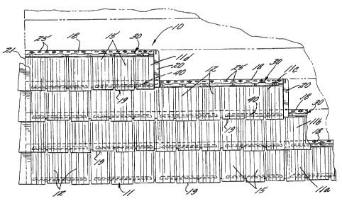
[0012] Figure 1 is a plan view of a wall covering comprising panels
constructed in
accordance with the present invention;
[0013] FIG. 2 is a front plan view of one of the panels of the wall covering
shown in FIG. 1.;
[0014] FIG. 3 is an enlarged front perspective of the panel shown in FIG. 2,
with a central
portion broken away;
[0015] FIGS. 4 and 5 are enlarged fragmentary sections of the illustrative
panel, taken in the
planes of lines 4-4 and 5-5, respectively in FIG. 3;
[0016] FIG. 6 is a rear plan view of the panel shown in FIG. 2;
[0017] FIG. 7 is an enlarged rear perspective of the panel shown in FIG. 6;
[0018] FIGS. 8 and 9 are enlarged fragmentary sections of the illustrated
panel taken in the
planes of lines 8-8 and 9-9, respectively in FIG. 7;
[0019] FIG. 10 is a partial plan view showing two installed courses of the
wall covering; and
[0020] FIGS. 11-13 are enlarged fragmentary sections taken in the planes of
lines 11-11, 12-
12 and 13-13, respectively.
[0021] While the invention is susceptible of various modifications and
alternative
constructions, a certain illustrative embodiment thereof has been shown in the
drawings and will
be described below in detail. It should be understood, however, that there is
no intention to limit
the invention to the specific form disclosed, but on the contrary, the
intention is to cover all
modifications, alternative constructions, and equivalents. The scope of the
claims should not be
limited by the preferred embodiments set forth in the examples, but should be
given the broadest
interpretation consistent with the description as a whole.
DETAILED DESCRIPTION OF THE INVENTION
[0022] Referring now more particularly to FIG. 1 of the drawings, there is
shown an
illustrative wall covering 10 comprising a plurality of plastic molded panels
11 in accordance
with the present invention. The general type of panel employed in the instant
invention is
CA 02607308 2012-05-11
4
described in commonly assigned U.S. Pat. Nos. 5,347,784 and 5,537,792. As
shown in FIG. 1,
the panels 11 each are formed with simulated building elements. In this
instance, the panels 11
are formed with simulated cedar shake shingles 12 of irregular width and
length which are
disposed in a single row substantially along the length of the panel.
[0023] The simulated shake shingles 12 in this case each have a front face 15
(FIG. 3)
extending downwardly and outwardly at a slight taper to a wall or support
surface 17 upon which
the panel is mounted, and the front face 15 is molded with grooves which
simulate the grain of
the simulated shake 12. It will be understood that the panels 11 could be
formed with other
forms of simulated shake shingles, or other types of building materials, such
as tile, brick and the
like.
[0024] Each panel 11 has an upper horizontal marginal edge region 18 having a
substantially
uniform width extending across the top of the panel immediately above the row
of shake 12, a
lower marginal edge region 19 adjacent an irregular lower peripheral edge of
the simulated
shake, a side marginal edge region 20 in the form of a laterally-extending
flange located to the
right-hand side of the last simulated shake 12 in the row, and a marginal edge
region 21 on the
opposite side of the panel 11 defined by a left-side peripheral edge
immediately adjacent the first
simulated shake shingle 12 of the row. The panels 11 are mounted on a support
surface 17,
which may be a wall or roof of a house or other building structure, in
horizontal courses with the
right-side marginal edge region 20 in underlying relation to the left-side
marginal edge region 21
of the panel immediately to the right thereof (as shown in FIG. 13) and with
the lower marginal
edge region 19 of the panels in each course overlying the upper marginal edge
region 18 of the
panel in the previously installed course immediately below. (see FIGS. 11-12)
[0025] The panels 11 typically are mounted beginning with the left-hand panel
of the
lowermost course to be installed on the wall or roof, as is known in the art.
Upon completion of
the first course, the second course is installed, immediately above the first
course, again starting
from the left-hand side. As is customary in the art, the left-hand marginal
edge region of the first
panel of each row may be appropriately cut square with the left side starting
edge of the support
surface. In the following description, when discussing the interaction of
panels disposed in
vertically displaced courses, the panels of the lower most course will be
designated with the
CA 02607308 2012-10-17
5
reference numeral "11 e and the panels of the subsequent courses will be
designated with the
reference numerals "11 b", "11c" etc. This convention is employed in order to
clarify the relative
positions and order of installation of the subject panels.
[0026] For securing the panels 11 to the support surface 17, the upper
marginal edge region
18 of each panel 11 is formed with a row of elongated laterally spaced nailing
apertures 25. In
order to provide firm support for the panel 11 on the wall during nailing and
for establishing a
seal between the rear side of the panel 11 and the support surface 17, the
upper marginal edge
region 18 in this instance is formed with rearwardly extending horizontal
sealing flanges 26
which surround the nailing apertures and extend substantially the length of
the upper marginal
edge region 18 (FIG. 7). Once the upper marginal edge region 18 is nailed to
the support surface,
the horizontal sealing flanges 26 are maintained against the support surface
17.
[0027] In accordance with the invention, the panels have an interlock
arrangement that
enables reliable inter-engagement of overlying lower and upper marginal edge
regions of the
panels upon upward positionable movement of the overlying panel during
installation and
which facilitates efficient handling of the overlying panel while being
secured to the support
surface. To this end, the panels 11 each have a continuous upper interlock
rail 30 that
extends substantially the length of the panel in forwardly and downwardly
directed relation
to the upper marginal edge region 18 of the panel that is engageable by a
lower upturned
interlock rail 40 of an overlying panel, which enables reliable inter-
engagement of the panels
without the risk of missing individual locking fingers, as in the prior art.
The illustrative
upper interlock rail 30 comprises a continuous downwardly directed interlock
flange 36 that
extends substantially the entire length of the panel, which is supported by a
plurality of
longitudinally-spaced horizontal support plates 32 integrally formed with the
upper marginal
edge region and reinforced by corner joints 35. The horizontal support plates
32 include a
lower surface 34 and in this case are located between the nailing apertures 25
and the upper
edge of the row building elements 12. The upper interlock flange 36 is
disposed a distance
from the forward surface of the upper marginal edge region 18 for defining a
locking flange
receiving slot 37, and a lower terminal end 38 of the locking flange is flared
outwardly for
guiding the bottom interlock rail 40 of an overlying panel into engaging
relation, as will
become apparent. To facilitate molding of the continuous interlock rail 30
with the panel 11,
the upper marginal edge region 18 in this instance is formed with a plurality
of laterally-
CA 02607308 2007-10-23
spaced generally rectangular openings 39 which allows tooling to protrude
forwardly through the 6
panel to form the locking flange 36. As will be understood by a person skilled
in the art, this
allows the upper interlock rail 30 to be integrally molded with the panel
without the necessity for
separate attachment, such as by welding.
[0028] The lower interlock rail 40, while also extending
substantially the length of the panel,
may comprise a single continuous rail or several relatively-long rail segments
40a as illustrated,
which in this case each extend the width of about three of the simulated shake
shingles 12. Each
lower interlock rail segment 40a includes an upturned interlock flange 42 that
is easily movable
into continuous engaging relation with the interlock flange 36 of the upper
rail 30. To facilitate
such inter-engagement, an upper terminal end 44 of the lower interlock flange
42 is rounded to
facilitate sliding, camming engagement with the downwardly-directed interlock
flange 36 of the
upper rail 30. It can be seen, therefore, that the interlock flanges 36, 42 of
the upper and lower
interlock rails 30, 40 can be easily moved into interlocking relation with
each other without
cumbersome manipulation of large numbers of small interlock fingers customary
of the prior art.
100291 In keeping with the invention, a cooperative detent
arrangement is provided for
further locating the interlock flanges 36, 42 in proper engaging relation to
each other and for
positively supporting the weight of the overlying panel for sufficient hang
time as to enable the
installer to secure the panel, such as by nailing or screwing, onto the
support surface without
manually supporting the weight of they overlying panel. To this end, a
rearward face of the
= bottom interlock flange 42 is formed with a protruding
detent 42a in the form of an elongated
rounded nib that extends horizontally the length of each rail segment 40a and
which is
positionable with snap action engagement into a corresponding rounded detent
recess 18a formed
in the upper marginal edge region of the underlying panel which extends
substantially the length
of the panel. It will be understood by a person skilled in the art that the
interlock flanges 36, 42
may be designed to forcefully urge the detents 42a, 18a into snap action inter-
engaging relation
with the each other as an incident to upward positioning of the overlying
panel during
installation. Since the detent ribs and recess 42a, 18a extend substantially
the entire length of the
panels sufficient frictional retention may be achieved to support the weight
of the panel for the
relatively short hang time necessary for enabling the installer to secure the
overlying panel in
mounted position. As used herein, the term "hang time means the time the
overlying panel will
CA 02607308 2007-10-23
7
remain supported by the inter-engaging detents to enable securement of the
panel to the support
surface without the need for manually supporting the weight of the panel.
[0030] While the detents 42a, 18a serve both to preliminarily locate the
overlying panel in
aligned relation to the underlying panel during installation and support the
panel during
securement of the panel in mounted position, the rounded configuration of the
detent nibs 42a
and recess 18a enable the panel to be selectively slid into and out of
engagement, such as may be
necessary in allowing the installer to adjust the final position of the
overlying panel. The
configuration of detents 42a, 18a further accommodates relative movement of
the panels from
temperature expansion and contraction of the panels during usage. While in the
illustrated
embodiment the detent ribs 42a are formed on the rear lower interlock flange
42 and the detent
recess 18a is formed on the front side in the upper marginal edge region 18 of
the underlying
panel, it will be understood that the reverse arrangement also could be used.
[0031] In further carrying out the invention, the interlock flange 42 of the
lower interlock rail
40 is supported across a rear side of the row of simulated shake building
elements 12 in a manner
that does not capture water that might migrate between the panels, which
facilitates air
circulation through the wall covering following installation, and which does
not detract from the
natural appearance of the simulated building elements and the installed wall
covering. In the
illustrated embodiment, the lower interlock flange 42 is supported by a
plurality of laterally-
spaced vertical support plates 48 that extent outwardly from the rear side of
the panel. The lower
interlock flange 42 in this case has an L-shaped configuration for added
structural rigidity, with a
base 46 of the L-shaped flange 42 being integrally formed with the vertical
support plates 48.
The vertical support plates 48 in turn define a plurality of apertures 49
between the rear side of
the panel and the interlock flange 42 which permit the free passage of any
water that might
migrate between the panels during severe weather conditions and which also
facilitates the
circulation of moisture laden air through the wall covering. Moreover, since
the lower interlock
flange 42 is supported entirely by the vertical plates 48, even if during
plastic injection molding a
faint line of the support plates 48 were visible from a front side of the
panel, it will blend into the
vertical graining of the simulated shake shingles 12 so as not to affect the
aesthetic appearance of
the installed wall covering.
CA 02607308 2007-10-23
8
[0032] It will be understood that the present invention has particular utility
with panels
which have a single row of simulated building elements, such as illustrated.
Since such panels
often are smaller and lighter in weight than panels which have a plurality of
rows of building
elements, smaller size detents may be utilized which are more readily
releasable during
adjustable positioning of an overlying panel during installation, as well as
from movement
during temperature expansion and contraction of the panels. With such single
course panels
being smaller in size, a multiplicity of panels also may be simultaneously
molded in
conventional sized molding equipment, with the panels having slightly
different shingle patterns
for providing a more varied and natural appearance of the finished wall
covering.
[0033] In keeping with this aspect of the invention, in the preferred
embodiment, the wall
covering is formed with the panels in one course being formed with slightly
different shingle
patterns than the panels in the vertically-adjacent row. In the wall covering
10 shown in FIG. 1,
for example, the panels 1 la and 1 1 c in the first and third courses may be
identically formed and
the panels 1 lb and lld may be identically formed with slightly different
characteristics of the
simulated shake than the panels 1 1 a and 1 1 c. Panels with such a single row
of simulated
building elements have the further advantage that, upon installation, the
individual rows the
building elements of each panel physically overlap each other, which further
enhances the
natural appearance of the wall covering. Less wastage also is incurred with
the use of panels
with single row simulated building elements because the cutoff section of the
panel that begins a
course may be used at the opposite end thereof. Nevertheless, it will be
understood that the
invention also is applicable to panels which include a plurality of rows of
simulated building
elements.
100341 From the foregoing, it can been seen that the roof and wall panels
according to the
invention have an interlock arrangement that is adapted for easier and more
reliable installation.
The continuous upper interlock rail facilitates substantially continuous
interlocking engagement
with a bottom interlock rail of an overlying panel without the cumbersome
handling of numerous
small interlock fingers which sometimes are missed during installation. The
cooperating detent
arrangement between the overlying lower and upper marginal edge regions of the
panels further
facilitates proper positioning of the overlying panel during installation, as
well as supporting the
weight of the panel sufficient to enable the installer to effect its
securement on the support
CA 02607308 2007-10-23
9
surface without cumbersome support of the weight of the panel. The bottom
interlock flange
further is supported transversely across a rear side of the row of simulated
building elements in a
manner which does not detract from the aesthetic appearance of the wall
covering and which
facilitates both liquid drainage and air circulation through the installed
wall covering.