Note: Descriptions are shown in the official language in which they were submitted.
CA 02607358 2007-10-19
~
Systesa for controlling flight direction
Field of the invention
The present invention relates to fixed wing aircrafts such as
s gliders and propeller driven airplanes and to flapping wing
aircrafts such as ornithopters. In particular it relates to
means and methods for controlling the flight direction of such
aircrafts.
Background of the invention
Typically, ailerons and an elevator control the flight
direction of airplanes. Ailerons are normally a part of the
trailing edge, the aft part of the wing, which is hinged so it
can tilt up and down. When the aileron is tilted down it alters
the shape of the wing and in effect increases the incidence
angle and.the angle of attack and thereby also the lift on that
wing. Wheri the aileron is tilted down on one wing it is always
tilted up on the opposite wing and thereby reducing the lift on
this wing.
The incidence angle is the angle between the cord line of the
wing and the longitudinal axis of the aircraft itself. The
angle of attack is on the other hand defined as the angle
between the cord line and the direction of the airflow. If we
change the incidence angle and keep everything else unchanged,
2s it can be appreciated that the angle of attack is changed by
the same amount. However, changing the attitude of the aircraft
by e.g. pulling the nose up, will change the angle of attack
while the,incidence angle remains unchanged.
CA 02607358 2007-10-19
2
The ailerons control the roll, the banking, of the airplane
while the elevator controls the pitch, the up-down direction of
flight. The elevator is typically placed at the trailing edge
of the stabilizer at the rear end of the airplane and by
tilting it up or down it alters the lift force on the
stabilizer and thereby controls the up and down direction.
To control the flight direction; the ailerons are used to bank
the airplane sideways and by applying a little up-elevator the
airplane performs a turn while it keeps its height in the air.
For a slow flying aircraft the ailerons can have less effect
and especially on single propeller airplanes it is possible to
instead use the rudder to control the flight direction. The
rudder is placed vertically at the tail of the airplane and
controls the yaw.
is Single propeller airplanes normally have the propeller placed
in the front, creating a fast airflow over the stabilizer,
elevator and rudder. Twin-engine airplanes, very slow flying
gliders or flapping wing aircrafts like ornithopters, however,
lack the-additional airflow over the stabilizers and rudder
that single propeller aircrafts normally have. For these kinds
of aircrafts it can be more difficult to get a good directional
control.
One way of overcoming this problem is in the case of a twin-
engine airplane to use differential thrust. Each of the two
motors, jet engines or propellers which typically are placed
one on each wing, can be controlled individually. By increasing
the speed of one motor and reducing the speed of the opposite
motor the flight direction can be controlled. This is a well-
known way of controlling a twin-engine airplane and it is
described in e.g. US patent US6612893.
In the case of ornithopters the forward thrust is produced by
the flapping wings and not by propellers. If the ornithopter in
CA 02607358 2007-10-19
3
addition flies slowly, a normal rudder at the back of the
aircraft has reduced effect. One way of trying to solve this
problem is to make the whole tail movable. This solution is
shown in e.g. US patent US6550716. Here the whole tail is
hinged and controlled by servos. This solution is believed to
be both fragile and complicated.
A simpler way of controlling slow flying small aircrafts, like
remotely controlled toy airplanes or slow flying ornithopters
is to use a small vertically placed propeller instead of the
rudder at the rear end of the aircraft. This method is
described in US patent application US 20040169485. The small
propeller can blow air to either left or right and thereby
pushes the tail sideways to control the flight direction.
However, when the aircraft turns e.g. to the left it normally
also banks or rolls over to the left. In this position the tail
is pushed up by the blowing tail propeller and the effect of
this is almost like having a down-elevator action forcing the
aircraft into a downwardly turn instead of a gentle turn where
the height is kept. This tendency makes it more difficult to
perform tight maneuvers with this system.
Especially for slowly flying aircraft with high angles of
attack and for flapping wing aircrafts the existing systems
have limitations. Some of the ways for controlling the flight
direction described above are both innovative and simple but it
is believed that an even simpler and better system is possible.
Surnmary of the invention
The present invention aims at fulfilling the need for a very
simple and low cost way of controlling the flight direction of
an aircraft flying slowly or with a high angle of attack by
changing the incidence angles of its wings. Furthermore such
CA 02607358 2007-10-19
4
control means could be used to control a slow flying flapping
wing aircraft.
A control means that receives a control signal indicating a
left turn increases the incidence angle and thereby also the
angle of attack on the left wing and reduces it on the right
wing. For a right turn the opposite action is performed. An
aircraft that utilizes the current invention for directional
control will benefit from having airfoils (e.g. flat plates)
that experiences increased drag as the angle of attack
increases but have a generally constant lift at high and
increasing angles of attack.
Normally an aircraft depends on changes in the lift on its
wings to control the flight direction. The current invention,
however, is able to'manoeuvre mainly due to drag differences on
the wings. To perform controlled manoeuvres the wings incidence
angles are changed in the opposite direction of what is normal
on all other airplanes.
Finally different means for controlling the incidence angles
and thereby the angles of attack on fixed and flapping wings
according to the present invention are briefly discussed.
Brief description of the drawings
The following detailed description of the preferred embodiment
is accompanied by drawings in order to make it more readily
understandable. In the drawings:
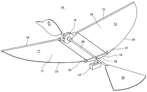
Figure 1 is a perspective view of a flapping wing aircraft with
a teetering control means for changing the incidence angle of
the wings.
CA 02607358 2007-10-19
Figure 2a and 2b is rear views of the aircraft in Figure 1
showing the control means in a neutral position and in a right-
turning position.
Figure 3 is a perspective view of the aircraft in Figure 1
5 turning to the left.
Figure 4 is a perspective view of a control device comprising
gears and a motor.
Figure 5 is a perspective view of a control device comprising a
permanent magnet and a U-shaped electro magnet.
io Figure 6 is a perspective view of a control device comprising a
link arm, a permanent magnet and an electro magnetic coil.
Figure 7 is a perspective view of a control device comprising
an arm pivoting around a wing spar, a link arm and a servo.
Figure 8a and 8b are perspective views of an aircraft; the
incidence angles are shown in a neutral and in a turning
situation.
Figure 9 is a diagram showing drag coefficients (Cd) and lift
coefficients (Cl) for a flat plate airfoil.
Detailed description of the preferred embodiment
In the following the present invention will be discussed and
the preferred embodiment described by referring to the
accompanying drawings. Alternative embodiments will also be
discussed', however, people skilled in the art will realize
other applications and modifications within the scope of the
invention as defined in the enclosed independent claims.
CA 02607358 2007-10-19
6
In figure 1 the preferred embodiment of an aircraft (10)
according to the present invention is shown. It is a flapping
wing aircraft, an ornithopter, utilizing a control means to
control the flight direction. The present invention aims at
fulfilling the need for a very simple, low cost and effective
way of controlling the flight direction of an aircraft flying
slowly or with a high angle of attack.
Normally an aircraft depends on changes in the lift on its
wings to control the flight direction. Utilizing the current
invention it is, however, possible to manoeuvre mainly based on
drag differences between the left and right wings. To perform
controlled rrianoeuvres the wings' incidence angles are changed,
but they are changed in the opposite direction of what is
normally seen on all other airplanes. How this is possible is
described in detail later.
For the sake of this description and as used in the claims,
lift is a force acting perpendicular to the direction of flight
sustaining the aircraft in the air. Lift can be generated by
the wingsor by the thrust from a propeller/rotor having a
vertical force component. Drag on the other hand, is a force
acting in the opposite direction of flight, slowing down the
aircraft. A major part of the drag acts upon the wings.
For clarity, the ornithopter (10) is shown as a principal
sketch and all electronics, power sources and control wires, as
well as the body of the ornithopter are not shown. The
ornithopter (10) has an internal frame or a rod (26) going from
the head back to the generally horizontal tail (25). The rod
(26) is parallel to the longitudinal axis of the aircraft and
it holds the flapping mechanism (16), which is positioned just
behind the head of the ornithopter.
The ornithopter (10) is a radio controlled electric flying toy
and in addition to what is shown and described, there will also
be batteries, control electronics including driving circuits
CA 02607358 2007-10-19
7
and an electric motor for powering the flapping mechanism (16).
Rods (14,15) are mounted to the flapping mechanism (16) to
create the wing spars and leading edges of the wings (11,12).
One rod (14) is extending out to the left, perpendicular to the
internal f'rame (26) and the other rod (15) is extending out to
the right. They are both mounted to the flapping mechanism (16)
with a nominal angle in the vertical plane to give the wings a
dihedral for'better stability. The result of this is that when
the flapping mechanism (16) moves the tip of the wings (11,12)
up and down they will have its lower position just below the
horizontal plane while the upper position is close to a 45
degrees angle.
The major part of the wings (11,12) is made of a thin flexible
material (17,18). The flexible material (17,18) is cut out to
give the wings (11,12) a tapered shape with a straight leading
edge and a curved trailing edge (23,24). The cord lines of the
wings are longest in the inner end, closest to the centre line.
Along its leading edge the flexible material (17,18) is
attached to,the straight rods (14,15) that are mounted to the
flapping mechanism (16).
To control the ornithopter (10) the inner end of the wings
(11,12) are at a point close to their trailing edges (23,24)
connected to a control means. The control means comprises a
force-transmitting member, a generally horizontal rocker arm
(19), that is pivotally connected (22) to the internal frame
(26), enabling the arm (19) to tilt up and down, teeter, about
the pivot. point (22). At each end of the rocker arm (19) there
are connecting points (20,21) where the wings are connected to
the rocker arm. From the midpoint of the rocker arm (19) a
vertical member is extending down into the lower part of the
control means. In the lower part of the control means an
actuator.(13) is used to move the vertical member from side to
side. This movement generated in the lower part of the control
means causes the rocker arm (19) to teeter and thereby can e.g.
the left connecting point (20) be moved down while the right
CA 02607358 2007-10-19
8
connecting point (21) is moved up. Since the wings (11,12) are
flexible mounted (via the flexible wing material) to the rods
at the leading edge and since they are connected to the
connecting points (20,21) their average incidence angles (and
therefore also their average angles of attack) will be changed
as the rocker arm (19) teeters. The direction and force of the
movements are linked to an input, a control signal (not shown),
driving or setting the actuator (13) in the correct position.
Different technical solutions for the control means, the
io actuator and the force-transmitting member are shown in figure
4 to 7 and are described later.
Figure 2 and 3 show how the actuator (13) and the rocker arm
(19) change the average incidence angles of the wings on the
ornithopter (10) to control the direction of flight. In figure
2a the rocker arm (19) is horizontal and both wings have the
same incidence angle. The ornithopter is flying straight
forward. In figure 2b, however, the rocker arm (19) is tilted
to the right. Now the left connecting point (20) is moved up
and the right connecting point (21) is moved down. Since the
wings are connected to these points (20,21) we can appreciate
that the trailing edge (23) of the left wing will be moved up
causing the incidence angle and the angle of attack on the left
wing (11).to be reduced wile the trailing edge (24) of the
right wing (12) will be moved down and thereby increasing the
incidence angle and the angle of attack on the right wing (12).
This causesthe ornithopter to turn to the right. Figure 3
shows the opposite situation with the trailing edge (23) of the
left wing.moved down and the trailing edge (24) of the right
wing moved up. Now the ornithopter (10) turns to the left.
It is important to notice that the changes in incidence angles
used to control aircrafts according to the present invention is
the opposite of what is normally used to control the flight
direction on aircrafts that fly faster or with lower angles of
attack. It is drag-differences due to changed angles of attack
CA 02607358 2007-10-19
= 9
and not lift-differences that initiate a change in the flight
direction. This is the main feature of the present invention.
Furthermore this way of controlling an aircraft can be used for
ornithopters with flapping wings as well as for gliders and
s other slow flying aircrafts. Because the wings of a flapping
wing airctaft are flexible the incidence angles will vary over
the wingspan and during the wing-strokes. The drag and lift
acting on such wings are mainly linked to the average angle of
attack over the wing. The aircraft shown in figure 8a and 8b
io have rigid wings and airfoils like thin plates. The wings are
pivotable mounted to the rest of the aircraft. When these wings
rotate about their pivoting axis (not shown) their respective
incidence angles changes (Al to A2, Bl to B2). When the
incidence angles are changed the angles of attack are also
is changed in the same direction.
It will be appreciated that this control principle also
functionsif only parts of the wings have changing incidence
angles. The same result can be achieved if the wings consist of
e.g. two parts, a rigid part mounted to the aircraft and a
20 moving part pivotable connected to the rigid part. When the
angle of the movable part is altered the average incidence
angle (and angle of attack) on the whole wing will be changed.
All aircrafts experience an effect called adverse yaw when they
use their ailerons to initiate a turn. To turn to the right the
25 aileron on the left wing is moved down, locally increasing the
average angle of attack on the left wing while the aileron on
the right wing is moved up, locally reducing the average angle
of attack on the right wing. On an ordinary airplane having
normal airfoils these changes in the incidence angles causes
30 the lift on the left wing to increase significantly and the
lift on the right wing to be reduced. This difference in lift
initiates a.right turn. However, another effect is also
present: The increased average angle of attack on the left wing
causes the drag on that wing to increase while the drag on the
CA 02607358 2007-10-19
= 10
right wing is reduced. This difference in drag force acting on
the wings tries to yaw the aircraft to the left while it banks
to the right. This effect is called adverse yaw. On all
aircrafts this is a totally unwanted effect and must be
s compensated for by the use of the rudder or by other means
trying to reduce the drag differences.
To describe how the present invention is used to control the
flight direction we can turn to figure 8 and 9. If we can
utilize the increased drag on the wing that gets an increased
io angle of attack without also substantially increasing the lift,
we could control the direction of flight. In figure 8a and 8b
an airplane with flat plate wings is shown. If we also look at
the diagram in figure 9 showing typical graphs for lift and
drag coefficients for a cross-section of a flat plate as a
15 function of angle of attack, we can see that these wings does
not stall like ordinary wings with proper airfoils. The lift
coefficient (Cl) increases as the angle of attack increases
from zero. and up, however, we do not see a sudden and
significant drop in the lift (stall) as the angle of attack
zo continuesto increase. Instead, when the angle of attack is
high enough we can continue to change the angle of attack
without substantially altering the lift.
An airfoil can be defined as the shape of a wing as seen in
cross-section. Many shapes, such as a flat plate set at an
25 angle to the flow, will produce lift. However, lift generated
by most shapes will be very inefficient and create a great deal
of drag. One of the primary goals of airfoil design is to
devise a shape that produces the most lift while producing the
least drag. For almost all airfoils the graphs for section lift
30 coefficient vs. angle of attack follow the same general shape,
but the particular numbers will vary. The graphs shows an
almost linear increase in lift coefficient with increasing
angle of attack, up to a maximum point, after which the lift
coefficient falls away rapidly. The airfoil is now in stall. In
35 aerodynamics, a stall is a sudden reduction in the lift forces
CA 02607358 2007-10-19
= 11
generated by an airfoil and occurs when a "critical angle of
attack", the stall angle, for the airfoil is exceeded.
Stalling is an unwanted effect, but during normal flight in an
ordinary airplane it causes no immediate problems. Normally the
s airfoil of the wing has an angle of attack well below the stall
angle. The positive effects the airfoil has on lift and drag
efficiency more than outweighs the stall behavior.
In the present invention, however, we need wings and airfoils
that do not show a typical stall behavior. For the sake of this
io description and as used in the independent claims a "lift-
preserving airfoil" is defined. A wing employing such lift-
preserving airfoils is characterized by:
- Lift that increases as the angle of attack increases from
zero, and up, without having a sudden and significant drop
is in the lift as the angle of attack continues to increase.
- At high angles of attack, a continued increase in the
angle of attack will not substantially alter the lift.
- Drag that increases continuously as the angle of attack
increases from zero and up.
20 Examples of such lift-preserving airfoils are flat plates, very
thin airfoils with a sharp leading edge, special airfoils with
a large atep or hole in the top surface. These airfoils are
normally not used in any aircrafts because their lift and drag
efficiency is not very good, however, they may be used in the
25 wings of an aircraft utilizing the present invention to control
the flight direction.
Another example on lift-preserving airfoils is the thin and
flexible'airfoil typically used in some flapping wing
aircrafts,, including the airfoil described in the preferred
30 embodiment of the present invention. It is believed that the
flexibility of such airfoils and the fact that they change in
shape during the wing strokes contributes to suppressing stall
CA 02607358 2007-10-19
12
and allows the angle of attack to be increased without
experiencing a significant drop in the lift.
If we have an aircraft, a fixed wing glider or an ornithopter
with such.lift-preserving airfoils (and where the lift
generated by these airfoils contributes a major part of a total
vertical force needed to sustain flight, as opposed to an
aircraft hanging by the thrust from its propeller), we can
appreciate that when we fly at an angle of attack close to or
in the region where the lift is not substantially increasing, a
further increase in the angle of attack on one of the wings
will not lead to a substantially increase in the lift on that
wing. If the lift had increased, this would have caused the
aircraft to bank and initiate a turn in the opposite direction
of what we intended.
is When we then look at the drag, we will see that it increases
continuously as the angle of attack increases.. Since the
incidence angle and the angle of attack is closely linked we
can now appreciate that the airplane in figure Bb will, since
it flies with a high angle of attack, have about the same lift
on both wings even if the incidence angle (A2) on the left wing
is larger.than the incidence angle (B2) on the right wing. The
drag will; however, be higher on the left wing than on the
right wing and the aircraft will turn to the left - completely
opposite of what one would normally expect.
There are several other factor influencing on the aircrafts
described in the present invention but the differences in drag
is believed to be the most important factor enabling this new
way of controlling the flight direction.
For anyone skilled in the art it will be obvious that an
aircraft, fixed wing or flapping wing, equipped with more than
one set of wings also can benefit from utilizing the present
invention to control the flight direction. E.g. and ornithopter
with two left wings and two right wings, the wings within each
CA 02607358 2007-10-19
13
pair flapping in opposite direction, may very well have a
control device for adjusting the incidence angles of the wings
in order to control the direction of flight. On the other hand,
changing the incidence angle on only one wing on an aircraft
having one or more additional fixed wings could also be used to
control the flight direction.
In figures 4, 5, 6 and 7 different devices for changing the
incidence angles are shown.
In figure 4, the preferred embodiment of the present invention
(40), utilizing a motor actuator and gears is shown. A force-
transmitting member, a generally horizontal rocker arm, (41) is
pivotally connected (42) to a shaft enabling the arm (41) to
tilt up and down, teeter about the shaft. At each end of the
arm (41) there is a connecting point (43,44) used to mount or
connect the inner aft part of the wings to the rocker arm (41).
From the midpoint of the rocker arm (41) a vertical arm (45) is
extending down ending in a gear segment (46). An actuator in
the form of a motor (47) with a small gear (48) is placed below
the gear segment (46) and is acting together with the gear
segment (46) so that when the motor (47) rotates, the rocker
arm (41) teeters and thereby can e.g. the left connecting point
(43) be moved down while the right connecting point (44) is
moved up.'Since the wings are connected to the connecting
points (43,44) their incidence angles will be changed in
opposite directions as the rocker arm (41) teeters. The motor
(47) will rUn just a few turns in each direction, depending on
the gear.ratio. The direction and force of the movements are
linked to an input signal (not shown) driving the motor.
If the vertical arm (45) was positioned off centre or had a
different shape, the gear segment (46) could be placed below
the small gear (48) with the teeth facing upwards. This is a
somewhat more complicated design but it has the advantage that
the gear ratio will be higher enabling a higher force to be
transmitted trough the rocker arm (41).
CA 02607358 2007-10-19
= 14
In figure 5, a control device (50) utilizing a U-shaped electro
magnet actuator is shown. A generally horizontal rocker arm
(51) is pivotally connected (52) to a shaft enabling the arm
(51) to tilt.up and down, teeter about the shaft. At each end
of the arm (51) there is a connecting point (53,54) used to
mount or connect the inner aft part of the wings to the rocker
arm (51). From the midpoint of the rocker arm (51) a vertical
arm (55) is extending down ending in a permanent magnet (56).
An U-shaped electro magnet (59) with left (57) and right (58)
iron poles is placed below the permanent magnet (56) and is
acting together with the permanent magnet (56) so that when the
electro magnet (59) is activated the permanent magnet (56) and
the arm (55) is pulled against e.g. the left pole (57). This
teeters the rocker arm (51) and thereby can the incidence
angles of the wings be controlled in the same way as described
above for the motor actuator (40). The direction and force of
the movements are linked to an input signal (not shown) driving
the electro magnet (59).
In figure-6, a control device (60) with an actuator utilizing a
circular coil magnet is shown. A generally horizontal rocker
arm (61) is pivotally connected (62) to a shaft enabling the
arm (61) to tilt up and down, teeter about the shaft. At each
end of the arm (61) there is a connecting point (63,64) used to
mount or connect the inner aft part of the wings to the rocker
arm (61)..From the midpoint of the rocker arm (61) a vertical
arm (65) is extending down and at the end it is equipped with a
hole (66). A generally horizontal member, a link arm, (67) is
mounted in the hole (66) and extends out to the left where it
is connected to a permanent magnet (68). The permanent magnet
(68) is positioned inside a circular coil and together with the
link arm (67) it is free to move sideways. When the coil (69)
is activated the permanent magnet (68), the link arm (67) and
the vertical arm (65) is pulled to e.g. the left. This teeters
the rocker arm (61) and thereby can the incidence angles of the
wings be controlled in the same way as described above (40).
CA 02607358 2007-10-19
The direction and force of the movements are linked to a input
signal (not shown) driving the coil (69).
Other kinds of electronic actuators can be adapted to control
the incidence angle of a wing_ A piezoelectric actuator can
5 very well replace the magnetic coil (69) and magnet (68) in the
embodiments shown in figure 6. Another alternative is to use
piezoelectric material in the rocker arm (61) itself. The inner
parts of the arm can be replaces with a piezoelectric element,
while the outer parts of the arm have the original connecting
io points (63,64) and transmit the force to the wings. The pivot
point (62) is not used and the rocker arm is in stead fixed to
the aircraft. When the piezoelectric material bends in response
to an electric input the outer parts of the arm and the
connecting points (63,64) acts as force-transmitting members
15 moving the wing up or down.
In figure 7, a control device (70) utilizing a servo is shown.
A generally horizontal force-transmitting arm (71) is
positioned in the longitudinal direction of the aircraft. At
its foremost point it is pivotally connected (72) to a shaft
enabling the aft part of the arm (71) to tilt up and down. At
the aft end of the arm (71) there is a connecting point (73)
used to mount or connect the inner aft part of one wing to the
arm (71). A hole (76) is placed on the arm (71). A second
force-transmitting member, a vertical link arm (77), is mounted
in the hole (76) and is extending down. At the lower end, the
link arm (77) is connected to a servo arm (75) on a servo (78).
When the servo arm (75) is moving it causes the arm (71) and
the connecting point (73) to move up or down and thereby can
the incidence angle of one of the wings be controlled. The
direction and force of the movement is linked to an input
signal (not shown) driving the servo (78). One control device
(70) changes the incidence angle of only one wing. With a
minimum of adjustments this control means (70) can be an
integrated part of a flapping wing so that the trailing edge of
CA 02607358 2007-10-19
16
the wing does not need to be directly connected to the body of
the aircraft.
Another alternative use of the embodiment shown in figure 7 is
in case of a fixed wing aircraft. In this embodiment the
connecting point (73) will not be used, but in stead the arm
(71) is directly connected to the wing itself or it can be an
integrated part of the wing. When the force from the servo is
transmitted to the wing via the vertical link arm (77) the wing
is moved iqp or down causing the incidence angle of the
otherwise fixed wing to be changed. It will be obvious to
anyone skilled in the art that the same system can also be used
to control the angle of only a part of the wing, this part
being pivotable connected to the rest of the wing.
Figure 7 can furthermore be used to illustrate how the flight
direction, or more correctly the rate and direction of a turn,
can be manually set before the flight starts. If the servo (78)
acts like a friction element, a retaining or holding force is
transmitted via the vertical link arm (77) to the arm (71)
holding it in one position as long as there is no manual input.
The input.controlling the incidence angle will now be a manual
force, setting or adjusting the position of the arm and thereby
also the incidence angle of the wing. The arm (71) holds the
wing in position when there is no input and moves the inner
part of the wing up or down in response to a manual force
applied to its aft most end. The friction in the servo (78) is
large enough to hold the arm (71) in position during flight but
low enough to be overcome by a manual input.
If the actuator (motor) in figure 4 was a mechanical friction
element acting against the teeth in the lower part of the
rocker azm this embodiment could also function as a manual
input device. By manually tilting the rocker arm, the new turn
rate can be set. The motor could also very well be replaced by
a pointed spring member resting between the teeth, allowing for
a stepwise adjustment of the rocker arm position. If the rocker
CA 02607358 2007-10-19
17
arm is equipped with a vertical member extending up over the
wings, this member can be used as a finger grip for easy manual
adjustments.
While the,preferred embodiment of the present invention have
been described and certain alternatives suggested, it will be
recognized by people skilled in the art that other changes may
be made to the embodiments of the invention without departing
from the broad, inventive concepts thereof. It should be
understood, therefore, that the invention is not limited to the
io particular embodiments disclosed but covers any modifications
which are within the scope and spirit of the invention as
defined in the enclosed independent claims.