Note: Descriptions are shown in the official language in which they were submitted.
CA 02607516 2008-10-22
1
INTRAVASCULAR DELIVERABLE STENT FOR
REINFORCEMENT OF VASCULAR ABNORMALITIES
FIELD OF THE INVENTION
This invention relates generally to an intravascular deliverable stent or
graft.
In particular this invention relates to a unique stent or graft for the
treatment of
aneurysms, lesions, and saphenous vein grafts by reinforcing, excluding,
bridging, or
lining a blood vessel. Although emphasis is given to such a stent or graft
specifically
designed for addressing aneurysms and particularly iliac artery and abdominal
aortic
aneurysm (AAA), other embodiments suitable for saphenous vein graft (SVG),
dialysis graft, and carotid arteries are also disclosed.
BACKGROUND OF THE INVENTION
An aortic aneurysm is a weak area in the aorta, the main blood vessel that
carries blood from the heart to the rest of the body. The aorta extends
upwards from
the heart in the chest and then arches downwards, traveling through the chest
(the
thoracic aorta) and into the abdomen (the abdominal aorta). The normal
diameter of
the abdominal aorta is about one inch (25mm). As blood flows through the
aorta, the
weak area bulges like a balloon and can burst if the balloon gets too big.
Most commonly, aortic aneurysms occur in the portion of the vessel below the
renal artery origins. The aneurysm may extend into the vessel's supplying the
hips and
pelvis, including the iliac arteries.
Once an aneurysm reaches 5 cm (about 2 in.) in diameter, it is usually
considered necessary to treat to prevent rupture. Below 5 cm, the risk of the
aneurysm
CA 02607516 2007-10-24
2
rupturing is lower than the risk of conventional surgery in patients with
nonnal
surgical risks. The goal of therapy for aneurysms is to prevent them from
rupturing.
Once an AAA has ruptured, the chances of survival are low, with 80-90 percent
of all
ruptured aneurysms resulting in death. These deaths can be avoided if the
aneurysm is
detected and treated before it ruptures and ideally treated at an early stage
(smaller
aneurysm) with a lower risk procedure.
Most aortic aneurysms occur in the abdominal aorta, the main cause being
arteriosclerosis. This is a condition in which fatty deposits are laid down in
the walls
of the arteries, which are less elastic and weaker as a result. Major risk
factors for
arteriosclerosis are smoking and high blood pressure as well as genetic
factors.
AAA can be diagnosed from their symptoms when they occur, but this is often
too late. They are usually found on routine physical examination and chest and
abdominal X-rays. On examination, a doctor may feel a pulsating mass in the
abdomen. If the doctor suspects an aneurysm, he/she will probably request that
an
ultrasound scan be carried out. Other scans, such as computerized tomography
(CT)
and magnetic resonance imaging (MRI) may also be performed. These scanning
techniques are very useful for determining the exact position of the aneurysm.
The surgical procedure for treating AAA involves replacing the affected
portion of the aorta with a synthetic graft, usually comprising a tube made
out of an
elastic material with properties very similar to that of a normal, healthy
aorta. This
major operation is usually quite successful with a mortality of between 2 and
5
percent. Even during surgery, the risk of death from a ruptured AAA is about
50%.
More recently, instead of performing open surgery in undertaking aneurysm
repair, vascular surgeons have installed an endovascular stent/graft delivered
to the
site of the aneurysm using elongated catheters that are threaded through the
patient's
blood vessels. Typically, the surgeon will make a small incision in the
patient's groin
area and then insert a delivery catheter containing a collapsed, self-
expanding or
balloon-expandable stent/graft to a location bridging the aneurysm, at which
point the
stent/graft is delivered out from the distal end of the delivery catheter and
allowed or
made to expand to approximately the normal diameter of the aorta at that
location.
CA 02607516 2007-10-24
3
The stent/graft, of course, is a tubular structure allowing blood flow through
the
lumen thereof and removing pressure from the aneurysm. Over time, the
stent/graft
becomes endothelialized and the space between the outer wall of the stent and
the
aneurysm ultimate fills with clotted blood. At this time, the aneurysm is no
longer
subjected to aortic pressures and thus will not continue to grow.
In treating AAA, it is important that the stent or graft be accurately placed
so
as not to occlude blood flow through the renal arteries which branch off from
the
abdominal aorta.
In the Amplatz et al. U.S. Patent No. 6,932,837, there is described a
collapsible stent/graft designed for grafting a lumen of a selected blood
vessel or other
tubular organ. The stent/graft comprises a woven or braided fabric made from a
plurality of strands of a shape memory alloy. The fabric is formed as a tube
and each
end of the device is open to allow fluid flow therethrough. The device can be
longitudinally stretched to thereby reduce its diameter, allowing it to be
inserted
within the lumen of a delivery catheter. When ejected from the distal end of
the
delivery catheter, the stent/graft will self-expand to a predetermined outer
diameter
sufficient to engage the wall of the tubular vessel being treated.
While the device in the'837 patent is altogether suitable for use as a
coronary
stent, it is not well suited for the intravascular treatment of AAA. That
device is of a
uniform weave, but necessarily is of a wire density that is insufficient to
limit the
exposure of the aneurysm to aortic blood pressure. Should this stent/graft
also
encroach upon the ostia of the renal arteries, it could restrict blood flow to
the
kidneys.
A need, therefore, exists for a stent/graft that can be placed using an
endovascular approach in the treatment of AAA, but that will not unduly
occlude
blood flow to the kidneys. The present invention provides such a device.
Aneurysms may also occur in the thoracic aorta where the renal arteries are
not
involved in the procedure, or in other arteries in the body. Depending on
where the
aneurysm is in relation to other branch vessels, different design variations
may be
needed. In some cases, where no branch vessels are involved, the stent/ graft
wall
CA 02607516 2007-10-24
4
may be uniform throughout. In cases involving the upper aorta, one portion of
the
stent/ graft, either the proximal, distal or area in between, may need to have
a portion
of the stent/graft wall with larger openings to allow adequate flow to the
carotid
arteries as compared to the balance of the stent/graft where the wall may have
much
smaller openings.
Regardless of the aneurysm site being treated, there is a need for an improved
stent or vascular graft that can be collapsed to a very small deliverable
diameter to
reduce the arterial puncture access sheath size, trauma to the vessel at the
access site
and to provide for a smaller, more trackable delivery system that is less
traumatic to
the vasculature. There is also a need for a low profile stent or graft that
provides
vascular support, exclusion of aneurysms, and a surface for rapid
endothelialization.
The invention herein provides such benefits.
In the field of interventional cardiology, it is now becoming routine to treat
stenotic lesions, in the vascular system, including saphenous vein grafts and
carotid
arteries, using balloon angioplasty to render more patent a partially occluded
blood
vessel and to attempt to thwart restenosis by placement of a stent at the site
of the
treated lesion.
Stents used in these procedures must be capable of assuming a reduced
diameter configuration for delivery through a guide catheter or arterial
sheath, but
which is either self-expanding upon exit of the distal end of the guide
catheter or
"balloon expandable".
In carrying out a balloon angioplasty procedure with stenting, the Seldinger
technique is frequently used to gain access to the vascular system and a
tubular
introducer having a hemostatic valve for preventing blood loss is inserted
through the
puncture wound from the skin into the artery. In order to perform the
procedure via
percutaneous access without surgical cut down to expose the femoral artery, an
introducer sheath smaller than 14 Fr (typically 6-8 Fr) is required in most
patients.
The smaller the introducer sheath, the less trauma to the tissue and the
easier it is to
place and to close the arterial puncture after the procedure. In some cases a
long
arterial sheath substitutes for a short vascular access sheath and provides a
guiding
CA 02607516 2007-10-24
path for delivery of devices to a site proximal the target treatment location.
In other
cases, a guide catheter is inserted through the introducer sheath and routed
through the
vascular system until the distal end portion of the guide catheter is disposed
at the
ostium of a selected artery having the stenotic lesion. Recently, steerable
sheaths have
5 been available for difficult to reach locations where sharp bends are
encountered.
Next, a catheter may be advanced over a guide wire through the sheath or
guide catheter, through the artery to the target treatment site. The catheter
may be a
balloon catheter, with or without a balloon expandable stent mounted over the
balloon, or may be a delivery catheter for a self expanding stent. Treatment
typically
involves dilation of the stenotic lesion, followed by placement of a stent at
the lesion
site. Upon inflation of the balloon, the stenotic region of the artery having
a
restriction to flow is expanded in diameter to restore normal blood flow
through the
arterial segment. A balloon expandable or self expanding stent may next be
placed in
the dilated lesion site to maintain the vessel wall in the expanded diameter
state.
Balloon expandable stents are placed by inflating a balloon having a stent
mounted
thereon at the lesion site. Self expanding stents are typically placed by
pulling back a
sheath covering a compressed stent mounted at the distal end of the catheter.
Following self expansion of the stent a balloon dilatation may optionally be
used to
seat the stent and ensure full expansion. Following the treatment, the
catheter, guide
wire, sheath, etc. are removed from the body and the vascular access site
sealed by
compression or other sealing means available.
Stents intended for use in percutaneous transluminal angioplasty applications
come in various lengths and diameters to generally approximate the lesion
length and
normal range of vessel inside diameters at the various treatment sites
throughout the
body.
Saphenous vein graft (SVG) treatment, following a previous coronary by-pass
procedure, often occurs after aging grafts become diseased and filled with a
soft
grumous material that can easily embolize during stenting or angioplasty. Such
emboli can cause obstructions in the coronary arteries downstream to which the
grafts
are connected.
CA 02607516 2007-10-24
6
There is a need for a stent or graft that can be delivered in a very low
profile in
the collapsed state and that can line the SVG, providing vessel support, as
well as
preventing emboli from the SVG wall from reaching the coronary arteries.
Another recent treatment of lesions involves the carotid arteries and, in
particular, treating the lesions with self expanding stents following balloon
angioplasty. Since these arteries, internal carotids, lead to the brain and
such lesions
often contain friable plaque that can break off and cause strokes, it is
necessary to
deploy a distal filter or other proximal occlusion / extraction means, during
the
procedure to prevent emboli from reaching the brain during the procedure.
Although
this protection means helps to prevent emboli during the procedure, the stent
itself
does not provide adequate protection for preventing emboli after the stent
deployment
procedure due to the large open areas in the stent at the vascular wall
surface.
There is a need for a stent for the carotid arteries that provides adequate
vascular support as well as provides protection from emboli, and therefore
stroke
prevention, after the procedure is completed and the procedural protection
systems are
no longer in place.
In attempts to anchor prior art stents against unwanted migration following
implant, vessel wall-engageable hooks are believed to cause damage to the
endothelium and the situs of stenotic lesions. Thus, a need also exists for a
stent or
grant that is self-anchoring without requiring tissue penetrating hooks.
SUMMARY OF THE INVENTION
The present invention provides a catheter-deliverable, endovascular
stent/graft
for treating vascular abnormalities, such as AAA, aneurysms in the thoracic
aorta or
other locations, SVGs and lesions, particularly in the carotid arteries that
comprises an
innermost tubular structure having a first length surrounded by at least one
further
tubular structure with a second length and means for connecting the structures
together and whereby at least one of the innermost or further tubular
structure(s)
provides substantially more "radial support" to the stent/graft than the other
structure.
CA 02607516 2007-10-24
7
The innermost tubular structure comprises a plurality of braided wire strands
exhibiting highly elastic characteristics, preferably a shape memory alloy. If
the
innermost structure is chosen as the primary radial support member of the
stent/graft,
the pick and pitch of the braid are chosen to defme openings sufficiently
large so as to
not materially impede blood flow through the wall of the innermost tubular
structure.
The at least one further tubular structure also comprises a plurality of
braided wire
strands. If the further tubular structure(s) is not the primary radial support
member of
the stent/graft, the wire strands of the further braided tubular structure
also comprise a
shape memory alloy and the braid has a pick and pitch which define openings
sufficiently small so as to substantially preclude blood flow therethrough.
The wire diameter of the primary radial support member is chosen to provide
the primary radial support to the arterial wall to anchor the stent/graft
while also being
sufficient to exert radial force to the adjoining connected tubular
structure(s) to urge
the structures against each other and against the vessel wall.
The diameters of the wires of the non-primary support structure(s) are smaller
and in greater quantity than the diameter and number of wires that comprise
the radial
support member. The radial expansion force is sufficient to self-expand the
structure.
Because the stent/graft of the present invention is designed to expand to a
diameter
greater than that of the vessel at the treatment site and because of the tiny
fenestrations
present, rapid endothelialization takes place. Thus, the need for anchoring
hooks as in
prior art stent/grants is obviated.
It is contemplated that the radial support structure of the stent may be the
innermost tubular structure, a middle further tubular structure or an
outermost further
tubular structure, as desired, for a particular use. The radial support member
has
fewer, but larger diameter wires with braided openings which do not inhibit
blood
flow through the braid, compared to the non-radial support member which has
small
braid openings that do inhibit blood flow. In a self-expanding stent
constructed in
accordance with the teachings of the present invention, the radial force
exerted by the
radial support layer exceeds that of the occluding layer by about 80 to 90%.
Longitudinal stretching of the coaxially disposed innermost and further
tubular
CA 02607516 2007-10-24
8
structures reduces the outer diameter of the device sufficiently to permit it
to be
loaded into the lumen of a low profile endovascular stent/graft delivery
catheter. The
release of the stent from the delivery catheter allows its outer diameter to
self-expand
back to its original predetermined diameter as limited by the wall of the
vessel.
In order to achieve the same length of all layers during device collapse for
delivery and self-expansion, it is desirable to have the braid pitch of each
tubular
structure at approximately the same angle.
It is also desirable to have the braided layer ends progressively displaced
toward the stent/graft center as one moves from the innermost tubular
structure ends
to the outer, further tubular structure ends. Assuming wire pitch in all
layers is
essentially the same, this makes the inner layer the longest, the middle layer
a bit
shorter and the outer layer the shortest in the construction of a three layer
graft. This
helps with eventual deployment in that it prevents the loose wire ends of the
different
layers from interacting and preventing another layer from fully deploying as
the layers
slide axially as they shorten or lengthen when moving between the collapsed
and the
expanded states. Alternatively, one may reverse the process making the
outermost
structure the longest with the innermost structure the shortest. In a
particular
configuration where the stent/graft has three structural braided members and
whereby
the middle structure is the primary radial support member, the innermost and
outermost structural members may be shorter than the middle structural member.
In the preferred embodiment for treatment of AAA, the innermost tubular
structure is the stent/graft primary radial support member and the distal end
of the
braid extends significantly distal to the distal end of the at least one
further tubular
structure. This distal portion of the innermost tubular structure can overlay
the
juncture of the patient's renal arteries within the abdominal aorta while the
further
tubular structure(s) surrounds the innermost tubular structure, extends
proximal to the
renal arteries and bridges the abdominal aortic aneurysm, but without the
stent/graft
blocking blood flow to the kidneys. It should be noted that a stent/graft
could be
configured whereby the proximal and distal sections are reversed for treating
an
aneurysm above or upstream of the renal arteries.
CA 02607516 2009-02-27
9
In another embodiment for aneurysm, where no significant branch arteries are
present, or in applications such as SVGs, the length of the innermost layer
and at least
one further tubular structure are substantially the same length except for the
end
displacement of adjacent braided layer ends as previously explained.
It is generally preferred to have the radially stiffest layer as the innennost
tubular structure for deployment for obtaining full apposition of all layers
against the
wall of the vessel in which the graft is being placed. However it is preferred
to have
the radially stiffest layer on the outside with the denser layers on the
inside to get the
optimum healing response and a smoother inside vessel wall surface for
endothelial
growth. There may well be a particular application where the primary radial
member
should be the middle structural member to provide for a smooth structural
member on
both inner and outer surfaces. The choice may depend on the specific
application of
the stent/graft.
In certain anatomical situations, it may be required to protect flow through
side
branch vessels while providing vascular support, exclusion of an aneurysm or
protection from embolism by lining a segment of the vessel. In such situations
it may
be desirable to have a middle portion of the stent/graft with only the primary
radial
support tubular structure with larger opening between the wires to allow side
branch
flow without restriction. In this case, the stent/graft would have at least
two further
tubular structures displaced from the middle, more open portion, either as
innermost
structures or outermost structures or both. As described before, the wire ends
of one
structural tubular member would be offset from the end wires of an adjacent
tubular
structure to facilitate expansion and contraction of the stent/graft.
The invention thus provides according to an aspect, for a catheter deliverable
stent/graft for treating a vascular abnormality in a vessel wall. The
stent/graft
comprises an innermost tubular structure surrounded by at least one outer
tubular
structure and at least one connecting member joining the innermost and outer
tubular
structures, the structures comprising braided wires of a highly elastic
metallic alloy
and at least one of the structures configured to substantially preclude blood
flow
CA 02607516 2009-02-27
9a
therethrough. The braided wires are configured to be stretched longitudinally
to
reduce radial dimension of the structures for facilitating insertion into a
catheter and
upon extraction from the catheter at the site of treatment, self expand to
engage the
vessel wall.
According to another aspect, the invention provides for a catheter deliverable
stent/graft for treating a vascular abnormality in a vessel wall. The
stent/graft
comprises an innermost tubular structure surrounded by at least one outer
tubular
structure, wherein at least one of the structures comprises braided wires of a
highly
elastic metallic alloy having a predetermined pick and pitch that define
fenestrations
sufficiently large enough to not substantially preclude blood flow
therethrough, and
wherein at least one of the structures comprises braided wires of a highly
elastic
metallic alloy having a predetermined pick and pitch that define fenestrations
sufficiently small enough to substantially preclude blood flow therethrough.
The pick
and pitch of the braided wires are substantially uniform along the length of
each of the
structures, wherein the structures are configured to be stretched
longitudinally to
reduce radial dimension thereof for facilitating insertion into a catheter and
upon
extraction from the catheter at the site of treatment, self expand to engage
the vessel
wall
According to yet another aspect, the invention provides for a use of the
catheter deliverable stent/graft, according to the invention, for treating a
vascular
abnormality.
DESCRIPTION OF THE DRAWINGS
The foregoing features, objects and advantages of the invention will become
apparent to those skilled in the art from the following detailed description
of a
preferred embodiment, especially when considered in conjunction with the
accompanying drawing in which:
Figure 1 is a side elevation view of the stent/graft of the present invention
CA 02607516 2007-10-24
disposed in a patient's abdominal aorta so as to bridge an aneurysm, the
abdominal
aorta being shown in sectional view so as not to obscure the stent/graft;
Figure 2 is a stent/graft view of a second embodiment where the tubular
structures are roughly the same length with the wire ends offset;
5 Figure 3 is a stent/graft view of a third embodiment where the stent/graft
has a
middle portion more open to flow than the end portions; and
Figures 4 A, B, C show the various embodiments where the primary radial
structure member is the innermost, middle, or outermost structural member,
respectively.
DESCRIPTION OF THE PREFERRED EMBODIMENTS
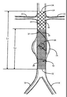
Referring to Figure 1, there is indicated generally by numeral 10 the
preferred
embodiment of the stent/graft constructed in accordance with the present
invention.
The stent/graft 10 is shown in place in a segment of the abdominal aorta 12
having an
aneurysm 14. At its lower end, the abdominal aorta 12 branches into the left
and right
common iliac arteries 16 and 18. Also shown in Figure 1 are renal arteries 20
and 22
leading to the kidneys (not shown).
The stent/graft 10 comprises an innermost tubular structure 23 of a first
length
(L1) and at least one further tubular structure 26 of a length L2, both
structures having
a predetermined similar diameter. The stent/graft may have an overall length
L, in the
range of 12 to 16 cm, preferably 14 cm. and a length L2 in the range of 8 to
12 cm,
preferably 10 cm.
The innermost tubular structure comprises a first plurality of braided wire
strands 24, preferably of a shape memory alloy, such as Nitinol. The braid
comprising
the innermost tubular structure 23 has a predetermined pick and pitch to
define
openings through the structure that are sufficiently large so as not to
materially
impede blood flow through its fenestrated wall. The wire strands may have a
diameter
in a range of from 0.002 to 0.012 inch and tubular structure 23, is designed
to provide
an adequate radial outward force necessary for self-expansion /vascular
support
/anchoring of the stent/graft 10. This could also be the outer graft layer if
the layers
CA 02607516 2009-02-27
11
are tied together so that the expansion of the other layers follows suit with
the
expansion of the frame.
To achieve adequate vascular support for anchoring the stent/graft in the
region of the renal arteries, the innermost tubular structure's self expanding
diameter
is sized to be larger than the native vessel diameter to exert a holding force
against the
native vessel. This oversizing of the stent/graft diameter may be in the range
of 10-
20%. This oversizing may, alternatively, be limited to the portion of the
device
involved in anchoring near the renal arteries. This may be beneficial since it
is not
desirable to put an outward radial force on the aneurismal section.
At least one further tubular structure 26, with a predetermined length portion
(L2) and a predetermined diameter, is placed in coaxial surrounding
relationship of the
innermost tubular structure where the further tubular structure 26 is of a
shorter length
than that of the innermost tubular structure 23.
The further tubular structure surrounding the innermost tubular structure is
comprised of a second plurality of braided wire strands 28 that is
significantly greater
in number than the first plurality of braided wire strands making up the
innermost
tubular structure. The strands 28 are also of a shape memory alloy and they
are
braided so as to have a pick and pitch to define openings sufficiently small
so as to
substantially preclude blood flow through the wall thereof.
Without limitation, the innermost tubular structure 23 may comprise 36-144,
(preferably 72) strands of wire ranging in diameter from 0.002 to 0.010 in.
(preferably
0.006) woven so as to exhibit fenestrations with an area of about 0.001 to
0.002 sq.
in., preferably 0.0015 sq. in. The further tubular structure 26 may then
comprise 72 -
288, preferably 144 wires ranging in diameter from 0.001 to 0.005 in.,
preferably
0.0025 in., formed of a shape memory alloy, such as Nitinol, that are braided
so as to
define significantly smaller fenestrations having an area of from 0.00015 to
0.0003 sq.
in., preferably 0.00025 sq. in., which are sufficiently small so as to
substantially
preclude blood flow through the portion of the stent/graft 10 of the length
L2. Inner
and outer braided layers have pitch rates that are about equal to obtain
desirable
collapse and expansion characteristics, such as maintaining a uniform overall
length.
CA 02607516 2007-10-24
12
It should be noted that as used herein "substantially preclude or impede flow"
shall
mean, functionally, that blood flow may occur for a short time, preferably
about 15-45
minutes, but that the body's clotting mechanism or protein or other body
deposits on
the braided wires results in occlusion or flow stoppage after this initial
time period.
This may be clinically represented by no contrast flow through the stent/graft
wall
after the 15-45 minute period as viewed by fluoroscopy after a contrast
injection.
In accordance with the present invention, even smaller fenestrations can be
provided over the length L2 by having a second, outermost, tubular braided
structure
30 coaxially surrounding the intermediate tubular structure 26 that surrounds
the
innermost tubular structure 23. This second and outermost tubular structure 30
would
also extend the length L2 (slightly shorter due to wire end offset) and may be
identical
in its braided configuration to the further tubular structure 26, e.g., 72-
288,
preferably144 strands of 0.001 to 0.005 diameter Nitinol wire braided so as to
have
effectively 0.0001 (.010 in. X.010 in.) sq. in. openings.
The stent/graft tubular structural layers are "stitched" together in the
center of
the structure using platinum radiopaque stranded wire, diameter range of 0.002
to
0.006, preferably 0.003 in., at 3-5 locations around the circumference. This
has two
benefits - it allows the implanting medical professional to know where the
center of
the graft is for centering the stent/graft in the center of the aneurysm and
it also allows
the multiple braided layers to more freely move during collapse and expansion.
By
holding the layers together in the center, the relative position of the layers
in relation
to one another are fixed, however, the ends of the layers can float somewhat
freely in
relation to one another to allow for full radial deployment without much
interaction
with one another. If braid pitches between layers are not identical, stitching
the graft
in more than one location along the length leads to bunching which leads to
high
profiles and undesirable interaction between the braided layers. Platinum wire
or
ribbon stitching may also be placed at locations other than the center of the
stent/graft,
if the braided tubular structures have substantially the same pitch angle.
Other types of
connectors, such as radiopaque rivets may be used as an alternative to
platinum
wire/ribbon. Not all connectors need to be radiopaque.
CA 02607516 2008-10-22
13
It is also contemplated that one or more radial (helical) stitches, as at 37
in
Figure 1, may be used to hold all braided layers tightly together along the
entire length
of the graft (rather than just in the center) to prevent any separation of the
layers once
the device is implanted. The radial stitches could be Nitinol and could be
heat set at
the same time the graft is heat set. These helical stitches could be sewn into
the braid
at approximately the same pitch as the braided layers. One could stitch to
follow
every 3ra or 5th wire, for example, and weave in and out of the braid in a
helical
pattern until the entire length of the braid was sewn. The inner structure
wires would
likely be followed with this stitching.
It is contemplated that the stent/graft 10 be fabricated using the method set
out
in U.S. Patent 6,123,715 to Curtis Amplatz. The innermost structure 23 could
be
braided to form a tubular fabric as would the further tubular structure or
structures 26.
The outer braided tube or tubes would then be concentrically disposed over the
innermost tubular structure and the combination would be placed about a
cylindrical
mandrel of the desired outer diameter for the stent/graft. This assembly would
then be
heated to a predetermined temperature and for a length of time sufficient to
heat set
the tubular structures to the diameter of the mandrel. The opposite free ends
32, 34 of
the strands comprising the innermost tubular structure 23 may be flared
radially
outward by 100 to 30 to provide improved apposition with the inner wall of
the aorta.
Following removal from the mold, the two or more coaxial braided tubes may
be held together by one or more connecting members, e.g., a few radiopaque
platinum
wires or, alternatively, suture stitches. Such stitches are preferably placed
at
approximately the mid-point of the length of the tubular structure to
facilitate
fluoroscopic placement and so that the stent/graft can be elongated both in
the
proximal and distal direction for insertion into a delivery system. As such,
the suture
stitches successfully hold the coaxially braided tubes together yet permit
portions of
the individual coaxial braided tubes to move relative to each other as the
stent is
stretched for insertion into the delivery system and as it self-expands to
engage the
aortic wall and budge the aneurysm.
CA 02607516 2008-10-22
14
It is also contemplated that the thus-formed stent/graft can be coated with a
drug-eluting polymer for reducing embolization or displacement of grumous
material.
The drug-eluting polymer may be selectively coated on the open weave or closed
weave segments.
In use, the thus-formed stent would be releasably affixed at its proximal end
to
a pusher catheter in the manner described in Amplatz' published application
US 2006/0253184 Al entitled "System for the Controlled Delivery of Stents and
Grafts". The stent would then be drawn into a lumen of an intravascular
delivery
catheter. The delivery catheter would be introduced into the patient using the
well-
known Seldinger technique and then threaded through the vascular system until
a
distal end of the delivery catheter is proximate an aneurysm to be treated.
With the
stent and the pusher catheter held stationary, the delivery catheter is drawn
in the
proximal direction to eject the stent from the distal end of the delivery
catheter where
the stent then self-expands to engage the aortic wall with the portion of
length L2 in
Figure 1 bridging the aneurysm being treated. The portion of the innermost
tubular
structure that extends beyond the distal end of the further tubular structure
may
overlay the ostia of the renal arteries 20 and 22. However, because of the
open weave
construction of that portion of the inner tubular structure, it does not
significantly
impede blood flow through the renal arteries or create a stenosis. The added
length of
the stent/graft 10 provided by the extension of the innermost tubular
structure 23
beyond the distal end of the further layer(s) 26, 30 serves to better
stabilize the
stent/graft within the abdominal aorta, preventing its displacement before
endothelialization can occur.
Alternative embodiments are shown in Figures 2, 3, & 4 A,B,C. In all of the
alternative embodiments, the individual parameters regarding number of wires,
wire
diameter, pitch, and fenestration size for either a primary radial support
tubular
member or a non-primary radial support tubular member are similar to, but not
limited
to, those parameters as described in the AAA stent/graft preferred embodiment,
Figure
1.
In Figure 2 the innermost tubular structure 40 and at least one further
tubular
CA 02607516 2007-10-24
structure 42 and 44 are shown as having substantially the same length, with
the
exception of the wire end offset of adjacent structures, whereby the wire ends
are
offset toward the center of the stent/graft. The offset may range from 0.020
to 0.100
in., and preferably is about 0.050 in.
5 In another embodiment of the stent/graft shown in Figure 3, the stent/graft
has
a middle portion 50 more open to flow than the end portions 52 and 54. The
middle
portion 50 in this preferred embodiment represents the primary radial support
layer
only, with at least one further tubular structure on both ends from the middle
more
open fenestration portion. This particular embodiment may be suited, for
example, to
10 a carotid lesion application, where the stent/graft is positioned across
the carotid
bifurcation in such a manner that the middle, more open fenestration portion
allows
relatively unrestricted blood flow from the common carotid through the wall of
the
stent/graft into the external carotid artery 56 while axial flow proceeds to
the internal
carotid artery.
15 Figures 4A, B and C show alternative embodiments where the primary radial
support structure, represented as a heavy line, varies in its placement
between the
innermost structural layer (Figure 4A), middle structural layer (Figure 4B)
and
outermost structural layer (Figure 4C). These construction alternatives could
be
applied to any of the embodiments shown in Figures 1, 2 or 3.
Each embodiment may be alternatively constructed by using materials having
elastic properties other than Nitinol, such as spring stainless steel,
Elgiloy, or hastalloy
or a mixture of metal and plastic fibers. The metal and plastic fibers may be
combined
in the same layer; alternatively the device may be constructed in such a
manner that
each layer is made from a different material. Depending on the individual
material
selected, the wire diameter, number of wires and pitch may be altered to
achieve the
desired properties of the stent/graft. In any of the embodiments, as in that
of Figure 2,
the individual tubular members may optionally have the end wires heat set
radially
outward 10-30 degrees from the longitudinal axis of the stent/graft, to
improve end
wire seating and anchoring in the vessel. This also makes it less likely that
passage of
subsequent catheters through the stent/graft will hang up on the wire ends.
CA 02607516 2007-10-24
16
Another embodiment contemplated is a stent/graft where there are two further
braided tubular structures which are not primary radial support structures
with the
variation being that the two further structures are formed from one tubular
member
partially averted to create two layers. Figure 4C shows an embodiment where
the
innermost two layers are formed from a single tubular braid of a length 21
that is
averted to form a structure of a length L. Heat setting the folded end
facilitates this
structure.
A further embodiment of the stent/graft pertains to all of the previous
embodiments but is differentiated by the manner in which the stent/graft is
delivered.
In all the previous embodiments the stent graft is a unified device made of
attached
tubular, concentric structures that are all delivered together by a single
delivery
catheter in a single step. In this further embodiment, the individual tubular
structures
are delivered one at a time in-vivo in separate procedural steps starting with
the
outermost tubular structure and next delivering the adjacent structure inside
the
previous structure. In this case the structures are not bonded together by
stitching as
at 62 in Figure 4, but each individual structure may have radiopaque markers
by
stitching to facilitate placing the structure relative to the treatment site.
The markers
may be positioned such that the operator places the markers from various
structures so
they lie in the same plane transverse to the vessel. The stent/graft created
in-vivo by
serial delivery of individual structures is the same as all previous
embodiments with
the exception that the multiple structures are not stitched together, but are
locked in
place by the radial pressure of the innermost layer which would preferably
also be the
primary radial support layer.
This invention has been described herein in considerable detail in order to
comply with the patent statutes and to provide those skilled in the art with
the
information needed to apply the novel principles and to construct and use such
specialized components as are required. However, it is to be understood that
the
invention can be carried out by specifically different equipment and devices,
and that
various modifications, both as to the equipment and operating procedures, can
be
accomplished without departing from the scope of the invention itself.