Language selection

Search

Patent 2607642 Summary

Third-party information liability

Some of the information on this Web page has been provided by external sources. The Government of Canada is not responsible for the accuracy, reliability or currency of the information supplied by external sources. Users wishing to rely upon this information should consult directly with the source of the information. Content provided by external sources is not subject to official languages, privacy and accessibility requirements.

Claims and Abstract availability

Any discrepancies in the text and image of the Claims and Abstract are due to differing posting times. Text of the Claims and Abstract are posted:

  • At the time the application is open to public inspection;
  • At the time of issue of the patent (grant).
(12) Patent: (11) CA 2607642
(54) English Title: METHOD FOR MAKING A SHAPED FLEXIBLE TUBE AND THE SHAPED FLEXIBLE TUBE MADE THEREBY
(54) French Title: METHODE DE FABRICATION D'UN TUBE SOUPLE FORME ET LE TUBE SOUPLE FORME AVEC CETTE METHODE
Status: Granted and Issued
Bibliographic Data
(51) International Patent Classification (IPC):
  • B32B 1/08 (2006.01)
  • B29D 23/00 (2006.01)
  • B32B 15/08 (2006.01)
  • B32B 27/08 (2006.01)
(72) Inventors :
  • ALDINIO-COLBACHINI, GIUSEPPE (Italy)
(73) Owners :
  • IVG COLBACHINI S.P.A.
(71) Applicants :
  • IVG COLBACHINI S.P.A. (Italy)
(74) Agent: FINLAYSON & SINGLEHURST
(74) Associate agent:
(45) Issued: 2013-01-08
(22) Filed Date: 2007-10-24
(41) Open to Public Inspection: 2008-05-08
Examination requested: 2010-04-23
Availability of licence: N/A
Dedicated to the Public: N/A
(25) Language of filing: English

Patent Cooperation Treaty (PCT): No

(30) Application Priority Data:
Application No. Country/Territory Date
MI2006A 002141 (Italy) 2006-11-08

Abstracts

English Abstract


A flexible tube comprises a tubular body made of
a curable flexible material, having at least an elbow
shape, and made by a double curing, the first on a straight
mandrel, and the second on a shaped cylindric core, to
provide the tube with a desired configuration. With
respect to the conventional art in this field, the
invention provides the advantage that the shaped tube made
thereby is directly provided, at the end portion thereof,
with the required fittings, without the need of performing
auxiliary processing steps to clamp the fittings.


French Abstract

Tube flexible comprenant un corps tubulaire composé d'un matériau flexible vulcanisable, ayant au moins une forme coudée, et fabriqué par double vulcanisation, la première sur un mandrin droit et la seconde sur un cour de forme cylindrique, pour donner au tube une configuration souhaitée. Par rapport à l'art classique dans ce domaine, l'invention a pour avantage le fait que le tube formé ainsi fabriqué est directement pourvu, au niveau de sa portion terminale, des raccords nécessaires, sans avoir à subir des étapes de traitement secondaires pour la fixation des raccords par serrage.

Claims

Note: Claims are shown in the official language in which they were submitted.

7
WHAT IS CLAIMED IS:
1. A method for making a shaped flexible tube, made of at least a
curable material and provided with fitting end portions assembled to the
end portions of said shaped tube, characterized in that said method
comprises the step of twice curing said tube, a first curing being
carried out on the tube formed on a straight mandrel, and the second
curing being performed on a shaped cylindrical core element to provide
the tube with a desired shape, said fitting ends portions being assembled
as a single piece to the end portions of said shaped tube simultaneously
with said step for forming said tube on said straight mandrel.
2. A method according to claim 1, characterized in that said method
comprises the steps of:
- forming said tube by winding, on a straight mandrel, at least
a constructional curable material for said tube;
- subjecting said tube to the first curing, on the said straight
mandrel;
- transferring the cured tube to the shaped cylindric core
element;
- subjecting said tube on said shaped cylindric core to the
second curing; and
- separating, from said shaped cylindric core, the curved tube
made by said second curing.
3. A shaped flexible tube, characterized in that said shaped flexible
tube is made by a method according to claim 1 or 2.
4. The tube according to claim 3, characterized in that said tube
comprises a tubular body (2) made of a flexible curable material, having
at least an elbow shape (5), said tube further comprising fitting end
portions (3, 4) built-in as a single piece at corresponding end portions
of said tube (1).

8
5. The tube according to claim 4, characterized in that said fitting
end portions are taken from the group consisting of: a rubber heel
element (3), a steel end piece (17), a coated cured fitting (18), a
rubber flange (19), and a cured fitting element (20).
6. The tube according to claim 5, characterized in that said tubular
body (2) includes a first inner rubber layer (6), having applied thereon
a first fabric layer (7) made of a pressure resistant fabric material,
a second rubber layer (8) , a further fabric layer (9) and a third rubber
layer (10).
7. The tube according to claim 6, characterized in that said further
fabric layer (9) is the same as the first fabric layer (7).
8. The tube according to claim 7, characterized in that said tubular
body comprises, above said third layer (10), a fourth layer (11).
9. The tube according to claim 8, characterized in that said tubular
body further comprises, above said fourth layer (11), an outer coating
layer (12).
10. The tube according to claim 9, wherein the outer coating layer (12)
is of a rubber material.

Description

Note: Descriptions are shown in the official language in which they were submitted.


CA 02607642 2007-10-24
METHOD FOR MAKING A SHAPED FLEXIBLE TUBE AND THE SHAPED
FLEXIBLE TUBE MADE THEREBY
BACKGROUND OF THE INVENTION
The present invention relates to a novel method
for making shaped flexible tubes or hoses, in
particular curved flexible tubes.
The invention also relates to the shaped
flexible tube made by the inventive method.
The field of the invention is that of the
methods used for making shaped flexible tubes in
general, in particular tubes including either one or
more bent portions, and which are made of a curable
material.
At present, the flexible tubes of the above
mentioned type, made of a flexible elastomeric curable
material, such as rubber and the like, as they are
industrially made by a method different from a straight
mandrel method, have free end portions thereof, that is
end portions which are lacking of possible fittings or
"rubber heel members", made as a single piece, and
which are usually necessary for coupling the tube to
target utilizer devices.
Thus, conventional curved tubes having the above
disclosed construction require auxiliary clamping
operations, for clamping the desired fittings which,
accordingly, are not structurally joined or integral
with the body of the tube.
Thus, prior tubes of the above disclosed pipes
are affected by drawbacks, related to the mentioned
requirements of performing auxiliary processing

CA 02607642 2012-05-16
2
operations on said tubes, and due to the further
requirement of using auxiliary elements such as clamping
bands, ring-nuts and the like.
To overcome the above mentioned drawbacks, it is
known in the art to make flexible pipes or hoses on a
straight mandrel, the pipes being held in a desired curved
or bent position by a metal coil insert, operating to
receive and hold the desired shape of the tube.
Such an approach, however, has the drawback of
requiring an additional provision of a metal coil or spiral
element to be built-in or embedded in the pipe
construction; such a coil element, actually, is sometimes
undesirable, since such a coil or spiral element would
negatively affect the end weight of the tube and its making
costs.
SUMMARY OF THE INVENTION
Accordingly, the present invention seeks to
provide a novel method for making shaped flexible tubes or
hoses, which, with respect to prior hose or tube making
methods, allows to include the end required fittings at the
end of the tube, directly as the latter is made.
Further, the present invention seeks to provide
such a shaped flexible tube which comprises tube fittings
made as a single-piece at the ends of the tube.
In a broad aspect, the invention pertains to a
method for making a shaped flexible tube, made of at least
a curable material and provided with fitting end portions
assembled to the end portions of the shaped tube. The
method comprises the step of twice curing the tube, a first
curing being carried out on the tube formed on a straight
mandrel, and the second curing being performed on a shaped
cylindrical core element to provide the tube with a desired

CA 02607642 2012-05-16
3
shape. The fitting ends portions are assembled as a single
piece to the end portions of the shaped tube simultaneously
with the step for forming the tube on the straight mandrel.
With respect to conventional flexible tube making
methods, the inventive method provides the advantage of
making a shaped flexible tube which is already provided, at
the end portions thereof, with the required tube fittings,
and this without the need of performing auxiliary
processing operations for clamping the tube fittings to the
tube body.
Another advantage of the invention is that the
inventive shaped tube is made on a straight mandrel, that
is by a method which, at present, provides an end product
of a very high quality.
BRIEF DESCRIPTION OF THE DRAWINGS
The above mentioned aspects, as well as yet other
aspects, advantages and characteristics of the invention
will become more apparent hereinafter from the following
disclosure of a preferred embodiment of a method for making
a flexible tube according to the invention, and a tube made
thereby, which are hereinafter disclosed with reference to
the figures of the accompanying drawings, given only by way
of a non limitative example.
In the drawings:
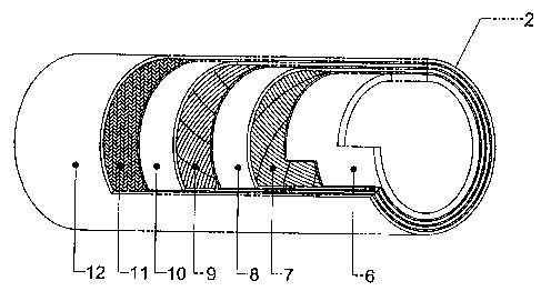
Figure 1 is a broken-away view showing the
construction of a flexible tube according to the present
invention;
Figure 2 shows the tube of figure 1, made on a
straight mandrel and including integral fitting end

CA 02607642 2007-10-24
4
portions;
Figures 3 to 6 show the operating steps of the
method for making the tube of figure 1;
Figure 7 shows an exemplary embodiment of the
tube made by the method shown in the preceding figures;
Figures 8 to 11 are cross-sectional views
showing some exemplary embodiments of the flexible tube
made by the method according to the invention.
DESCRIPTION OF THE PREFERRED EMBODIMENTS
The flexible tube or hose according to the
present invention has been generally indicated in the
figure 7 by the reference number 1.
Said flexible tube comprises a tubular body 2,
made of a flexible cured material, having connection
end portions 3, 4 and curved at a tube elbow 5.
More specifically, as clearly shown in figure 1,
the tubular body 2 of the inventive flexible tube
comprises a first inner rubber layer 6 (a flexible
curable material), thereon are applied or coated, or
overlapped, in succession and by a straight mandrel
making method, a layer 7 made of a pressure resistant
fabric material, a rubber layer 8, a further fabric
layer 9 similar to the layer 7, a further rubber layer
10, yet another layer 11 of a material adapted to
resist against high temperatures, and an outer covering
layer 12 made of rubber or other suitable materials.
At the start of the making of the tube 1, as is
shown in figures 2 and 3, the tubular body 2 is formed
on a straight mandrel 13, with an integral making of
fitting ends 3, 5 at the corresponding end portions of

CA 02607642 2007-10-24
the tubular body 2.
The thus made tube is then subjected to a curing
operation, for a first time, in a curing oven 14
(figure 4).
5 At the outlet of the curing oven 14 a
rectilinear flexible tube is thus obtained, which is
then assembled on a curved cylindric core element 15,
designed for providing the tube with the shape of the
above mentioned elbow 5.
The core element or assembly 15, with the tube
engaged therein, is then caused to pass through a
further oven 16, which will perform a second curing
step on the tube already cured in the curing oven 14,
thereby permanently providing the tube 1 with its bent
or curved end shape, as shown in figure 7.
At the end of the above mentioned operation, the
flexible tube 1 is withdrawn or separated from said
core element 15.
Thus, by the inventive method, the shaped
flexible tube 1 of figure 7 can be made by a straight
mandrel tube making method, with an integrated curing
step for curing the tube on a curved or bent core
element, thereby simultaneously providing both a tube
having the desired shape, and integral fitting
elements, in a single piece with the tube body, at the
end portions of the tube body.
In particular, in the embodiments shown in
figures 8 to 11, in the end portions of the shaped
flexible tube 1 are respectively embedded or built-in,
an end-piece 17, made of a steel material, a flange 18
with a rubber core (coated cured fitting element), a
further rubber flange 19, and yet another flange 20

CA 02607642 2007-10-24
6
(cured fitting element).
The method according to the invention will be
disclosed hereinafter with reference to some exemplary
embodiments thereof, which are herein shown only by way
of indicate examples, without limiting the scope of the
invention.
Example 1
The tube of figure 7
- design size of the straight mandrel 13:
diameter 100 mm:
- fitting end 3,4: "rubber heel elements";
- design size of the curved or bent core 15:
diameter 100 mm; bending radius 400 mm; angle
45 .
Example 2
The tube of figure 9
- design size of the straight mandrel 13: outer
diameter 130 mm:
- flanges 3,4: coated cured fittings;
- design size of the curved core 15: outer
diameter 130 mm; bending radius 500 mm; angle
90 .
It should be apparent that the invention is not
limited to the embodiments of the tube shown in the
figures and hereinabove disclosed, since it is
susceptible to several modifications and variations all
of which will come within the scope of the invention.

Representative Drawing
A single figure which represents the drawing illustrating the invention.
Administrative Status

2024-08-01:As part of the Next Generation Patents (NGP) transition, the Canadian Patents Database (CPD) now contains a more detailed Event History, which replicates the Event Log of our new back-office solution.

Please note that "Inactive:" events refers to events no longer in use in our new back-office solution.

For a clearer understanding of the status of the application/patent presented on this page, the site Disclaimer , as well as the definitions for Patent , Event History , Maintenance Fee  and Payment History  should be consulted.

Event History

Description Date
Maintenance Fee Payment Determined Compliant 2024-10-17
Maintenance Request Received 2024-10-17
Common Representative Appointed 2019-10-30
Grant by Issuance 2013-01-08
Inactive: Cover page published 2013-01-07
Pre-grant 2012-09-19
Inactive: Final fee received 2012-09-19
Notice of Allowance is Issued 2012-06-12
Letter Sent 2012-06-12
Notice of Allowance is Issued 2012-06-12
Inactive: Approved for allowance (AFA) 2012-06-07
Amendment Received - Voluntary Amendment 2012-05-16
Inactive: S.30(2) Rules - Examiner requisition 2011-12-01
Letter Sent 2010-05-13
Request for Examination Requirements Determined Compliant 2010-04-23
Request for Examination Received 2010-04-23
All Requirements for Examination Determined Compliant 2010-04-23
Application Published (Open to Public Inspection) 2008-05-08
Inactive: Cover page published 2008-05-07
Inactive: IPC assigned 2008-04-23
Inactive: First IPC assigned 2008-04-23
Inactive: IPC assigned 2008-04-23
Application Received - Regular National 2007-11-27
Inactive: Filing certificate - No RFE (English) 2007-11-27
Filing Requirements Determined Compliant 2007-11-27

Abandonment History

There is no abandonment history.

Maintenance Fee

The last payment was received on 2012-10-11

Note : If the full payment has not been received on or before the date indicated, a further fee may be required which may be one of the following

  • the reinstatement fee;
  • the late payment fee; or
  • additional fee to reverse deemed expiry.

Please refer to the CIPO Patent Fees web page to see all current fee amounts.

Owners on Record

Note: Records showing the ownership history in alphabetical order.

Current Owners on Record
IVG COLBACHINI S.P.A.
Past Owners on Record
GIUSEPPE ALDINIO-COLBACHINI
Past Owners that do not appear in the "Owners on Record" listing will appear in other documentation within the application.
Documents

To view selected files, please enter reCAPTCHA code :


To view images, click a link in the Document Description column. To download the documents, select one or more checkboxes in the first column and then click the "Download Selected in PDF format (Zip Archive)" or the "Download Selected as Single PDF" button.

List of published and non-published patent-specific documents on the CPD .

If you have any difficulty accessing content, you can call the Client Service Centre at 1-866-997-1936 or send them an e-mail at CIPO Client Service Centre.


Document
Description 
Date
(yyyy-mm-dd) 
Number of pages   Size of Image (KB) 
Abstract 2007-10-24 1 15
Description 2007-10-24 6 195
Claims 2007-10-24 2 61
Drawings 2007-10-24 11 161
Representative drawing 2008-04-24 1 20
Cover Page 2008-04-29 1 51
Abstract 2012-05-16 1 14
Description 2012-05-16 6 200
Claims 2012-05-16 2 59
Cover Page 2012-12-27 1 49
Confirmation of electronic submission 2024-10-17 1 61
Filing Certificate (English) 2007-11-27 1 157
Reminder of maintenance fee due 2009-06-29 1 110
Acknowledgement of Request for Examination 2010-05-13 1 177
Commissioner's Notice - Application Found Allowable 2012-06-12 1 161
Correspondence 2012-09-19 1 39
Change of agent 2017-10-17 2 60