Sélection de la langue

Search

Sommaire du brevet 2607642 

Énoncé de désistement de responsabilité concernant l'information provenant de tiers

Une partie des informations de ce site Web a été fournie par des sources externes. Le gouvernement du Canada n'assume aucune responsabilité concernant la précision, l'actualité ou la fiabilité des informations fournies par les sources externes. Les utilisateurs qui désirent employer cette information devraient consulter directement la source des informations. Le contenu fourni par les sources externes n'est pas assujetti aux exigences sur les langues officielles, la protection des renseignements personnels et l'accessibilité.

Disponibilité de l'Abrégé et des Revendications

L'apparition de différences dans le texte et l'image des Revendications et de l'Abrégé dépend du moment auquel le document est publié. Les textes des Revendications et de l'Abrégé sont affichés :

  • lorsque la demande peut être examinée par le public;
  • lorsque le brevet est émis (délivrance).
(12) Brevet: (11) CA 2607642
(54) Titre français: METHODE DE FABRICATION D'UN TUBE SOUPLE FORME ET LE TUBE SOUPLE FORME AVEC CETTE METHODE
(54) Titre anglais: METHOD FOR MAKING A SHAPED FLEXIBLE TUBE AND THE SHAPED FLEXIBLE TUBE MADE THEREBY
Statut: Accordé et délivré
Données bibliographiques
(51) Classification internationale des brevets (CIB):
  • B32B 1/08 (2006.01)
  • B29D 23/00 (2006.01)
  • B32B 15/08 (2006.01)
  • B32B 27/08 (2006.01)
(72) Inventeurs :
  • ALDINIO-COLBACHINI, GIUSEPPE (Italie)
(73) Titulaires :
  • IVG COLBACHINI S.P.A.
(71) Demandeurs :
  • IVG COLBACHINI S.P.A. (Italie)
(74) Agent: FINLAYSON & SINGLEHURST
(74) Co-agent:
(45) Délivré: 2013-01-08
(22) Date de dépôt: 2007-10-24
(41) Mise à la disponibilité du public: 2008-05-08
Requête d'examen: 2010-04-23
Licence disponible: S.O.
Cédé au domaine public: S.O.
(25) Langue des documents déposés: Anglais

Traité de coopération en matière de brevets (PCT): Non

(30) Données de priorité de la demande:
Numéro de la demande Pays / territoire Date
MI2006A 002141 (Italie) 2006-11-08

Abrégés

Abrégé français

Tube flexible comprenant un corps tubulaire composé d'un matériau flexible vulcanisable, ayant au moins une forme coudée, et fabriqué par double vulcanisation, la première sur un mandrin droit et la seconde sur un cour de forme cylindrique, pour donner au tube une configuration souhaitée. Par rapport à l'art classique dans ce domaine, l'invention a pour avantage le fait que le tube formé ainsi fabriqué est directement pourvu, au niveau de sa portion terminale, des raccords nécessaires, sans avoir à subir des étapes de traitement secondaires pour la fixation des raccords par serrage.


Abrégé anglais


A flexible tube comprises a tubular body made of
a curable flexible material, having at least an elbow
shape, and made by a double curing, the first on a straight
mandrel, and the second on a shaped cylindric core, to
provide the tube with a desired configuration. With
respect to the conventional art in this field, the
invention provides the advantage that the shaped tube made
thereby is directly provided, at the end portion thereof,
with the required fittings, without the need of performing
auxiliary processing steps to clamp the fittings.

Revendications

Note : Les revendications sont présentées dans la langue officielle dans laquelle elles ont été soumises.


7
WHAT IS CLAIMED IS:
1. A method for making a shaped flexible tube, made of at least a
curable material and provided with fitting end portions assembled to the
end portions of said shaped tube, characterized in that said method
comprises the step of twice curing said tube, a first curing being
carried out on the tube formed on a straight mandrel, and the second
curing being performed on a shaped cylindrical core element to provide
the tube with a desired shape, said fitting ends portions being assembled
as a single piece to the end portions of said shaped tube simultaneously
with said step for forming said tube on said straight mandrel.
2. A method according to claim 1, characterized in that said method
comprises the steps of:
- forming said tube by winding, on a straight mandrel, at least
a constructional curable material for said tube;
- subjecting said tube to the first curing, on the said straight
mandrel;
- transferring the cured tube to the shaped cylindric core
element;
- subjecting said tube on said shaped cylindric core to the
second curing; and
- separating, from said shaped cylindric core, the curved tube
made by said second curing.
3. A shaped flexible tube, characterized in that said shaped flexible
tube is made by a method according to claim 1 or 2.
4. The tube according to claim 3, characterized in that said tube
comprises a tubular body (2) made of a flexible curable material, having
at least an elbow shape (5), said tube further comprising fitting end
portions (3, 4) built-in as a single piece at corresponding end portions
of said tube (1).

8
5. The tube according to claim 4, characterized in that said fitting
end portions are taken from the group consisting of: a rubber heel
element (3), a steel end piece (17), a coated cured fitting (18), a
rubber flange (19), and a cured fitting element (20).
6. The tube according to claim 5, characterized in that said tubular
body (2) includes a first inner rubber layer (6), having applied thereon
a first fabric layer (7) made of a pressure resistant fabric material,
a second rubber layer (8) , a further fabric layer (9) and a third rubber
layer (10).
7. The tube according to claim 6, characterized in that said further
fabric layer (9) is the same as the first fabric layer (7).
8. The tube according to claim 7, characterized in that said tubular
body comprises, above said third layer (10), a fourth layer (11).
9. The tube according to claim 8, characterized in that said tubular
body further comprises, above said fourth layer (11), an outer coating
layer (12).
10. The tube according to claim 9, wherein the outer coating layer (12)
is of a rubber material.

Description

Note : Les descriptions sont présentées dans la langue officielle dans laquelle elles ont été soumises.

CA 02607642 2007-10-24
METHOD FOR MAKING A SHAPED FLEXIBLE TUBE AND THE SHAPED
FLEXIBLE TUBE MADE THEREBY
BACKGROUND OF THE INVENTION
The present invention relates to a novel method
for making shaped flexible tubes or hoses, in
particular curved flexible tubes.
The invention also relates to the shaped
flexible tube made by the inventive method.
The field of the invention is that of the
methods used for making shaped flexible tubes in
general, in particular tubes including either one or
more bent portions, and which are made of a curable
material.
At present, the flexible tubes of the above
mentioned type, made of a flexible elastomeric curable
material, such as rubber and the like, as they are
industrially made by a method different from a straight
mandrel method, have free end portions thereof, that is
end portions which are lacking of possible fittings or
"rubber heel members", made as a single piece, and
which are usually necessary for coupling the tube to
target utilizer devices.
Thus, conventional curved tubes having the above
disclosed construction require auxiliary clamping
operations, for clamping the desired fittings which,
accordingly, are not structurally joined or integral
with the body of the tube.
Thus, prior tubes of the above disclosed pipes
are affected by drawbacks, related to the mentioned
requirements of performing auxiliary processing

CA 02607642 2012-05-16
2
operations on said tubes, and due to the further
requirement of using auxiliary elements such as clamping
bands, ring-nuts and the like.
To overcome the above mentioned drawbacks, it is
known in the art to make flexible pipes or hoses on a
straight mandrel, the pipes being held in a desired curved
or bent position by a metal coil insert, operating to
receive and hold the desired shape of the tube.
Such an approach, however, has the drawback of
requiring an additional provision of a metal coil or spiral
element to be built-in or embedded in the pipe
construction; such a coil element, actually, is sometimes
undesirable, since such a coil or spiral element would
negatively affect the end weight of the tube and its making
costs.
SUMMARY OF THE INVENTION
Accordingly, the present invention seeks to
provide a novel method for making shaped flexible tubes or
hoses, which, with respect to prior hose or tube making
methods, allows to include the end required fittings at the
end of the tube, directly as the latter is made.
Further, the present invention seeks to provide
such a shaped flexible tube which comprises tube fittings
made as a single-piece at the ends of the tube.
In a broad aspect, the invention pertains to a
method for making a shaped flexible tube, made of at least
a curable material and provided with fitting end portions
assembled to the end portions of the shaped tube. The
method comprises the step of twice curing the tube, a first
curing being carried out on the tube formed on a straight
mandrel, and the second curing being performed on a shaped
cylindrical core element to provide the tube with a desired

CA 02607642 2012-05-16
3
shape. The fitting ends portions are assembled as a single
piece to the end portions of the shaped tube simultaneously
with the step for forming the tube on the straight mandrel.
With respect to conventional flexible tube making
methods, the inventive method provides the advantage of
making a shaped flexible tube which is already provided, at
the end portions thereof, with the required tube fittings,
and this without the need of performing auxiliary
processing operations for clamping the tube fittings to the
tube body.
Another advantage of the invention is that the
inventive shaped tube is made on a straight mandrel, that
is by a method which, at present, provides an end product
of a very high quality.
BRIEF DESCRIPTION OF THE DRAWINGS
The above mentioned aspects, as well as yet other
aspects, advantages and characteristics of the invention
will become more apparent hereinafter from the following
disclosure of a preferred embodiment of a method for making
a flexible tube according to the invention, and a tube made
thereby, which are hereinafter disclosed with reference to
the figures of the accompanying drawings, given only by way
of a non limitative example.
In the drawings:
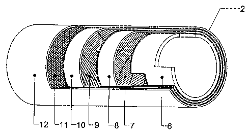
Figure 1 is a broken-away view showing the
construction of a flexible tube according to the present
invention;
Figure 2 shows the tube of figure 1, made on a
straight mandrel and including integral fitting end

CA 02607642 2007-10-24
4
portions;
Figures 3 to 6 show the operating steps of the
method for making the tube of figure 1;
Figure 7 shows an exemplary embodiment of the
tube made by the method shown in the preceding figures;
Figures 8 to 11 are cross-sectional views
showing some exemplary embodiments of the flexible tube
made by the method according to the invention.
DESCRIPTION OF THE PREFERRED EMBODIMENTS
The flexible tube or hose according to the
present invention has been generally indicated in the
figure 7 by the reference number 1.
Said flexible tube comprises a tubular body 2,
made of a flexible cured material, having connection
end portions 3, 4 and curved at a tube elbow 5.
More specifically, as clearly shown in figure 1,
the tubular body 2 of the inventive flexible tube
comprises a first inner rubber layer 6 (a flexible
curable material), thereon are applied or coated, or
overlapped, in succession and by a straight mandrel
making method, a layer 7 made of a pressure resistant
fabric material, a rubber layer 8, a further fabric
layer 9 similar to the layer 7, a further rubber layer
10, yet another layer 11 of a material adapted to
resist against high temperatures, and an outer covering
layer 12 made of rubber or other suitable materials.
At the start of the making of the tube 1, as is
shown in figures 2 and 3, the tubular body 2 is formed
on a straight mandrel 13, with an integral making of
fitting ends 3, 5 at the corresponding end portions of

CA 02607642 2007-10-24
the tubular body 2.
The thus made tube is then subjected to a curing
operation, for a first time, in a curing oven 14
(figure 4).
5 At the outlet of the curing oven 14 a
rectilinear flexible tube is thus obtained, which is
then assembled on a curved cylindric core element 15,
designed for providing the tube with the shape of the
above mentioned elbow 5.
The core element or assembly 15, with the tube
engaged therein, is then caused to pass through a
further oven 16, which will perform a second curing
step on the tube already cured in the curing oven 14,
thereby permanently providing the tube 1 with its bent
or curved end shape, as shown in figure 7.
At the end of the above mentioned operation, the
flexible tube 1 is withdrawn or separated from said
core element 15.
Thus, by the inventive method, the shaped
flexible tube 1 of figure 7 can be made by a straight
mandrel tube making method, with an integrated curing
step for curing the tube on a curved or bent core
element, thereby simultaneously providing both a tube
having the desired shape, and integral fitting
elements, in a single piece with the tube body, at the
end portions of the tube body.
In particular, in the embodiments shown in
figures 8 to 11, in the end portions of the shaped
flexible tube 1 are respectively embedded or built-in,
an end-piece 17, made of a steel material, a flange 18
with a rubber core (coated cured fitting element), a
further rubber flange 19, and yet another flange 20

CA 02607642 2007-10-24
6
(cured fitting element).
The method according to the invention will be
disclosed hereinafter with reference to some exemplary
embodiments thereof, which are herein shown only by way
of indicate examples, without limiting the scope of the
invention.
Example 1
The tube of figure 7
- design size of the straight mandrel 13:
diameter 100 mm:
- fitting end 3,4: "rubber heel elements";
- design size of the curved or bent core 15:
diameter 100 mm; bending radius 400 mm; angle
45 .
Example 2
The tube of figure 9
- design size of the straight mandrel 13: outer
diameter 130 mm:
- flanges 3,4: coated cured fittings;
- design size of the curved core 15: outer
diameter 130 mm; bending radius 500 mm; angle
90 .
It should be apparent that the invention is not
limited to the embodiments of the tube shown in the
figures and hereinabove disclosed, since it is
susceptible to several modifications and variations all
of which will come within the scope of the invention.

Dessin représentatif
Une figure unique qui représente un dessin illustrant l'invention.
États administratifs

2024-08-01 : Dans le cadre de la transition vers les Brevets de nouvelle génération (BNG), la base de données sur les brevets canadiens (BDBC) contient désormais un Historique d'événement plus détaillé, qui reproduit le Journal des événements de notre nouvelle solution interne.

Veuillez noter que les événements débutant par « Inactive : » se réfèrent à des événements qui ne sont plus utilisés dans notre nouvelle solution interne.

Pour une meilleure compréhension de l'état de la demande ou brevet qui figure sur cette page, la rubrique Mise en garde , et les descriptions de Brevet , Historique d'événement , Taxes périodiques et Historique des paiements devraient être consultées.

Historique d'événement

Description Date
Paiement d'une taxe pour le maintien en état jugé conforme 2024-10-17
Requête visant le maintien en état reçue 2024-10-17
Représentant commun nommé 2019-10-30
Accordé par délivrance 2013-01-08
Inactive : Page couverture publiée 2013-01-07
Préoctroi 2012-09-19
Inactive : Taxe finale reçue 2012-09-19
Un avis d'acceptation est envoyé 2012-06-12
Lettre envoyée 2012-06-12
Un avis d'acceptation est envoyé 2012-06-12
Inactive : Approuvée aux fins d'acceptation (AFA) 2012-06-07
Modification reçue - modification volontaire 2012-05-16
Inactive : Dem. de l'examinateur par.30(2) Règles 2011-12-01
Lettre envoyée 2010-05-13
Exigences pour une requête d'examen - jugée conforme 2010-04-23
Requête d'examen reçue 2010-04-23
Toutes les exigences pour l'examen - jugée conforme 2010-04-23
Demande publiée (accessible au public) 2008-05-08
Inactive : Page couverture publiée 2008-05-07
Inactive : CIB attribuée 2008-04-23
Inactive : CIB en 1re position 2008-04-23
Inactive : CIB attribuée 2008-04-23
Demande reçue - nationale ordinaire 2007-11-27
Inactive : Certificat de dépôt - Sans RE (Anglais) 2007-11-27
Exigences de dépôt - jugé conforme 2007-11-27

Historique d'abandonnement

Il n'y a pas d'historique d'abandonnement

Taxes périodiques

Le dernier paiement a été reçu le 2012-10-11

Avis : Si le paiement en totalité n'a pas été reçu au plus tard à la date indiquée, une taxe supplémentaire peut être imposée, soit une des taxes suivantes :

  • taxe de rétablissement ;
  • taxe pour paiement en souffrance ; ou
  • taxe additionnelle pour le renversement d'une péremption réputée.

Veuillez vous référer à la page web des taxes sur les brevets de l'OPIC pour voir tous les montants actuels des taxes.

Titulaires au dossier

Les titulaires actuels et antérieures au dossier sont affichés en ordre alphabétique.

Titulaires actuels au dossier
IVG COLBACHINI S.P.A.
Titulaires antérieures au dossier
GIUSEPPE ALDINIO-COLBACHINI
Les propriétaires antérieurs qui ne figurent pas dans la liste des « Propriétaires au dossier » apparaîtront dans d'autres documents au dossier.
Documents

Pour visionner les fichiers sélectionnés, entrer le code reCAPTCHA :


Pour visualiser une image, cliquer sur un lien dans la colonne description du document. Pour télécharger l'image (les images), cliquer l'une ou plusieurs cases à cocher dans la première colonne et ensuite cliquer sur le bouton "Télécharger sélection en format PDF (archive Zip)" ou le bouton "Télécharger sélection (en un fichier PDF fusionné)".

Liste des documents de brevet publiés et non publiés sur la BDBC .

Si vous avez des difficultés à accéder au contenu, veuillez communiquer avec le Centre de services à la clientèle au 1-866-997-1936, ou envoyer un courriel au Centre de service à la clientèle de l'OPIC.


Description du
Document 
Date
(aaaa-mm-jj) 
Nombre de pages   Taille de l'image (Ko) 
Abrégé 2007-10-24 1 15
Description 2007-10-24 6 195
Revendications 2007-10-24 2 61
Dessins 2007-10-24 11 161
Dessin représentatif 2008-04-24 1 20
Page couverture 2008-04-29 1 51
Abrégé 2012-05-16 1 14
Description 2012-05-16 6 200
Revendications 2012-05-16 2 59
Page couverture 2012-12-27 1 49
Confirmation de soumission électronique 2024-10-17 1 61
Certificat de dépôt (anglais) 2007-11-27 1 157
Rappel de taxe de maintien due 2009-06-29 1 110
Accusé de réception de la requête d'examen 2010-05-13 1 177
Avis du commissaire - Demande jugée acceptable 2012-06-12 1 161
Correspondance 2012-09-19 1 39
Changement de nomination d'agent 2017-10-17 2 60