Note: Descriptions are shown in the official language in which they were submitted.
CA 02607784 2007-10-11
1
=
High strength and sagging resistant fin material
BACKGROUND
The present invention relates to a method for producing AlMn strip or sheet
for producing
components by brazing, as well as the products obtained by said method. In
particular this
method is related to fin materials used in heat exchangers. The fins can be
delivered with or
without a braze cladding depending on application.
A challenge today is to manufacture light-weight components for the automotive
market. A lot
of research is therefore directed to reduce the weight of heat exchangers by
using thinner
strip without sacrificing, but instead often improving, other product and
manufacturing
properties. To be able to do this it is necessary to create new materials with
higher post
braze strength compared to the alloys presently used but still with adequate
corrosion
properties. For fins this means that they normally should be sacrificial
compared to other
parts of the heat exchanger by having a lower corrosion potential than those.
The increased
fin strength has to be achieved in modern CAB furnaces, which restricts the
use of certain
alloying elements like Mg, previously used in strip for vacuum brazing. The
fins must be easy
to handle for the manufacturer and are always slightly deformed prior to
brazing which puts
some requirements on formability in the delivery condition. The fin strip is
always delivered in
thin, 50-200 pm, and cut narrow strip, making it very difficult to handle if
fully soft annealed.
Therefore the strip is normally delivered in half hard condition with
restricted formability.
To reach higher post braze strength levels is quite complicated without
hazarding the brazing
performance described as sagging resistance and resistance to liquid core
penetration during
brazing or the necessary formability when forming the fins out of the strip.
Only when these
requirements are met consistently by the new materials, this will allow the
use of thinner fins
with a high post brazed strength, thereby reducing the weight compared to the
products used
today.
PRIOR ART
In a previous method known from SE-C2-510 272 an alloy is used comprising
50.7% Fe, 1.4-2.0% Mn, 0.5-1.5% Si, 50.5 /0 Mg, 50.1% Cu, 52.5% Zn, 0.05-0.3%
Zr, and
the remainder aluminium except for unavoidable impurity elements. The cast
ingots are
preheated at not more than 550 C for less than 12 hours prior to hot rolling
followed by cold
rolling, an intermediate annealing and a final cold rolling to the delivery
temper of H14. After
brazing the material has a strength of only 50 MPa. The sagging resistance
during brazing
CA 02607784 2007-10-11
2
for a 0.1 mm thick strip was 14 mm and this is considered to be quite good for
the method
used. However, the as delivered strip had an elongation, A50õ, of only 1.5%
and liquid core
penetration during brazing was not considered.
A method for producing strip or sheet for heat exchangers is known from US-A-
6,743,396 in
which an alloy is described containing 50.5% Fe, 1.0-1.8% Mn, 0.3-1.2% Si,
50.3% Mg,
50.1% Cu, 50.1% Zn, 50.1% Ti, 0.05-0.4% Cr+Zr, 50.15% Sn the remainder
aluminium and
unavoidable impurities, the ratio %Se/0Si being ?. 0.03. Ingots are cast,
which are
subsequently preheated to an initial rolling temperature less than 520 C for
at most 12 hours
and hot rolled to a thickness between 2 and 10 mm with a final hot rolling
temperature not
less than 250 C. The cold rolling to the final thickness between 50pm and
500pm which
follows is performed without intermediate annealing. A final annealing is
given at a
temperature of at least 300 C, which means that the material is fully or
substantially
recristallized. After brazing a 0.2% proof stress value of at least 60 MPa is
achieved. In this
document nothing is said about sagging or liquid core penetration during
brazing and the
formability in the delivery gauge is not mentioned. The patent focuses only on
post braze
strength and corrosion resistance of the fin. The high final annealing
temperature would
normally give a fully or partially recrystallised structure according to the
patent description by
the inventors.
An Al-Mn alloy with a "high" strength is known from US-A-4,235,628 but the
post brazed
0.2% proof stress value is only 50 MPa. The alloy composition is 0.8-2% Mn,
1.4-3% Si, 0.2-
1% Fe, 0-0.2% Cu, 0-0.2%Mg and the remainder Al with up to 0.2% impurities.
The material
is finally annealed at a temperature above 450 C. Nothing is said about the
sagging
resistance or liquid core penetration during brazing. The high silicon content
would without
doubt give an alloy sensitive for liquid core penetration during brazing.
In JP08246117 an alloy comprising 0.6-1.6% Mn, 0.05-0.8% Si, 0.1-1.0% Cu, 0.05-
0.5% Mg
and Cr, Ti or Zr up to 0.3% is disclosed. A number density interval of small
particles, 0.02-0.2
pm in size, is mentioned for the material which is processed by ingot casting,
pre heating
below 500 C prior to the hot rolling which is followed by cold rolling,
annealing and a final cold
rolling at a ratio of 20-80%. The material is intended as a tube with a
sacrificial surface layer
and therefore irrelevant for fin requirements and applications.
In JP03287738 a sagging resistant material is obtained by using a specific
aluminium
composition and a process leading to H14 or H24 temper and by using an
intermediate
annealing during processing. The material is used in vacuum brazing and
contains high
amounts of Mg, 0.3-1.5%, that are not acceptable for brazing in CAB furnaces.
Without the
high Mg content this material will not provide the desired microstructure
required for the high
CA 02607784 2007-10-11
3
post braze strength. A material with such high Mg ,content will not give the
low susceptibility
to liquid core penetration required by manufacturers of heat exchangers today.
Nothing is
mentioned about sensitivity for liquid core penetration during brazing or the
formability in the
delivery gauge. Also the Mn content is too low to achieve the higher strengths
required when
down gauging to thinner material.
In brazed exchangers it is normally necessary to chose different alloys in
different parts in
fins, tubes, plates and headers to avoid corrosion to perforation of tubes and
plates by
sacrificing the fins. This is often done by alloying the fins with Zn to
reduce their corrosion
potential to an adequate level compared to other parts. In a consequence to
this, materials
used for tubes and plates normally have additions of Mn and Cu with the aim to
increase their
corrosion potential. This is one of the reasons why the optimum composition
and processing
for fins is quite different from processing of tubes or plates.
It has been shown in the practical testing of the material produced according
to the previously
known methods that the properties of the aluminium strip are insufficient for
certain
applications when the manufacturers need to down gauge. This particularly
applies for the
high post braze strength combined with the good sagging resistance and low
susceptibility for
liquid core penetration of the material together with the formability
requirements to produce
the fins from the strip.
It has been found that by a very accurate control of the net driving force for
recrystallisation
of the material during brazing, a combination of an outstanding post braze
strength together
with good sagging resistance and low susceptibility for liquid core
penetration
during brazing is obtained. The net driving force for recrystallisation is the
driving force
created by stored rolling deformation minus the retarding pressure given by
the number
density of particles.
The material obtained has got a high strength after brazing in a unique
combination with
good brazing performance like a high sagging resistance and a low
susceptibility for liquid
core penetration during brazing and a good formability in the delivery temper.
The fin material
has a corrosion potential that may be adjusted to other parts of the heat
exchanger like tubes
so that the tubes can be protected by a sacrificial fin material. The material
may be used to
make products by any brazing method, in particular the controlled atmosphere
brazing
method (CAB).
CA 02607784 2013-05-02
4
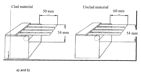
BRIEF DESCRIPTION OF THE DRAWINGS
Figure 1a shows a rig with mounted samples used for the sagging tests of clad
strip,
using a cantilever beam length of 50mm.
Figure lb shows a rig with mounted samples used for the sagging tests of
unclad strip,
using a cantilever beam length of 60mm.
Figure 2a shows the microstructure of material C after brazing from H24-temper
(left)
and 0-temper (right) after 1% pre-stretching prior to brazing.
Figure 2b shows the microstructure of material C after brazing from H24-temper
(left)
and 0-temper (right) after 3% pre-stretching prior to brazing.
DETAILED DESCRIPTION OF THE INVENTION
The object of the present invention is a method for producing aluminium strip,
which
after brazing have a relatively very high strength combined with very good
brazing
performance, described as a high sagging resistance and a very low
susceptibility to
liquid core penetration during brazing, as well as reasonably good forming
properties in
the as delivered strip condition. The sheets are intended for fin applications
in heat
exchangers produced by CAB brazing, but can also be produced by vacuum
brazing.
According to one aspect of the present invention, there is provided a strip
produced by:
a) casting a melt comprising:
0.3-1.5 weight-% Si,
5 0.5 weight-% Fe,
5. 0.3 weight-% Cu,
1.0-2.0 weight-% Mn,
5 0.5 weight-% Mg,
5 4.0 weight-% Zn,
5 0.5 weight-% Ni,
5 0.3 weight-% each of dispersoid forming elements from group IVb, Vb, or Vlb
of the
periodic table of elements, and
unavoidable impurity elements, each at most 0.05 weight-%, in a total amount
of at most
0.15 weight-%, the rest aluminium, so as to obtain an ingot;
CA 02607784 2013-05-02
4a
b) preheating the ingot at a temperature of less than 550 C so as to form
dispersoid
particles;
c) hot rolling to obtain a strip;
d) cold rolling the strip obtained in step c) with a total reduction of at
least 90% resulting
in a strip material having a first proof stress value;
e) followed by a heat treatment to the delivery temper with the purpose to
soften the strip
material by a tempering without any recrystallisation of the strip alloy, in
such a way that
a strip is obtained having a second proof stress value which is 10-50% lower
than the
first proof stress value obtained directly after cold rolling in step d) and
lying in the 0.2%
proof stress range of 100-200 MPa.
According to another aspect of the present invention, there is provided a
strip produced
by:
a) twin-roll strip casting a melt comprising:
0.3-1.5 weight-1)/o Si,
5 0.5 weight-% Fe,
5 0.3 weight-% Cu,
1.0-2.0 weight-% Mn,
5 0.5 weight-% Mg,
5 4.0 weight-% Zn,
5 0.3 weight-% each of dispersoid forming elements from group IVb, Vb, or Vlb
of the
periodic table of elements, and
unavoidable impurity elements, each at most 0.05 weight-%, in a total amount
of at most
0.15 weight-%, the rest aluminium;
b) cold rolling the as-cast strip to an intermediate gauge material;
c) annealing the intermediate gauge material, so as to form dispersoid
particles;
d) cold rolling the intermediate gauge material to a finstock material of
final gauge with a
rolling reduction of at least 60% resulting in a finstock material having a
first proof stress
value; and
e) heat treating the finstock material to the delivery temper with the purpose
to soften the
material by a tempering without any recrystallisation of the strip alloy, in
such a way that
a strip is obtained having a second proof stress value which is 10-50% lower
than the
first proof stress value obtained directly after cold rolling in step d) and
lying in the 0.2%
proof stress range of 100-200 MPa.
CA 02607784 2013-05-02
4b
According to a further aspect of the present invention, there is provided a
method of
producing a strip, comprising:
a) casting a melt containing:
0.3-1.5 weight-% Si,
50.5 weight-% Fe,
50.3 weight-% Cu,
1.0-2.0 weight-% Mn,
5Ø5 weight-% Mg,
54.0 weight-% Zn,
5 0.3 weight-% each of dispersoid forming elements from group IVb, Vb, or Vlb
of the
periodic table of elements, and
unavoidable impurity elements, each at most 0.05 weight-%, in a total amount
of at most
0.15 weight-%, the rest aluminium, so as to obtain an ingot;
b) preheating the resulting ingot at a temperature of less than 550 C so as to
form
dispersoid particles;
c) hot rolling to obtain a strip;
d) cold rolling the strip obtained in step c) with a total reduction of at
least 90% resulting
in a strip material having a first proof stress value;
e) followed by a heat treatment to the delivery temper with the purpose to
soften the strip
material by a tempering without any recrystallisation of the strip alloy, in
such a way that
a strip is obtained having a second proof stress value which is 10-50% lower
than the
first proof stress value obtained directly after cold rolling in step d) and
lying in the
absolute proof stress range of 100-200 MPa.
According to a further aspect of the present invention, there is provided a
method of
producing a strip, comprising:
a) twin-roll strip casting a melt comprising:
0.3-1.5 weight-% Si,
50.5 weight-% Fe, .
50.3 weight-% Cu,
1.0-2.0 weight-% Mn,
5. 0 . 5 weight-% Mg,
54.0 weight-% Zn,
5 0.3 weight-% each of dispersoid forming elements from group IVb, Vb, or Vlb
of the
periodic table of elements and
CA 02607784 2013-05-02
4c
unavoidable impurity elements, each at most 0.05 weight-%, in a total amount
of at most
0.15 weight-%, the rest aluminium;
b) cold rolling the as-cast strip to form an intermediate gauge material;
c) annealing the intermediate gauge sheet material so as to form dispersoid
particles;
d) cold rolling the intermediate gauge article to a finstock material of final
gauge with a
rolling reduction of at least 60% resulting in a finstock material having a
first proof stress
value; and
e) heat treating the finstock material to the delivery temper with the purpose
to soften the
material by a tempering without any recrystallisation of the strip alloy, in
such a way that
a strip is obtained having a second proof stress value which is 10-50% lower
than that
obtained directly after cold rolling in step d) and lying in the proof stress
range of 100-
200 MPa.
The object is achieved by the method according to the present invention for
producing
AlMn sheets in which a rolling slab is produced from a melt which contains (in
weight-
percent) 0.3-1.5% Si, 50.5% Fe, 50.3% Cu, 1.0-2.0% Mn, 50.5% Mg, 54.0% Zn,
50.3%
of each of elements from group 1Vb, Vb, or Vlb elements, the sum of these
elements
being 5Ø5%, and unavoidable impurity elements, whose individual amounts are
at most
0.05% and whose sum is at most 0.15%, as well as aluminium as the remainder in
which the rolling slab prior to hot rolling is preheated at a preheating
temperature of less
than 550 C, preferably between 400 and 520 C, more preferably between 450 and
520 C, especially more than 470 up to 520 C, to control the number and size of
dispersoid particles (particles precipitated from supersaturated solid
solution), whereafter
the preheated rolling slab is hot rolled into a hot strip. All amounts of
alloying elements
hereafter given are in weight percent. Normal total hot rolling height
reduction of the strip
thickness is >95%. The hot strip exit gauge is in the range from 2 to 10 mm.
The strip
may be annealed after hot rolling or at a cold rolled thickness above 0.5mm.
The strip is
thereafter cold rolled into a strip with a total reduction of at least 90%,
preferably above
95%, most preferably above 97.5% and the cold rolled strip is heat treated to
obtain a
proof stress value that is 50 - 90% of its proof stress value in the as cold
rolled condition
(not fully soft annealed) to a 0.2% proof stress in the range between 100 and
CA 02607784 2007-10-11
=
200 MPa, more preferably in the range 120-180 MPa, most preferably 140-180
MPa. The
strip material then has a microstructure comprising a number density of
particles in the range
between 1 and 20x106, preferably between 1.3 and 10x106, most preferably
between 1.4 and
7x10⁶particles/mm2the particles having an equivalent diameter in the range of
50-400 nm.
5 The majority of these fine particles are created during the preheating
prior to hot rolling. A
description on how the particle density was measured is described in example
1.
Alternatively, the same alloy composition can be cast by continuous casting
into a strip, e.g.
by twin-roll strip casting, such as described in EP1250468. The as-cast strip
is further rolled
to form an intermediate gauge article, which is then annealed, and once again
cold rolled with
a rolling reduction of at least 60%, preferably above 75%, so as to obtain a
finstock material
of final gauge, which has first proof stress value. The finstock material is
heat treated to the
delivery temper with the purpose to soften the material by a tempering without
any
recrystallisation of the strip alloy, in such a way that a strip is obtained
having a second proof
stress value which is 10-50% lower, preferably 15-40% lower, than that
obtained directly after
the second cold rolling, whereby the resulting 0.2% proof stress lies in the
range of 100-200
MPa, preferably 120-180 MPa, more preferably 120-160 MPa. The strip material
then has a
microstructure comprising particles having a diameter in the range of 50-400
nm with a
number density of particles in the range between 1.106 and 20.106, 1,3.106 and
10.106,
preferably between 1,4.106and T106 particles/mm2. The majority of the
particles have been
created during the intermediate annealing.
Typical thickness of the cold rolled finished strip is less than 0.2 mm,
preferably less than
0.15 mm, most preferably less than 0.10 mm. The material only has the desired
properties
for the tempered state, for example in the state H22, H24 or in the state H26
(strain
hardened, re-annealed to 1/4, 1/2 and 3/4 hardness respectively). The
annealing treatment is
performed as re-annealing in the coil or in a continuous annealing furnace
using a
temperature to be adjusted accordingly.
The present invention is based on a composition of the melt used to tailor the
microstructure
development during the complete processing to give the desired post braze
properties and
performance during brazing in combination with adequate delivery properties of
the strip. In
particular the high post braze strength combined with a good sagging
resistance and low
susceptibility to liquid core penetration during brazing, as well as a
relatively good formability
in the delivery condition prior to fin forming is the focus for this
invention. The post braze
0.2% proof stress value is at least 60 MPa, and normally about 70 MPa. The
sagging
resistance of the material is 535 mm, more preferably 530 mm, most preferably
525 mm,
when measured as defined in example 1 on a strip less than 0.1 mm in
thickness. No severe
liquid core penetration occurs during brazing. The formability measured as
fracture
CA 02607784 2007-10-11
6 =
elongation, A50õ, is normally above 3%. As the coil always is cut in rather
narrow strip before
delivery, all mechanical properties are measured and defined in the rolling
direction.
A high degree of deformation increases the driving force while a high number
of small
particles retard the driving pressure for recrystallisation. The driving force
increases with
increased rolling reduction, especially cold reduction, but will be decreased
by recovery
during the final temper annealing. The strength in the delivery condition for
this type of alloy
and processing is proportional to the driving force. The number of small
particles should be
controlled by the pre-heating to less than 550 C, preferably between 400 and
520 C, more
preferably between 450 and 520 C, and especially between 470 and 520 C prior
to hot rolling
in combination with mainly the chemical composition. The number density of
particles is
proportional to the retarding pressure hindering recrystallisation. It is of
uttermost importance
to control the driving force and the retarding pressure quantitatively to
achieve the good
material properties at the different stages mentioned above. Control of the
process within the
ranges claimed in this invention gives a high reproducibility of the material
properties.
Mn in dispersoid particles and in solid solution increases the post braze
strength.
Furthermore, Mn in a controlled number of particles is beneficial to control
the sagging
resistance and sensitivity to liquid core penetration as these particles
control the
recrystallisation process during braze heating leading to the formation of
large recrystallised
grains. The content of the melt provided according to the present invention of
at least 1.0 to
at most 2.0% supports the strength of the strip according to the present
invention. Optimized
properties may be reliably achieved if the Mn content is at least 1.3% and at
most 1.8%, even
more preferably if the Mn content is between 1.4 and 1.7%.
Fe has an adverse effect mainly as it increases the risk for formation of
large intermetallic
constituent particles formed during solidification. It then limits the amount
and use of Mn in
the material. It is therefore limited to 0.5%, preferably to 0.3%.
Si decreases the solubility of Mn and creates a high density of dispersoid
particles combined
with Mn. This promotes high strength and good sagging resistance. Some Si is
also in solid
solution. Both in solid solution and in dispersoid particles, Si adds to the
strength. Too high
level of Si increases the risk for liquid core penetration during brazing. The
Si content of the
core should be 0.3-1.5%, preferably 0.5-1.1%, most preferably 0.65-0.95%. For
material that
is to be braze clad, the Si content should be 0.3-1.5%, preferably 0.4-1.1%,
most preferably
0.45-0.9%, the contents of all other components being the same as for an
unclad material.
The strength and sagging resistance may be further improved by the addition of
group IVb,
Vb, or Vlb elements, or combinations of these elements, to the alloy according
to the present
invention, as some of these elements will add to the number density of fine
dispersoid
CA 02607784 2007-10-11
7
particles. The individual content of these dispersoid forming elements should
be lower than
0.3%, and the sum of these elements 50.5% to avoid formation of coarse
constituent
particles formed during solidification. Such particles have a negative
influence on the
formability and strength of the strip produced according to the present
invention. The content
of the group IVb, Vb, or Vlb elements should preferably be in the range 0.05-
0.2%.
Preferably 50.3% Zr is used as the dispersoid forming element from these
groups, preferably
in the range 0.05-0.2%, more preferably 0.1-0.2%. Furthermore, in combination
with Mn and
Fe, Cr may lead to very coarse constituent particles. Therefore, in the alloy
used according to
the present invention, if Cr is added the Mn content has to be reduced.
The content of Cu is limited to at most 0.3%, preferably below 0.1%, in the
alloy used
according to the present invention. Cu increases the strength, but also leads
to a positive
corrosion potential which is not desired in fin materials. A positive
corrosion potential restricts
the possibilities of combination with other materials in a brazed heat
exchanger. In addition,
the corrosion behaviour, particularly in regard to intercrystalline corrosion,
worsens with
increasing Cu content.
Small amounts of Mg may be added to an alloy used according to the present
invention as a
strength increasing element. However, since Mg has a very strong negative
influence on the
brazeability in CAB, the content of magnesium is restricted to at most 0.5%,
preferably to
below 0.3%, most preferably to below 0.1%. It furthermore increases the risk
for incipient
melting of the material at the brazing temperature.
Zn may be added to decrease the corrosion potential of the fin material and
thereby provide
the tubes with a cathodic protection by sacrificing the fins. By using an
adjustable Zn content
in the fin, the difference in corrosion potential between tubes and fins can
be chosen to an
adequate level for each application. The Zn content used is normally
restricted to 4.0% and is
more preferably between 0.5 and 2.8%.
The amount of Sn should preferably be kept below 0.009% to avoid problems at
rolling.
For brazing of the strip produced according to the present invention, it may
be favourable to
the mechanical strength if the strip is clad on one or both sides, using
cladding layer
thicknesses of 3% to 20% of the total thickness of the strip on each side. The
alloys
concerned may, for example, be typical brazing alloys based on Al-Si (Si 7-
13%), such as
AA4343, AA4045 or AA4047 , as well as typical protective claddings based on
commercially
pure Al alloys (AA1XXX, Si 0-0,5%) and the modifications of these alloys (Si
0,5-7% or Si
0,6-6,5%), such as Al alloys having a Si content of 1, 2, 3, 4, 5 or 6% Si..
The cladding is
preferably applied in this case by roll cladding.
CA 02607784 2007-10-11
8
EXAMPLES
Example 1
Two ingots of material Al and A2 with a composition of 0,8-0,9% Si, 0,2% Fe,
1,6% Mn,
0,11-0,12% Zr, 1,5-1,6% Zn and other elements each less than 0,05% were DC-
cast pre-
heated below 550 C and hot rolled with a total hot reduction of 99% prior to
cold rolling.
Material Al was directly cold rolled to final gauge and annealed at different
temperatures.
Some material was fully soft annealed to 0 temper, some was recovery annealed
to H24
temper and some was not annealed at all giving H18 temper. Material A2 was
recrystallisation annealed before final cold rolling to H14 temper. All
samples were exposed
to a heat treatment to simulate brazing at 600 C.
The properties are shown in Table I.
The sagging resistance was measured according to the following method: The
material is
mounted in a special rig as shown in Figure 1. Samples 15mm wide were cut
across the
rolling direction and at least 90 mm along the rolling direction. Four samples
were mounted in
the rig. The cantilever beam length was 60 mm, and the free end of the
cantilever was 54
mm above the surface of the measuring table.
The rigs were placed in the oven and the temperature was raised according to
the following
cycle:
20 C -> 400 C/25 min. + 4000C/5 min. + 400 C -> 600 C/13 min. + 6000C/10 min
The samples were removed immediately after the last soak at 600 C.
Temper Final cold Mechanical properties
reduction
Pre-braze Pre-braze Post-braze Sagging
Distance
Material A50mm R90.2 Gauge R0.2 Rm
[Vo] [MPa] [mm] [MPa] [MPa] (mm)
Al H18 ¨98 1.2 240 0.10 62 143 41
Al H24 1.3 193 0.10 63 150 32
Al 0 5.4 64 0.10 66 150 14
A2 H14 46 2.2 188 0.10 49 127 26
Table 1. Properties of materials Al and A2. The sagging resistance was
measured
using a cantilever beam length of 60 mm.
CA 02607784 2007-10-11
9 =
The results show that a much higher post braze strength is obtained with the
non-
interannealed 0, H24 and H18 tempers compared to the H14 delivery temper.
Example 2
Three ingots from the very same charge, with composition of 0,8% Si, 0,2% Fe,
1,6% Mn,
0,12% Zr, 1,6% Zn and other elements each less than 0,05%, were pre heated at
different
temperatures prior to hot rolling to improve the delivery formability and
sagging resistance
during brazing. The final temperatures and total heating times for the
different ingots were for
B1 ¨ 457 C/11hours, B2 - 490 C/15hours, B3-540 C/21hours. The materials were
hot rolled,
cold rolled and recovery annealed to H24 temper. The properties of 0.1 mm
final strip are
given in Table 2.
Materia Pre heating As delivery As delivery Sagging
Temp/total Rp0.2 [MPa] A5Omm rid distance
time [mm]
B1 457 C/11hours 184 3.8 22
B2 490 C/15hours 175 6.8 18
B3 540 C/21hours 197 4.4 30
Table 2. Properties measured for material B. The sagging resistance was
measured
using a cantilever beam length of 60 mm.
The results show that there is an optimum temperature and time for preheating
prior to hot
rolling to achieve the best combination of formability in as delivery temper
and sagging
resistance during brazing. A decrease of the delivery 0.2% proof strength from
197 MPa to
175 MPa significantly improves the sagging resistance during brazing.
Example 3
The effect of delivery temper was investigated on braze clad strip of a
material C with
following composition:
Core Mn=1.6%, Si=0.8%, Fe=0.2%, Zn=1.5%, Zr=0.11%, other elements each less
than
0.05%. Braze clad Si=7.7% , Fe=0.1%, other elements each less than 0.05%. The
material is
clad with 10% on each side. Cladding was carried out during hot rolling.
CA 02607784 2007-10-11
=
The material was DC-cast, followed by pre heating below 550 C, hot rolling to
4 mm and cold
rolling to 0.10 mm final thickness. The material in H14 condition was fully
soft annealed at
0.17 mm intermediate gauge. All samples in this example are taken from the
identical mother
coil. The different samples could be taken by splitting the coil in different
parts.
5 To measure the particle density of the material sections were cut in the
longitudinal, ND-RD,
plane of the strip. The sections were mechanically polished using Struers OP-S
suspension,
containing 0.04 pm colloidal silica, in the last preparation step. The area
cross-sections of the
particles were measured in a FEG-SEM, Philips XL30S, using an image analysis
system from
Oxford Instruments, IMQuant/X.
10 Images for the measurements were recorded in the backscatter mode using
the "in-lens"
detector in the microscope. The measurements were made at a magnification of
x40000
times (related to the SEM display). In order to minimize the information depth
and to get a
good spatial resolution in the backscatter image, a low acceleration voltage,
3 kV, was used.
Common grey level threshold was used to detect the particles. In order to
obtain a result that
is representative of the number and distribution of the particles in the
sample, the measured
image frames were spread over the cross section. Measurements were made on at
least
seven positions equally distributed over the thickness (ND) direction of the
strip sample. The
distance between each image frame in the longitudinal direction was at least
15 pm. More
than 1000 particles were measured. The area, A, of each particle is measured
and an
equivalent particle diameter is calculated as 4(4A/Tr).
The samples had prior to brazing a number density of particles within the size
range 50-400
nm of 2,3x10⁶ particles per mm2. The proof stress and elongation values prior
to brazing, the
sagging resistance and risk for liquid core penetration as well as the post
braze strength for
the different conditions are shown in Table 3. The post braze strength is
considerably lower
for the H14 (intermediately annealed and finally cold rolled) delivery
condition than the others.
The annealing, H24 and 0, improves the post braze strength compared to the
only cold rolled
H18 condition. The annealing significantly improves the sagging resistance and
further
improves the delivery formability, komm, as well as decreases the risk for
liquid core
penetration.
The H24 delivery condition gave significantly improved formability and better
sagging
resistance compared to the H14 delivery temper. The H24 condition gave much
better
sagging resistance, better resistance to liquid core penetration and a clearly
improved
delivery formability and post braze strength compared to the H18 condition. 0
temper
condition gave better delivery formability and sagging resistance than I-124
condition but is
CA 02607784 2007-10-11
11
not attractive due to handling problems of very soft and thin material prior
to brazing as well
as the risk for liquid core penetration after forming as described in Example
4.
Delivery As As Sagging Liquid core Post braze
delivery delivery distance
Temper penetratio Strength
RP0.2 A5Omm [(6/0] [mm] n [MPa]
[MPa]
H18 208 2.5 45 (max) Some 70
H24 163 5.3 16 No 77
0 61 10.4 11 No 78
H14 184 1.5 23 No 57
Table 3. Properties measured for material C. The sagging resistance was
measured
using a cantilever beam length of 50 mm.
Example 4
The 0 temper condition is not a suitable delivery temper as such soft and thin
strip causes
severe handling problems, both for strip producers and manufacturers of brazed
heat
exchangers. One of the problems is that the strip always will be slightly
stretched prior to
brazing. This can cause a poor brazing performance as the core then becomes
extremely
susceptible to liquid core penetration if delivered in 0 temper instead of H24
temper. A
material D with the following composition was used to show this:
Core Mn=1.6%, Si=0.8%, Fe=0.2%, Zn=1.5 /o, Zr=0.12%, other elements each less
than
0.05%.
Braze clad Si =7.5%, Fe =0.2%, other elements each less than 0.05%.
The material was clad on two sides with 10% braze clad on each side. Cladding
was carried
out during hot rolling.
The material was industrially produced according to the described invention to
a final
thickness of 0.07mm. Some material was temper annealed to H24 condition,
Rp0.2=164 MPa,
and some to fully soft 0 condition, Rp0.2=60MPa. Different amounts of
stretching of 0%, 1%,
3% and 5% was then applied to the samples prior to brazing.
The photographs in figure 2 show that severe liquid core penetration has
occurred during
brazing for the 0 temper but not for the H24 temper when the samples were pre-
stretched to
3%. Similar results were obtained for 5% pre-stretching. None of the delivery
tempers are
CA 02607784 2007-10-11
12
sensitive for liquid core penetration if the pre-stretching is 1% or less. As
pre-stretching to
more than 1% is likely to occur prior to brazing, the 0 temper condition is
not suitable.
Example 5
An alloy consisting of 1% Mn, 1% Si, 0,5% Fe, 0,09% Cu, 1% Zn was twin-roll
cast as a
5 mm thick strip, cold rolled to 1 mm, annealed to a soft condition, rolled to
0,10 mm
thickness and finally annealed for two hours at 260 C. The 0,2% proof stress
value, R02 was
130 MPa and the elongation, A50õ, was 4,4%. The post braze strength, R2, was
70 MPa,
and the ultimate strength, Rib 165 MPa. The sagging was only 9 mm, when
measured as
described in example 1.