Note: Descriptions are shown in the official language in which they were submitted.
CA 02607997 2007-11-07
PACKAGE FOR CHANGING A STORED PRODUCT TEMPERATURE
PRIOR TO THE OPENING THEREOF
Field of the invention
The invention relates the food industry, more specifically to packages for
such
objects that should be heated up or cooled down to a required temperature
prior to
consumption or use.
Background of the Invention
Different designs of packages are known from the prior art, said packages
being
provided with means which allow the heating of a stored product up to a
predetermined
temperature as a result of the course of the exothermic reaction, or the
cooling of a stored
product down to a predetermined temperature as a result of the course of the
endothermic
reaction.
Thus, a package is known for changing a stored product temperature prior to
the
opening thereof, said package comprising: a cylindrical case with a heat
insulating coating at
an external lateral surface and with a bottom having a central portion
extending into the case;
a sealed container for the stored product, said container being coaxially
installed within the
case closely to its bottom central portion extending into the case to form an
annular cavity
between its external lateral surface and an internal lateral surface of the
case, wherein a lower
portion of the annular cavity is filled with a solid reagent while a chamber
of an elastic
material, for example plastic, is located in an upper portion of the annular
cavity and is filled
with a liquid reagent. The annular cavity is closed at the top by an annular
lid hermetically
connected along its external contour to the case and along its internal
contour - to the
container, wherein an annular strip of an elastic material is placed between
the annular lid
and the elastic material chamber. The annular lid is provided with two dents
to perforate it
while the upper portion of the container is provided with a closure (see US-A-
5,542,418,
1996).
The basic disadvantage of said package for changing prior to the opening
thereof
consists in that it does not allow high effectiveness of using heat evolved as
a result of the
exothermic reaction because the heat supply to the container with the stored
product takes
place only via the lateral surface of the container and is accompanied with a
large heat loss
via the case bottom where the heat insulation is absent. Further, when gases
evolved during
CA 02607997 2007-11-07
2
the exothermic reaction ascend to the top of the annular cavity, they form a
gas space
between reagents, said gas space decelerating the process of mixing the
reagents. This results
in reduction of a maximum reaction temperature. It should be also noted that
the presence of
the elastic material strip does not exclude the ability of the high-
temperature products of the
exothermic reaction to arrive at the upper surface of the container, which
generates additional
problems and inconveniences in use of the package.
A package is also known for changing a stored product temperature prior to the
opening thereof, said package being taken as a prototype and comprising: an
upper
detachable cap, a heat insulating body and a thermal module with an activator
including a
piercing member fastened on a central portion of a bottom of a thermal module
case, said
central portion being formed flexible and convex outwardly. Arranged in a
thermal module
case are a stored product container hermetically connected thereto around an
entire perimeter
of own upper portion, a solid reagent, and a liquid reagent storage section
comprising a
closed cylindrical compartment with a protrusion in its upper portion, said
protrusion
providing the fixation of said section relative to a bottom of the stored
product container.
Further, the closed compartment in its lower portion is provided with an
annular flange and
radially arranged channels. The closed compartment is filled with a liquid
reagent, is formed
of a material capable to be pierced, and is installed to interact with a tip
of the activator of the
thermal module in actuation thereof. To this end, the annular flange of said
section is
arranged at an internal surface of the bottom of the thermal module case while
a bottom
portion arranged oppositely to the tip of the piercing member is concaved into
the closed
compartment to form a cavity in communication via said radial channels with a
cell in the
cavity of the thermal module case filled with the solid reagent (Patent US-A-
3,970,068,
1976, Figs. 8, 9).
The prototype package for changing a stored product temperature prior to the
opening
thereof has disadvantages as follows:
- it is inconvenient in use because the actuation of the thermal module
activator
requires, first, to turn the package upside-down, second, to remove the bottom
safety cover,
third, to destroy (to pierce) the bottom of the closed cylindrical compartment
filled with the
liquid reagent with the piercing member by applying a user's force in the
axial direction to
the convex area in the bottom of the thermal module case;
- it is characterized by significant heat loss in the course of the exothermic
reaction
because the reagents are mixed near the bottom of the thermal module case, in
other words,
at a place where the heat insulation is absent;
CA 02607997 2007-11-07
3
- the liquid reagent section has a complicated design (there are the flange
and the
radial channels) which gives rise to the package cost.
Further, the prior art package does not comprise means to provide reduction in
a peak
value of the gas-vapor mixture in the cavity of the thermal module case in the
course of the
endothermic reaction. In other words, the increased requirements in part of
the mechanical
strength are imposed upon a material of the stored product container and the
thermal module
case integrated therewith.
Summary of the Invention
The present invention is aimed at solution of the technical problem to improve
the
convenience in use of a package for changing a stored product temperature
prior to the
opening thereof at simultaneous increase of effectiveness of using the heat
effect of a reagent
reaction due to reduction in heat exchange with environment and also lowering
of the
requirements to the strength parameters of a stored product container and a
thermal module
case by lowering a peak value of a gas-vapor medium pressure in the course of
the reaction.
The problem of the invention is solved by that, in a package for changing a
stored
product temperature prior to the opening thereof, said package comprising a
thermal module
placed in a heat insulating body and having an activator including a piercing
member with a
tip, wherein arranged in a thermal module case are a stored product container
hermetically
connected thereto around an entire perimeter of own upper portion as well as a
solid reagent
and a closed compartment formed of a material capable to be pierced,
containing a liquid
reagent and installed to interact with the tip of the piercing member of the
activator of the
thermal module when the latter is driven, according to the invention, there
are recesses
formed at equal angular distances relative to each other in a sidewall of the
thermal module
case at least oppositely to the closed compartment arranged therein, wherein
an internal
surface area of each recess bottom is arranged at a minimum gap or closely to
the closed
compartment, the heat insulating body is formed with a bottom and a sidewall
flexed at
application of a radially directed external load by a user, the thermal module
activator
additionally comprises a holder having an annular shape and installed
coaxially with the
thermal module case to sense the external load when the sidewall of the heat
insulation case
flexes and to move the piercing member installed thereon under action of said
load in a radial
direction, the tip of said piercing member being arranged in its respective
recess formed in
the sidewall of the thermal module case oppositely of the closed comparhnent,
and a distance
between the tip of the piercing member and the closed compartment with the
liquid reagent is
CA 02607997 2007-11-07
4
smaller than a maximum flexure value of the sidewall of the heat insulating
body.
The problem of the invention is additionally solved by that:
- the thermal module further comprises a protective gas-watertight housing
hermetically connected around a perimeter of own upper portion to the thermal
module case
and the stored product container, said protective gas-watertight housing being
arranged
between the thermal module case and the heat insulating body;
- the protective gas-watertight housing is arranged closely to an internal
surface of the
heat insulating body;
- the protective gas-watertight housing is arranged with a gap relative to the
internal
surface of the heat insulating body;
- the holder of the thermal module activator is annularly shaped with at least
one
resiliently deformable area having a weakened mechanical strength;
- the holder is fastened at the internal surface of the sidewall of the heat
insulating
body;
- the holder is fastened at an internal surface of the protective gas-
watertight housing;
- the holder of the thermal module activator is formed as an open ring and is
integrated with piercing members arranged oppositely to each other and having
an elongated
triangular shape;
- the holder is fastened at the internal surface of the sidewall of the heat
insulating
body;
- the holder is fastened at an internal surface of the protective gas-
watertight housing;
- the thermal module case is formed with a cylindrical lower portion having
said
recesses arranged in the sidewall thereof, the holder of the thermal module
activator is
formed as an open ring of a resiliently deformable material with two identical
arched pushers
fastened as cantilevers and arranged at its external cylindrical surface, and
with identical
protrusions arranged uniformly around a circumference of an internal
cylindrical surface of
the open ring, a number of said protrusions being equal to a number of
recesses in the lower
cylindrical portion of the thermal module case, the holder has two through
openings
positioned radially and coaxially and each passing via a respectively
protrusion of a pair of
protrusions arranged oppositely to each other, each of the two piercing
members is formed as
a thin metal rod pointed from one side and is located to perform a sliding
longitudinal
displacement in a through opening corresponding thereto and formed in the
holder, the tips
of the piercing members are arranged oppositely to each other on both sides of
the thermal
module case and closely to a bottom of a respective recess, wherein a length
of the piercing
CA 02607997 2007-11-07
members is greater than a length of said through openings in the holder at
least by a value of
a distance between their tips and the closed compartment while free ends of
the arched
pushers are arranged to interact with non-pointed faces of the piercing
members protruding
-beyond the open ring when said free ends flex towards the open ring, the open
ring is
arranged outwardly of the lower portion of the thermal module case, wherein
the protrusions
at the internal surface of said ring are arranged in respective recesses in
the sidewall of the
lower portion of the thermal module case and are pressed to their bottom
surfaces by forces
of the resilient strain of the open ring;
- the thermal module further comprises a casing head in the form of a
cylindrical cup
spring-loaded from the side of its bottom relative to the bottom of the heat
insulating body
and tightly encompassing the lower portion of the thermal module case with the
possibility of
axial movement relative to said lower portion, a radial through opening is
formed near the
bottom of the lower portion of the thermal module case, wherein a corrugation
open only
from below is arranged on a sidewall of the casing head oppositely to said
radial through
opening and forms a channel with the external surface of the sidewall of the
thermal module
case while a cavity of the casing head communicates with a cavity of thermal
module via
said channel and said radial opening, wherein at least one pair of openings
are formed in
sidewalls of the casing head and the lower portion of the thermal module and
are arranged to
provide their coincidence with each other at the lowermost position of the
casing head;
- the recesses in the sidewall of the thermal module case are formed as
grooves
arranged along a generatrix of said sidewall;
- the recesses in the form of grooves are shaped as a conical surface area
having a
vertex facing upwardly;
- a bottom of at least one recess has a through opening formed therein and
covered by
a plate of a porous material from the external side of the thermal module
case;
- the recesses in the sidewall of the thermal module case are formed as holes;
- the recesses formed as holes have a shape of a surface of revolution of a
second-
order curve arc;
- the upper portion of the thermal module case has an least one through
opening
formed therein and covered by a plate of a porous material from the external
side of the
thermal module case;
- the thermal module further comprises a mount fastened from the external side
of the
stored product container, and the closed compartment is placed in the mount;
- the holder of the thermal module activator is formed as a ring with two
posts
CA 02607997 2007-11-07
6
arranged oppositely to each other in a diametric plane of the package, said
plane being a
symmetry plane of the two recesses arranged oppositely to each other in the
sidewall of the
thermal module case, wherein each post includes two flexible rods parallel to
each other and
tilted away from a package axis, lower ends of said rods being fastened on the
ring and upper
ends of the rods being connected to each other by a crosspiece parallel to a
ring plane and
having a piercing member fixedly fastened therein;
- the heat insulated body is provided with an opening in the bottom thereof;
- the stored product container is provided at the top with a discoverable
closure of a
sheet material having an external surface area with a thermal paint applied
thereto and having
an irreversible color variation in heating up to a respective temperature;
- containers of gas-water-permeable material are placed between the heat
insulating
body and the thermal module case and filled with a substance that sorbs steam
and gases
evolved when the reagents react with each other;
- at least containers of a gas-water-permeable material are placed between the
protective gas-watertight housing and the thermal module case and filled with
a substance
that sorbs steam and gases evolved when the reagents react with each other.
The advantage of the inventive package for changing a stored product
temperature
prior the opening thereof over the prototype consists in that an embodiment of
the liquid
reagent section without a flange and radial channels and simply in the form of
the closed
compartment allows not only simplification of the package design and therefore
reduction of
its cost but also placement of the thermal module activator not below but from
the side of the
closed comparhnent. As a result, the use of the packages becomes more
convenient because
it is not necessary now to turn it upside-down when the thermal module is
driven. An
embodiment of the thermal module activator to be annularly-shaped, installed
coaxially with
the thermal module case and capable of sensing an external load when the
sidewall of the
heat insulating body flexes and of displacing the piercing members installed
on the holder in
a radial direction when they are subjected to said external load, the tips of
said members
being in the vicinity of the closed compartment with the liquid reagent due to
presence of
recesses in the sidewall, makes it possible to drive the thermal module in a
very simple
manner, exactly, by flexing with hand fingers from one or two (depending upon
a number of
piercing members fastened on the holder) oppositely arranged sides of the
sidewall of the
heat insulating body for several millimeters (2 to 4 mm on average, as
experiments have
shown). At the same time, the recesses in the sidewall of the thermal module
case, arranged
at least oppositely to the closed compartment arranged within the thermal
module case,
CA 02607997 2007-11-07
7
provide not only the possibility to drive the thermal module by small flexure
of the sidewall
of the heat insulating body but also to fix a position of the closed
compartment with the
liquid reagent when the piercing members act thereto.
An embodiment of the heat insulating body with the bottom makes -it possible
to
decrease significantly heat exchange in a reaction zone with environment
accompanied with
a heat effect (heat evolution or absorption). This allows improvement in
effectiveness of
using the heat effect of the reacting reagents and therefore reduction in
consumption thereof
to obtain a required change of a stored product temperature.
Use of the protective gas-watertight housing makes in possible to extend the
range of
materials used to manufacture the heat insulating body.
The disclosed modifications of embodying the ring-shaped holder of the thermal
module activator illustrate the possibility to fasten it on both the heat
insulating body and the
protective gas-watertight housing or the thermal module case to obtain the
expected result -
convenient use of the package - in any case.
The presence of the through openings in the side surface (in its upper
portion) of the
thermal module case, said openings being covered by plates of a porous
material from the
external side of the thermal module case, and also the presence of containers
with sorbents
allows essential decrease of a peak pressure value in the reaction zone and
therefore lowering
of the requirements to the strength parameters of the thermal module case, the
heat insulating
body and the protective gas-watertight housing.
Other advantages of the inventive package will become fully apparent from the
following description.
The invention will no be described with reference to embodiments thereof that
are not
solely possible but clearly demonstrate the possibility to accomplish the
required technical
result by said combination of essential features.
Brief Description of Drawings
Fig. 1 shows a front cross-sectional view of a package for changing a stored
product
temperature prior to the opening thereof;
Fig. 2 shows a bottom view of a thermal module case;
Fig. 3 shows a plane view of a holder;
Fig. 4 shows a cross section taken along line A-A in Fig. 3;
Fig. 5 shows a cross section taken along line B-B in Fig. 1;
Fig. 6 shows the same cross section after application of an external load P;
CA 02607997 2007-11-07
8
Fig. 7 shows embodiment of a holder crosspiece;
Fig. 8 shows another shows embodiment of the holder crosspiece;
Fig. 9 shows an embodiment of fastening an activator on a heat insulating
body;
Fig. 10 shows the first modification of the inventive package;
Fig. 11 shows a cross section taken along line C-C in Fig. 10;
Fig. 12 shows the second modification of the inventive package;
Fig. 13 shows an embodiment of hermetically sealed connection of a stored
product
container with a case and a protective housing of a thermal module;
Fig. 14 shows a plane view of the holder;
Fig. 15 shows a front view of the same;
Figs. 16 and 17 show inserts for the holder of Fig. 14;
Fig. 18 shows the third modification of the inventive package; and
Fig. 19 shows a cross section taken along line D-D in Fig. 18, wherein upper
crosspieces are not hatched.
Disclosure of the Invention
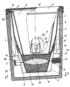
A package for changing a stored product temperature prior to the opening
thereof
comprises a heat insulating body with a detachable cap 2, a thermal module 3
which is
placed within the heat insulating body 1(preferably coaxially therewith), a
stored product
container 4 as well as an activator of the thermal module 3, said activator
including a holder
and at least one piercing member 6 (Fig. 1).
The heat insulating body 1 is formed as a cup having a flat or concave bottom
7 of a
moisture-gas-watertight, lightweight, shock- and flexure-proof material of low
heat
conduction and thermal stability at a temperature not lower than 200 C, for
example,
foamed polystyrene. A sidewall of the heat insulating body 1 can have any
shape -
cylindrical, conical, barreled, and so on, - but should be capable of flexing,
preferably
resiliently, when a user applies an external load in a radial direction
thereto.
To make the package more convenient in use, it is possible to provide the heat
insulating body 1 with a lateral handle, particularly a detachable handle (not
shown in the
drawings).
The thermal module 3 includes a thermal module case 8 having a closed
(hermetically sealed) compartment 9 arranged in a cavity thereof and designed
to place a
liquid reagent 10, for example water, and a solid reagent 11 (in the form of
granules of a
CA 02607997 2007-11-07
9
powder) therein
In the preferred embodiment of the invention, the thermal module case 8 is
axially
symmetrical relative to a package axis 12 and is in the form of a hollow
truncated cone with
a smaller base facing downwardly and being the bottom of the thermal module
case 8.
Principally, the thermal module case can have other shape as well, for
example, a shape of a
right circular cylinder as that in the prototype. An annular bead 13 is formed
at an external
surface of the thermal module case 8 and is arranged flush with an upper end
face of a
sidewall of the thermal module case 8 (in other words, flush with a major base
of the
truncated cone, see Figs. I and 2). Recesses 14 are formed as grooves in the
sidewall of the
thermal module case 8 and are arranged along a generatrix of said wall at
equal angular
distances from each other (in other words, uniformly along a circumference),
said recesses
being shaped (in the preferred embodiment) as an area of a conical surface
(that has a base
15 shown by dashed line in Fig. 2) with an apex facing upwardly and an axis 16
parallel to
the package axis 12. At the same time, a length of the recesses 14 is at least
3% less than a
length of the generatrix of the external side surface of the thermal module
case 8. It should be
noted here that the recesses 14 should be formed at least in areas of the
sidewall of the
thermal module case 8, arranged oppositely to the closed compartment 9,
wherein the
recesses 14 formed as grooves can be formed as areas of any (circular,
parabolic, and so on)
surface having an axis arranged at an acute angle to the axis 12, said angle
being higher than
a half angle at vertex of the conical sidewall of the thermal module case 8.
Preferably, a number of the recesses 8 in the form of grooves should be even:
4, 6.
The thermal module case 8 can be formed of polyethylene, processed
polyethylene
(PPE) as well as aluminum used in food industry. In case if the thermal module
case 8 is
formed of a polymeric material, it is expedient to clad at least an internal
surface thereof with
a foil.
The closed compartment 9 is formed of a film polymeric material capable to be
pierced, for example polyethylene, and is placed within the cavity of the
thermal module case
8 to provide a minimum gap between areas of an external surface thereof and
corresponding
areas of internal surfaces of bottoms in all recesses 14 (in preferable
embodiments, closely
thereto). In other words, with said even (4, 6) number of the recesses 14,
fixation of the
closed compartment 9 filled with the liquid reagent 10 is provided in the
transverse direction
when radially directed forces destroying walls of the compartment 9 act to
said compartment.
In the preferred embodiment, the upper portion of the sidewall of the thermal
module case 8
has at least one through opening 17 of 3 to 10 mm in diameter formed therein.
At the same
CA 02607997 2007-11-07
time, the through openings 17 are covered by respective plates 18 preferably
of a paper
having a sufficiently high density (a density not higher than 60 g/mZ) from
outside of the
sidewall of the thermal module case 8. Containers 19 (bags or pouches) of a
gas-permeable
material filled with a substance (active coal, silica gel, and so on) that
sorbs vapors and gases
evolved in the reaction of the reagents 10 and 11 with each other are placed
oppositely to
each through opening 9 in a cavity between the heat insulating body 1 and the
thermal
module case 8, for example, are glued to the internal surface of the sidewall
of the heat
insulating body 1. In a preferred embodiment (Figs. 1 and 2), the through
openings 17 are
formed in bottoms of the recesses 14 in the form of grooves, which allows
decrease in a
distance between the sidewalls of the heat insulating body 1 and the thermal
module case 8
and therefore increase in a fraction of a useful volume in the cavity of the
heat insulating
body 1.
In the preferred embodiment, the stored product container 4 is in the form of
a hollow
truncated cone having a major base that faces upwardly and a flange 20 formed
around a
perimeter of said base. The container 4 is placed in the cavity of the thermal
module case 8,
wherein its flange 20 is supported by an end face of the upper portion of the
thermal module
case 8 while edges of the flange 20 are rolled around the annular bead 13.
Thus, the container
4 is hermetically connected to the upper portion of the sidewall of the
thermal module case 8
throughout the perimeter of the major base. The closed compartment 9 is either
placed
closely to the bottom of the external surface of the container 4 or separated
therefrom by a
layer of the reagent 11.
The thermal module case 8 having the cavity where the reagent 11 and the
closed
comparhnent 9 with the reagent 10 as well as the container 4 hermetically
connected to the
upper portion of the thermal module case 8 are placed is installed within the
heat insulating
body 1 and is fixed thereto, for example, by placing the flange 20 rolled
around the annular
bead 13 in a respective annular groove formed in the upper portion of the
internal surface of
the heat insulating body 1(Fig. 1).
The holder 5 (Figs. 1, 3 and 4) is annular-shaped with at least one
resiliently
deformed area of a weaken mechanical strength, for example with thin straight-
line
crosspieces 21 and protrusions 22 facing inwardly (to the axis 12), wherein a
number of said
protrusions is equal to a number (preferably two) of the piercing members 6
formed, for
example, as thin (0.5 to 2.0 mm in diameter) steel rods (needles) having a tip
(pointed) from
one side. Each piercing member 6 is placed in a respective slot formed in a
surface of a
respective protrusion 22 and is fixed (stationary fastened) using a respective
patch piece 23
CA 02607997 2007-11-07
11
with fixing protrusions 24 that are inserted into their respective openings 25
formed in each
protrusion 22. The protrusion 22 are arranged oppositely to each other and
oppositely to a
respective recess 14 in the thermal module case 8 (Figs. 1, 3, 5 and 6),
wherein the piercing
members 6 are arranged oppositely to the closed cavity 9 along a straight line
passing via the
package axis 12 and corresponding to a direction of applying an external load
P (Fig. 6).
Principally, the piercing members 6 can be fastened on the holder having no
protrusions 22.
In particular, the piercing members 6 can be simply pressed into the material
of the holder in
molding thereof. Arched crosspieces 21.1 or V-shaped crosspieces 21.2 (Fig. 8)
can be used
instead of the crosspieces 21. The crosspieces 21.1 or 21.2 are either
integral with other
members of the holder 5 (Figs. 3 and 7) or formed as respective inserts of
other material, for
example, having a less mechanical strength (Fig. 8).
The holder 5 can be structurally embodied in other manner, for example, as a
hoop
having a limited external and/or internal surface.
The activator of the thermal module 3 (Fig. 1) is fastened at the internal
surface of the
sidewall of the heat insulating body 1 in such a manner that ends of the
piercing members are
located oppositely (and preferably touch) external surface areas of the
recesses 14
corresponding thereto, wherein said internal surface areas thereof are located
oppositely to
the external surface areas while external surface areas of the closed
compartment 9 are
located at a minimum gap or closely to said internal surface areas of the
recesses. In other
words, the tips of the piercing members 6 are arranged oppositely to the
closed compartment
9 and at a distance that is smaller than a maximum flexure value of the
sidewall of the heat
insulating body 1. To fasten the activator, a turned annular groove 26 is
formed at the
internal conical surface of the sidewall of the heat insulating body 1 and has
a diameter that
provides a required interference fit of the holder 5. If the heat insulating
body 1 is provided
with a sidewall having a cylindrical shape of the internal surface, fixation
of the holder 5
within the cavity of the heat insulating body 1 is provided by making an
annular bead or
support ribs 27 arranged uniformly over a circumference and along the
generatrix of the
internal surface (Fig. 9). In this case, slots 28 corresponding to the support
ribs 27 are formed
on the external surface of the holder 7 while the required interference fit of
the holder 5
(being resiliently deformable due to presence of the crosspieces 21.1 and
21.2) is provided by
selecting an appropriate ratio between the diameter of the holder 5 and the
diameter of he
internal surface of the heat insulating body 1.
However, the embodiments of fastening the thermal module activator on the heat
insulating body 1, as described above, are not exhaustive for the disclosed
technical solution
CA 02607997 2007-11-07
12
that allows fastening of the activator on other package components, for
example, on the
thermal module case. thus, the embodiment of the package for changing a stored
product
temperature prior to opening thereof, shown in Figs. 10 and 11, a heat
insulating body 1.1 is
made with a cylindrical sidewall being a truncated cone in the lower portion
to provide
reduction in the thickness of the material in the heat insulating body 1.1
within a zone where
its sidewall mates a bottom 7.1 where a blind opening 29 is formed.
A case of a thermal module 3.1 is axially symmetrical relative to the package
axis 12
and includes an upper portion 30 and a lower portion 31 preferably integrated
with each
other. The upper portion 30 of the case of the thermal module 3.1 and is in
the form of a
hollow truncated cone with a major base facing upwardly and an annular bead
13.1 designed
(similarly to that described above) to provide a hermetically sealed
connection (particularly,
by rolling) of the thermal module case with the stored product container 4.
The lower portion
31 is in the form of a cylinder with a bottom 32 and mates a smaller base of
the truncated
cone of the upper portion 30 from the top. At least two (preferably four, six)
recesses 14.1
formed as holes, arranged uniformly over a circumference, and preferably
having a shape of
a surface of revolution of a second-order curve arc, for example, an arc of a
circle, are
formed in the sidewall of the lower portion 31. At the same time (similarly to
the
embodiment of the recesses 14 formed as grooves and described above), the
closed
compartment 9 with the liquid reagent 10 is placed within the cavity of the
lower portion 31
oppositely to the recesses 14.1 (and preferably closely thereto) and allows a
minimum gap
between the external surface areas of said lower portion and respective
internal surface areas
of all recesses 14.1. The thermal module 3.1 further comprises a casing head
33 in the form
of a cylindrical cup tightly encompassing the lower portion of the case, being
capable of
moving relatively thereto and spring-loaded from the side of its bottom, for
example, by a
four-lobe spring 34 installed in the opening 29. A radial through opening 35
is formed near
the bottom 32 of the lower portion 31, wherein a corrugation 36 open only from
below is
arranged on a sidewall (along a generatrix thereof) of the casing head 33
oppositely to said
radial through opening and forms a channel with the external surface of the
lower portion 31
while a cavity of the casing head 33 communicates with a cavity of the thermal
module 3.1
via said channel and then via the opening 35. Furthermore, at least one pair
of openings 37
and 38 are formed in sidewalls of the casing head of the lower portion 31 of
the case of the
thermal module 3.1 and the casing head 33 and are arranged to provide their
coincidence
with each other at the lowermost position of the casing head 33. The stored
product container
4 is provided at the top with a discoverable closure 39, for example of
aluminum foil, with a
CA 02607997 2007-11-07
13
tab 40 for convenient removal thereof prior to use of a product present in the
container 4. An
activator of the thermal module 3.1 comprises a holder 5.1 and two piercing
member 6 that
are formed as thin steel rods (having a diameter of 0.5 to 2.0 mm) having a
tip (pointed) from
one - side, as described above. The holder 5.1 of a resiliently deformable
material,
advantageously a plastic material, is formed as a open (split) ring with two
identical arched
pushers 41 fastened as cantilevers and arranged at its external cylindrical
surface, and with
identical protrusions 42 arranged uniformly around a circumference of an
internal cylindrical
surface of the open ring, a number of said protrusions being equal to a number
of recesses
14.1. The holder 5.1 has two through openings positioned radially and
coaxially and each
passing via a respectively protrusion 42 of a pair of protrusions 42 arranged
oppositely to
each other. Each piercing member 6 is located to perform a sliding
longitudinal displacement
in a through opening corresponding thereto and formed in the holder 5.1, the
tips of the
piercing members 6 are arranged oppositely to each other and on both sides of
the lower
portion 31. A length of the piercing members is greater than a length of said
through radially-
positioned openings at least by a value of a distance between their tips. In a
preferred
embodiment of the invention, the arched pushers are arranged equidistantly
relative to the
external cylindrical surface of the open ring and are capable (when subjected
to forces
directed radially to an axis of the open ring) to interact at their non-
fastened end faces with
non-pointed faces of the piercing members 6 protruding beyond the open ring.
In a preferred
embodiment of the inventions, the arched pushers are rotated for 180 relative
to each other.
The activator of the thermal module 3.1 is place outside of the lower portion
31 of the case,
wherein the protrusion 42 of the holder 5.1 are arranged in respective
recesses 14.1 and
pressed to their bottom surfaces by forces of the resilient strain of the open
ring, while the
tips of the piercing members are arranged closely to surfaces of respective
recesses 14.1.
As noted above, the materials of the heat insulating body 1 and 1.1 should be
moisture-gas-watertight, lightweight material of sufficient thermal stability
and low heat
conduction. At the same time, to provide a value of a flexure, in other words,
a radial strain
of the sidewall of the heat insulating body, necessary for the thermal module
activator to
operate, a thickness of the sidewall itself must not be large because increase
in the thickness
will inevitably lead to increase in the force applied by a user to drive the
thermal module an
therefore to creation of additional inconveniences in use of the package. The
offered
embodiment of the thermal module with the protective has-watertight housing as
well as
other aspects of the present invention will now be explained below in
conjunction with Figs.
CA 02607997 2007-11-07
14
12 to 19.
A package for changing a stored product temperature prior to the opening
thereof
(Fig. 12) comprises a heat insulating cylindrical body 1.2 with an turned
annular groove 43
from the side of a bottom 7.2, a length of said turned annular groove being
1.05 to 1.5 times
larger than a thickness of the bottom 7.2. During transportation and storage,
a safety collar
43.1 shown in Fig. 12 by dashed line is removably installed in the turned
groove 43.
A thermal module case 8.1 is in the form of a hollow truncated cone with a
smaller
base facing downwardly and being the bottom of the thermal module case 8.1. An
annular
bead 13 is formed at an external surface of the thermal module case 8.1 and is
arranged flush
with an upper end face of a sidewall of said case. One or two recesses 14.1
(according to a
number of piercing members 6.1) are formed as holes preferably having a shape
of a surface
of revolution of a second-order curve arc on the sidewall (the conical wall)
of the thermal
module case 8.1. There are through openings 17 of 3 to 10 mm in diameter
formed in the
upper portion of the sidewall of the thermal module case 8.1, said openings 17
being covered
by respective plates 18 preferably of a paper having a density not higher than
60 g/m2 from
outside of the sidewall of the thermal module case 8.1.
A stored product container 4 is placed in the cavity of the thermal module
case 8.1
and (similarly to that described above) is in the form of a hollow truncated
cone having a
major base that faces upwardly and a flange 20 formed around a perimeter of
said base. A
smaller base of the truncated cone is a bottom of the container 4, and there
is a mount 44 fit
outside of said bottom and designed for the closed compartment 9 with the
liquid reagent 10.
The mount 44 is in the form of "a squirrel cage," exactly, in the form of two
annular
members, that is, a higher annular member 45 with a turned conical groove 46
for an
interference fit of the mount 44 onto the container 4, and a lower annular
member 47, said
members being connected between each other by vertical crossbars 48 arranged
along
circumferences of the annular members 45 and 47. The mount 44 can be ether a
monolith of
polymeric material or made of separate parts connected to each other by known
means. The
mount 44 provides fixation of a position of the closed compartment 9 relative
to the thermal
module case 8.1 in both axial (towards the axis 12) and radial directions not
only during
transportation of the package but also in the course of driving the thermal
module as a result
of which the closed compartment 9 is destructed in interaction with the
piercing members 6.1
and then the reagents 10 and 11 react with each other.
To provide convenient use of the package, the thermal module comprises a
protective
gas-waterproof housing 49 arranged between the heat insulating body 1.2 and
the thermal
CA 02607997 2007-11-07
module housing 8.1. The protective gas-waterproof housing 49 is in the form a
cylindrical
cup having a bottom. Aluminum, polyethylene, etc., can be used as a material
for
manufacturing the protective gas-waterproof housing 49. In case of using
polymeric
materials, an intemal surface of the protective gas-waterproof housing 49 is
preferably foiled.
At its upper portion, the protective gas-waterproof housing 49 is-hermetically
connected to
the flange 20, for example, is rolled (Fig. 12).
Fig. 13 shows another embodiment of the hermetically sealed connection of the
stored product container 4 to the thermal module case 8.1 and to the
protective has-watertight
housing 49 that in the present embodiment has an annular bead 50 made flush
with the upper
end on the external surface of side wall, In this case, edges of the flange 20
are rolled along
the beads 13 and 50 arranged closely. Principally the hermetically sealed
connection of the
stored product container 4, the thermal module case 8.1 and its protective has-
watertight
housing 49 is possible by means of gluing, thermal welding, brazing as well as
other means
and methods known in the food industry. In a preferred embodiment of the
invention, a layer
51 of a gas-vapor-sorption material is placed on an inner surface of the
sidewall of the
protected gas-watertight housing 49. The layer 51 is placed oppositely to the
openings 17,
wherein containers 19 of a gas-permeable material are additionally placed on
the bottom of
the protected gas-watertight housing 49, said container being filed with a
substance that
similarly to a material of the layer 51 sorbs vapors and gases evolved when
the reagents 10
and 11 react with each other. The thermal module activator consists of an
annular holder 5.2
formed of a resiliently deformable material and integrated with the piercing
members 6.1 of
the ring-shaped holder 5.2 (Figs. 14 and 15). The piercing members 6.1 have an
elongated
triangular shape and are formed by pressing out from an original solid tape
material of the
holder 5.2.
The holder 5.2 is in the form of either an open ring (Figs. 14 and 15) or two
identical
semi-rings 52 and 53 made of a resiliently deformable metal tape and connected
between
each other by V-shaped or arc-shaped inserts 54 and 54.1 (Figs. 16 and 17),
respectively. The
thermal module activator is placed at the internal surface of the sidewall of
he protective gas-
watertight housing 49 between two annular folds 55, wherein the piercing
members 6.1 abut
(are arranged closely to) a bottom of a respective recess 14.1 The additional
fixation of the
thermal module case can be provided by forces of resilient deformation of the
annular-
shaped holder 5.2 itself, said forces providing pressure of the protective gas-
watertight
housing 49 to the internal surface of sidewall of the holder. It is possible
to use the holder 5,
as described above, in the present modification of the package. Similarly, the
holder 5.2 can
CA 02607997 2007-11-07
16
be used in the modification of the holder shown in Fig. 1. In a preferred
embodiment, the
detachable cap 2 is made with an annular lock member 56 opened prior to
removal, said lock
member being widely used in foodstuff packages. It is necessary to note here
that use of the
protective gas-watertight housing 49 principally allows embodiment of the heat
insulating
body 1.2 with an opening in its bottom. However, it inevitably leads to in
incomplete use of
the heat effect (heating or cooling) occurred as a result of reaction of the
reagents 10 and 11
with each other.
The protective gas-watertight housing 49 can be arranged either closely to the
inner
surface of the heat insulating body 1.2 or with a gap relative thereto (Figs.
18 and 19). The
thermal module case 8 (contrary to that shown in Figs. 1 and 2) is made with a
cylindrical
area 57 that serves to provide an interference fit (or a thread fit) of the
protective gas-
watertight housing 49. In the modification shown in Figs. 18 and 19, the
thermal module
activator comprises a holder in the form of a ring placed on the bottom of the
protective gas-
watertight housing 49 with two posts arranged oppositely to each other in a
diametric plane
being a symmetry plane of the two recesses 14 arranged oppositely to each
other (or said ring
is provided with one post).
Each post includes two flexible rods 59 that are parallel to each other, have
lower
ends connected to a ring 58 either directly (are integrated therewith, for
example, by
molding) or using a lower crossbar 60 connecting the lower ends of the rods 59
between each
other, and are provided with setting protrusions 61. The setting protrusions
61 are placed in
appropriate openings formed in the ring 58. Upper ends of the rods 59 are
connected between
each other by an upper crossbar 62 parallel to the lower crossbar 60. The
piercing members 6
are fixedly fastened, for example pressed, in the crossbar 62. Further, in a
preferred
embodiment of the invention, each upper crossbar is provided with two flexible
strips (lobes)
63 that interact with external surface areas of the thermal module case 8,
said areas being
arranged on both sides of a respective recess 14. The flexible rods 59
together with the
crosspieces 60 and 62 form a parallelogram mechanism, wherein the flexible
rods 59 are
tilted oppositely to the axis 12, in other words, at an angle cp to a plane of
the ring 58. A
thermal paint 64 is applied to an external surface area of the discoverable
closure 39 and has
an irreversible color variation in heating up to a respective temperature.
The package for changing a stored product temperature prior to the opening
thereof
operates as follows. In the initial state, a stored product (water, tea,
broth, drink, and so on) is
placed in the cavity of the container 4 and covered by the discoverable
enclosure 39 having
CA 02607997 2007-11-07
17
the tab 40 and/or the detachable cap 2 depending upon particular storage
conditions. The
liquid reagent 10 (preferably water) is in the closed (hermetically sealed)
compartment 9
formed of a material capable to be disintegrated (punctured) when subjected to
at least one of
the piercing members 6 or 6.1 arranged oppositely to each other and on two
opposite sides
relative to the closed compartment 9 (Fig. 12). The closes compartment 9 is
placed in the
cavity of the case 8 or in the lower portion 31 (Figs. 10, 11) of the thermal
module to provide
a minimum gap (and preferably is placed closely) to internal surface areas of
the recesses 14
or 14.1 corresponding to bottoms thereof. The closed compartment 9 can be
arranged closely
to the external surface of the bottom of the container 4 (Fig. 12) or
separated therefrom by a
layer of the solid reagent 11 (for example, a mixture of powders of active
metals, such as
zinc, magnesium, with a non-aqueous non-active metal salt, such as copper
sulfate) that also
fills all the residual lower portion of the cavity of the thermal module case
8. The closed
compartment 9 can be installed in the special mount 44 (Fig. 12).
The serviceability of the can be monitored by a color of the thermal paint 64
having
an irreversible color variation (for example, in heating up to a temperature
higher than 70 C)
and applied to an external surface area of the discoverable closure 39. Thus,
if the thermal
paint 64 is based on cobalt ammonia monohydrate, then, the bright pink color
thereof attests
the serviceability of the thermal module. If the thermal point 64 has the blue
color, then, the
thermal module is unserviceable, for example, because of a random actuation
during storage
or transportation.
The thermal module is driven by a user who applies a radially directed
external load
P (Fig. 6) to the heat insulating body 1(or similarly to the heat insulating
bodies 1.1 and 1.2).
In doing so, a direction of applying the external load coincides with a
straight line along
which the piercing members 6 (or 6.1) having tips faced each other are
arranged. To provide
application of the external load P strictly in a required direction,
respective indicators, for
example labels (not shown in the drawings) for users are applied on the
external surfaces of
said heat insulating bodies.
It is necessary to note here that the most complete use of the internal volume
of the
heat insulating body is provided in case if the thermal module activator is in
the lower
portion of said body. However, Because the bottom 7 is set close, however, the
lower portion
of the heat insulating body 1 is characterized by a higher radial compression
rigidity. To
provide a larger bending strain in the lower portion of said heat insulating
bodies, the
sidewall of said bodies either is cone-truncated in its lower portion (Fig.
10) or has the
CA 02607997 2007-11-07
18
annular turned groove 43 (Fig. 12). In the latter case, the safety ring 43.1
(which protects
from a random actuation of the thermal module activator) installed within the
turned groove
43 is removed.
As a result of applying an external compressing load H to the heat insulating
body 1,
deformation of the latter takes place as a result of which the external load
applied by a user to
the heat insulating body is transmitted to the holder 5. First, resilient
deformation of the
holder 5 takes place due to presence of the resiliently deformable areas (the
crossbars 21,
21.1 or 21.2) therein having a weakened mechanical strength (as compared to
the residual
portion of the holder 5), and then (after achievement of a predetermined
threshold value by
the applied external load and therefore the flexure of the heat insulating
body 1 cased
thereby) destruction of at least one of said crossbars takes place. After
destruction of at least
one of the crossbars 21 (21.1 or 21.2), the holder 5 stops to have a
significant influence upon
the strain of the heat insulating body 1, and therefore the external load
applied thereto is
transmitted via the piercing members 6 to the bottoms of the recesses 14.
Since the closed
compartment 9 is arranged closely or practically closely (with a small gap) to
the internal
surface area of the recesses 14 formed as grooves or their modifications 14.1
formed as
holes, then interaction of the tips of the piercing members 6 with the closed
compartment 9
will take place practically inunediately after piercing the walls of the
thermal module case 8
by said members, said walls being in the bottoms of the recesses 14 (14.1). It
is necessary to
note here that a wall thickness in regions of the bottoms of the recesses 14
(14.1) is
minimum. Thus, embodiment of the thermal module case 8 to have the recesses 14
formed as
grooves or the recesses 14.1 formed as holes not only allows as follows:
a) fixation of a position of the closed compartment 9 in the radial direction
during
interaction thereof with the piercing members 6 or 6.1; and b) reduction in a
flexure value of
the heat insulating body 1 as necessary to pierce the closed compartment 9;
but also allows reduction in a value of the external compressing load P
necessary to
pierce the wall of the thermal module case 8.
After piercing of the closed compartment 9, the liquid reagent 10 starts to
flow out of
the closed compartment 9. There is mixture of the reagents 10 and 11. As a
result of mixture
of the reagents 10 and 11, either the exothermic or endothermic reaction goes
depending
upon chemical compositions thereof
In case of the exothermic reaction, there is intensive evolvement of heat and
steam.
The intensive heat evolvement results in quick heating of the product stored
in the container
4 due to heat transfer. To exclude negative consequences associated with a
large amount of
CA 02607997 2007-11-07
19
heat evolved for a short time, a number of means which promote both
condensation and
sorption of said heat are used in the inventive package. Thus, manufacture of
the thermal
module case 8 of either a metal (aluminum) or a foiled polymeric material
allows
intensification of the steam condensation process within the thermal module
case 8- (at the
internal wall thereof). When non-condensed steam passes via the through
openings 17, it is
partial sorption thereof in a porous material of the plates 18. The fmal
sorption of the steam
passed via the plates 18 is performed by a material present in the containers
19 as well by a
material of the layer 51 (Fig. 12). Thus, a value of a maximum excessive
pressure within the
cavity of the package is essentially reduced due to compensation and sorption
of the steam in
the course of the exothermic reaction.
To exclude a drastic increase of the pressure in the course of the exothermic
reaction
within the case of the thermal module 3.1 to a value higher than that accepted
from the
viewpoint of the thermal module mechanical strength, it is offered to embody
the thermal
module with the casing head 33 (Fig. 10), wherein the cavity of the thermal
module is in
communication with a cavity of the casing head via a channel formed by the
corrugation 36
and the opening 35. As a result, if the pressure within the cavity of the case
of the thermal
module 3.1 and therefore within the cavity of the casing head 33 communicated
therewith
becomes higher than the air pressure within the cavity between the heat
insulating body 1.1
and the case of the thermal module 3.1, then, the casing head 33 starts to
move downwardly
thereby to compress the spring 34. Further increase of said pressure drop will
move the
casing head 33 downwardly until the opening 38 is brought into coincidence
with the
opening 37. It will be partial "bleeding" of the steam into the cavity between
the heat
insulating body 1.1 and the case of the thermal module 3.1 to achieve a steam
pressure
corresponding to a maximum accepted pressure in the zone where the exothermic
reaction
goes. In other words, the casing head 33 and the openings 37 and 38 fulfill a
function of a
safety gas valve.
Operation of the inventive package when cooling a product stored in the
container 4
has no distinctions from that described above. In this case, gas-sorption
members can be used
to eliminate an unpleasant smell occurring in the endothermic reaction. The
closure 39 is
removed after completion of the reaction between the reagents 10 and 11. As a
result, a user
can access the stored product heated up or cooled down to a predetermined
temperature.
As noted above, there is flexure of the heat insulating body 1.1 under action
of the
external load when the thermal module of the package shown in Figs. 10 and 11
is driven. To
reduce the probability of random driving the thermal module, the arched
pushers 41 are
CA 02607997 2007-11-07
positioned with a gap relative to the internal surface of the sidewall of the
heat insulating
body 1.1. If a flexure value of the heat insulating body 1.1 is larger than
said gap, the arched
pushers will begin to flex towards the holder 5.1 and simultaneously act to
non-pointed faces
of the piercing members 6. Since the piercing members 6 are places in their
appropriate
radial openings on the sliding casing head, then, the external load applied by
a user will be
freely transmitted to the bottoms of the recesses 14.1 as a result of which
their walls will be
pierced.
When the protective gas-waterproof housing 49 (Figs. 12, 18) is used in the
inventive
packag,e, the thermal module is driven similarly to that described above. Use
of the mount 44
for the closed compartment 9 provides only the more reliable fixation of the
closed
compartment 9.
As to operation of the activator shown in Figs. 18 and 19, then, when the
external
load acts to the rounded portions of the upper crossbars 62, there is
simultaneous rotation of
each pair of the flexible 59 to increase the angle cp. At the same time, the
piercing members 6
are still parallel to the plane of the ring 58 which is the main property of
the parallelogram
mechanism used in the present case. The flexible strips 63 provide reduction
in the
probability of random driving the thermal module in transportation of the
package.
Principally, it is possible to use one flexible rod instead of the pair of
flexible rods 59.
However, this simplification of the package can result in deterioration of
engineering data
and performance thereof.
Industrial Applicability
The possibility to realize the offered invention using known materials and
production
processes widely employed in the food industry confirms the industrial
applicability thereof