Note: Descriptions are shown in the official language in which they were submitted.
CA 02608200 2007-11-13
WO 2006/128274 PCT/CA2006/000030
PERFORATED MULTI-LAYER OPTICAL FILM LUMINAIRE
Technical Field
[0001] This application pertains to transmissive light reflectors
formed of highly reflective multi-layer optical film. Such reflectors can
be used for luminance compensation in light boxes, to redirect light rays
such that the rays are emitted with higll luminance in a preferred direc-
tion. Such reflectors can also be used to produce high dynamic range
static images having luminance values which vary as a selected function
of position on the image.
Back rg ound
[0002] Variable transmissivity light reflectors are well known
prior art devices. Some light rays which are incident upon a variable
transmissivity light reflector are partially transmitted through the reflec-
tor, some of the incident rays are reflected by the reflector and the
remaining rays are absorbed by the reflector. The reflector's partially
transmissive characteristic is not uniform, but varies as a function of the
position at which the light rays are incident upon the reflector. In the
simplest case, the reflector's transmissivity characteristic may be
determined by just two values, one high and one low. For example, the
high value may correspond to maximal transmission of incident light
rays through the reflector (the "on" state) and the low value may
correspond to minimal transmission of incident light rays through the
reflector (the "off" state). The light emitting surface of a luminaire can
be formed by providing a selected pattern of such on and off state
reflector segments at predefined positions on the light emitting surface,
with the pattern forming a simple image, such as letters for a sign. In
more sophisticated cases the reflector's transmissivity characteristic may
vary continuously as a function of position on the reflector, or may be a
continuously varying half-tone pattern-in which case a grey scale
photographic quality image can be produced on the luminaire's light
emitting surface.
CA 02608200 2007-11-13
WO 2006/128274 PCT/CA2006/000030
-2-
[00031 The two basic applications for such variable transmissivity
light reflectors are luminance compensation, and production of high
dynamic range static images. Luminance compensation generally
involves redirection of light rays such that the rays are emitted in a
preferred direction and with luminance values which vary as a selected
function of position on a light emitting surface. For example, White-
head United States Patent No. 5,243,506 entitled "High Aspect Ratio
Light Emitter Having High Uniformity and Directionality" employs
luminance compensation to vary the degree of transmissivity of a light
guide as a selected function of position to control the distribution of
light emitted by the guide so as to achieve substantially uniform emis-
sion of light rays from the guide in a selected direction or within a
selected angular range. Without such luminance compensation, the
light guide would tend to emit light rays in a relatively nonuniform,
nondirectional fashion, rendering the guide unsuitable for use in devices
such as linear navigational beacons, which preferably emit maximum
light intensity in a substantially horizontal direction; certain backlit
liquid crystal displays, which preferably emit light only within a desired
range of viewing angles; and certain vehicle signal lights, which prefer-
ably emit maximum light intensity only in desired directions.
[0004] To illustrate the luminance compensation problem, Figure 1
depicts a typical prior art light box 10 of the type used in advertising
signs. The interior of light box 10 contains and is illuminated by a
plurality of fluorescent tubes 12, only two of which are shown. Light
box 10's inside rearward surface 14 and inside side surfaces 16, 18 are
coated or lined with a reflective material such as white paint or reflec-
tive film, it being understood that the best available prior art materials
have intrinsic reflectance values of about 90 %.
[0005] Light box 10's light emitting image display surface 20 has a
variable transmissivity characteristic which varies as a function of
position over light emitting surface 20. The particular variable trans-
CA 02608200 2007-11-13
WO 2006/128274 PCT/CA2006/000030
-3-
missivity characteristic is selected to suit the image to be displayed on
the outside of light emitting surface 20. That characteristic may be
produced in a manner well known to persons skilled in the art, for
example as explained in Whitehead United States Patent Nos. 6,024,462
and 6,079,844 which are both titled "High Efficiency High Intensity
Backlighting of Graphic Displays." For example, light emitting surface
20 may incorporate a perforated reflective material-it again being
understood that the best available prior art materials have intrinsic
reflectance values no greater than about 90%.
[0006] The width W of light box 10 (i.e. the displacement between
rearward surface 14 and light emitting image display surface 20) must
not be less than a predetermined minimum value-typically, the ratio of
the width W of box 10 compared to the centre-to-centre spacing S
between adjacent fluorescent tubes 12, where W/S is of order 1.
Otherwise, an unacceptably large fraction of the light rays emitted by
each fluorescent tube 12 will illuminate only a relatively small region 22
of light emitting surface 20 immediately adjacent the particular fluores-
cent tube. Due to the relatively low intrinsic reflectance value of the
material incorporated in light emitting surface 20, an unacceptably large
fraction of the light rays which illuminate regions 22 are absorbed by
light emitting surface 20 and "lost." That is, such "lost" rays are
neither transmitted through light emitting surface 20 to illuminate the
displayed image, nor are they reflected by light emitting surface 20
back toward rearward surface 14 for further reflection and eventual
transmission through some other region on light emitting surface 20.
[0007] Regions 22 typically overlap portions of the image to be
displayed on light emitting surface 20. The variable transmissivity
characteristic of light emitting surface 20 is accordingly selected to
permit an appropriate fraction of light rays incident upon regions 22 to
escape through light emitting surface 20 to illuminate the image. But
the aforementioned loss of light rays due to absorption leaves insuffi-
CA 02608200 2007-11-13
WO 2006/128274 PCT/CA2006/000030
-4-
cient light to be reflected for eventual transmission through some other
region on light emitting surface 20. Such other regions are accordingly
not illuminated to the same extent as regions 22. Consequently, observ-
ers perceive regions 22 as over-illuminated bright spots, which is
undesirable. One prior art solution to this problem is to increase the
width W of light box 10 to broaden regions 22 as shown in Figure 2 and
thereby reduce the perceptibility of bright spots on light emitting surface
20. However this unavoidably increases the size of light box 10, which
is undesirable. Another prior art solution to the foregoing problem is to
adust the variable transmissivity characteristic of light emitting surface
20 to reduce the light transmission capability of light emitting surface
20 in each of regions 22, while making corresponding adjustments to
the variable transmissivity characteristic of light emitting surface 20
outside regions 22. Such adjustment involves a cumbersome, time-
consuming, iterative trial and error technique requiring a custom solu-
tion for every different light box (and for every different high dynamic
range image). This application addresses the foregoing problem.
[0008] This application also discloses display of high dynamic
range images. Dynamic range is the ratio of intensity of the highest and
lowest luminance parts of a scene. For example, the image projected
by a video projection system may have a maximum dynamic range of
300:1. This relatively low dynamic range is due to the relatively
limited range of luminance values which can be reproduced by a typical
video projection system. By contrast, the human visual system is
capable of recognizing features in scenes which have very high dynamic
ranges. For example, a person can look into the shadows of an unlit
garage on a brightly sunlit day and see details of objects in the shadows,
even though the luminance in adjacent sunlit areas may be tens of
thousands of times greater than the luminance in the shadow parts of the
scene.
CA 02608200 2007-11-13
WO 2006/128274 PCT/CA2006/000030
-5-
[00091 There are many high dynamic range image situations which
the human eye can perceive well, but which cannot be effectively
displayed due to the dynamic range limitations of conventional image
display systems. Examples include most situations where sources of
light are in the field of view, such as sunset scenes, scenes containing
highly reflective ("shiny") surfaces, or night scenes containing illumi-
nated neon signs, lamps, etc. The ability to display a larger dynamic
range of luminance values would facilitate production of more visually
effective graphic images, such as scenes of the aforementioned type
which contain sources of light. This would in turn have value both
aesthetically and in more effective advertising. However, to display a
realistic rendering of a scene of the foregoing type can require a display
having a dynamic range in excess of 1000:1. In this specification, the
term "high dynamic range" means dynamic ranges of 800:1 or more.
[0010] The foregoing examples of the related art and limitations
related thereto are intended to be illustrative and not exclusive. Other
limitations of the related art will become apparent to those of skill in the
art upon a reading of the specification and a study of the drawings.
Brief Description of Drawings
[0011] Exemplary embodiments are illustrated in referenced
figures of the drawings. It is intended that the embodiments and figures
disclosed herein are to be considered illustrative rather than restrictive.
[0012] Figure 1 is a schematic top cross-sectional view (not to
scale) of a prior art light box.
[0013] Figure 2 shows (not to scale) the width of the Figure 1 light
box increased to reduce the perceptibility of undesirable bright spots.
[0014] Figure 3 is a schematic top cross-sectional view (not to
scale) of a light box in a luminance compensation context.
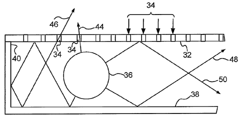
[0015] Figure 4 depicts (not to scale) an enlarged fragmented
portion of the Figure 3 light box.
CA 02608200 2007-11-13
WO 2006/128274 PCT/CA2006/000030
-6-
[0016] Figure 5A graphically depicts a Monte Carlo ray tracing
simulation of luminance distribution over the light emitting surface of a
single light bulb prior art light box schematically depicted below the
graph. Figure 5B graphically depicts a Monte Carlo ray tracing simula-
tion of luminance distribution over the light emitting surface of an
improved single light bulb light box as schematically depicted below the
graph. In both graphs luminance is plotted as a function of horizontal
position on the surface of the light box.
[0017] Figure 6 is a schematic top cross-sectional view (not to
scale) of a light box in a high dynamic range image display context.
Description
[0018] Throughout the following description, specific details are
set forth in order to provide a more thorough understanding of what is
disclosed. However, what is disclosed may be practiced without these
particulars. In other instances, well known elements have not been
shown or described in detail to avoid unnecessarily obscuring the
disclosure. Accordingly, the description and drawings are to be re-
garded in an illustrative, rather than a restrictive, sense.
[0019] VikutiTM Enhanced Specular Reflector (ESR) inulti-layer
optical film (available from 3M Electronic Display Lighting, Optical
Systems Division, St. Paul, MN) is preferably used as the reflector
material in a variable transmissivity reflector. Such film has an intrin-
sic reflectance value of about 99 %, meaning that about 99 % of all light
rays incident upon the film are reflected. Prior art variable transmissiv-
ity reflectors are typically formed using materials having intrinsic
reflectance values no greater than about 90%. Although maximal
benefit is attained by utilizing a multi-layer optical film having an
intrinsic reflectance value of about 99% or greater, persons skilled in
the art will understand that significant benefits can be attained by
utilizing a multi-layer optical film having an intrinsic reflectance value
CA 02608200 2007-11-13
WO 2006/128274 PCT/CA2006/000030
-7-
of about 98 % or greater, with lesser-albeit acceptable in some appli-
cations-benefits being attainable by utilizing a multi-layer optical film
having an intrinsic reflectance value greater than about 95 %.
Luminance Compensation
[0020] One embodiment facilitates luminance compensation of
light boxes like those depicted in Figures 1 and 2. Figure 3 depicts
such a light box 30 having a light emitting surface 32 having an intrinsic
reflectance value greater than 95 % and preferably about 99 % or
greater. This can for example be achieved by forming light emitting
surface 32 of the VikutiTM ESR multi-layer optical film mentioned
above. A large plurality of perforations 34 are provided through light
emitting surface 32, to give light emitting surface 32 a desired macro-
scopically non-varying extrinsic reflectance-reducing transmissivity
characteristic as explained below. The size of and positional distribu-
tion of perforations 34 is greatly exaggerated in Figure 1. In practice,
each perforation 34 has a diameter of about 0.5 mm and the perfora-
tions are macroscopically positioned witll uniform density per unit area
on light emitting surface 32 to impart the desired macroscopically non-
varying transmissivity characteristic to light emitting surface 32 in a
manner well known to persons skilled in the art, as aforesaid.
[0021] The interior of light box 30 contains and is illuminated by a
plurality of fluorescent tubes 36, only two of which are shown in Figure
3. Light box 30's inside rearward surface 38 and inside side surfaces
40, 42 are formed of or lined with a material (e.g. the VikutiTM ESR
multi-layer optical film mentioned above) having an intrinsic reflectance
value greater than 95 % and preferably about 99 % or greater. The
width W of light box 30 can be less than would normally be tolerable.
More particularly, the ratio W/S of the width W of light box 30 com-
pared to the centre-to-centre spacing S between adjacent fluorescent
CA 02608200 2007-11-13
WO 2006/128274 PCT/CA2006/000030
-8-
tubes 36, can be of order 0.1-a 10-fold reduction in comparison to the
Figure 1 prior art structure.
[0022] Forming light emitting surface 32 of multi-layer optical
film achieves more efficient utilization of light rays emitted by fluores-
cent tubes 36. Moreover, because multi-layer optical film can reflect
light rays many times before the rays are absorbed and lost, light
emitting surface 32 may have a non-varying transmissivity characteris-
tic. That is, the transmissivity characteristic may simply be a macro-
scopically constant, low light transmission value at all points on the
surface of light emitting surface 32, without causing an unacceptable
loss in efficiency.
[0023] For example, if the size and positional distribution of
perforations 34 are selected such that 10% of the light rays emitted by
fluorescent tubes 36 are transmitted directly through perforations 34
without reflection (as in the case of ray 44 shown in Figure 4), the high
reflectance of light emitting surface 32 ensures that substantially all of
the remaining 90 % of light rays will eventually be transmitted through
perforations 34 after an average of about 20 reflections per light ray (as
schematically illustrated by rays 46, 48 and 50 shown in Figure 4).
Because that remaining 90 % of light rays undergo many reflections
before being transmitted through a randomly encountered one of perfo-
rations 34, the net effect is that the light rays are transmitted more
uniformly tllrough all points on the surface of light emitting surface 32
than would otherwise be the case.
[0024] Light box luminance compensation utilizing prior art
reflective materials requires cumbersome, time-consuming, iterative
trial and error techniques which must be customized for each light box
in order to compensate for light absorption losses by imparting a vari-
able transmissivity characteristic to the reflective material. The need
for such compensation can be avoided-instead of utilizing a reflector
with a variable transmissivity characteristic, one may employ a reflec-
CA 02608200 2007-11-13
WO 2006/128274 PCT/CA2006/000030
-9-
tive material having a macroscopically non-varying extrinsic reflect-
ance-reducing transmissivity characteristic as aforesaid. For example, a
suitable reflector can be constructed by perforating multi-layer optical
film to give the film a macroscopically constant, low light transmission
value-a very significant advantage over the prior art.
[0025] Figures 5A and 5B respectively schematically depict Monte
Carlo ray tracing simulations of a single light bulb thin prior art light
box (Figure 5A), and an improved light box (Figure 5B). The rela-
tively uniform luminance of the Figure 5B embodiment is made appar-
ent by the relatively flat plot of luminance values. The graphical
portion of Figure 5A depicts a slight dip in the luminance values di-
rectly above the fluorescent tube. This is due to the high reflectance of
the multi-layer optical film. In most cases, especially at points on the
light emitting surface which are close to the fluorescent tube, the
luminance perceived by an observer is a composite of (1) luminance due
to light rays which are transmitted directly from the fluorescent tube
through perforations 34 without reflection; and (2) luminance due to
reflection of the tube's image in the multi-layer optical film. However,
if the light box is viewed from directly above, as illustrated in Figure
5A, the luminance contribution of light rays due to reflection of the
fluorescent tube's image is largely obscured by the tube itself. This
results in the slight dip in luminance intensity shown in Figure 5A.
[0026] It is not essential to perforate multi-layer optical film to
permit light to escape through the film in order to achieve luminance
compensation as described above. Other techniques can be used to
allow light to controllably escape through the film. One approach is to
optically couple a diffusive material to both sides of the multi-layer
optical film to controllably enable some light to escape through film, as
disclosed in Liu et al United States Patent No. 6,208,466 issued 27
March 2001. As one example, a half-tone or dot pattern of diffusive
white ink can be printed on the film to control the amount of light
CA 02608200 2007-11-13
WO 2006/128274 PCT/CA2006/000030
- 10-
transmitted through the film. Another approach is to "damage" the film
in selected regions by disrupting the film's light reflecting capability and
imparting a light transmissive capability to the film in such regions, e.g.
by thermally degrading the film in such regions, or by using a laser
beam to render the film substantially transparent in such regions,
without perforating the film.
High Dynamic Range Ima=ge Display
[0027] A second embodiment facilitates production of high dy-
namic range static images. The second embodiment also utilizes multi-
layer optical film having an intrinsic reflectance value greater than 95 %
(preferably about 99 % or greater) and having a predefined variable
transmissivity characteristic, corresponding to a predefined static image
such as an advertisement which is to be displayed by mounting a trans-
parent slleet 60 (Figure 6) bearing the image on light box 62 and operat-
ing light box 62 to back light the image.
[0028] Light box 62 has a light emitting surface 64 having a first
portion corresponding to a substantial area of light emitting surface 64,
and a second portion corresponding to the remaining area of light
emitting surface 64, excluding the first portion. Neither the first
portion nor the second portion need be a contiguous segment of light
emitting surface 64; each portion may be a plurality of non-contiguous
segments of light emitting surface 64. The first portion of light emitting
surface 64 is formed of multi-layer optical film having an intrinsic
reflectance value greater than 95 % and preferably about 99 % or
greater. The first portion of light emitting surface 64 also has a first
extrinsic reflectance-reducing characteristic (e.g. perforations) giving
the first portion a first light transmissivity characteristic of less than
%, the first transmissivity characteristic being macroscopically invari-
ant as a function of position over the first portion.
CA 02608200 2007-11-13
WO 2006/128274 PCT/CA2006/000030
-11-
[0029] The second portion of light emitting surface 64 has a
second extrinsic reflectance-reducing characteristic giving the second
portion a second light transmissivity characteristic of greater than 25 %.
For example, a large plurality of perforations 66 can be provided
through the second portion of light emitting surface 64, to give the
second portion the desired second light transmissivity characteristic of
greater than 25 %. The size and positional distribution of perforations
66 is greatly exaggerated in Figure 6. In practice, each perforation 66
may have a diameter of about 0.5 nun. However, the diameter of
perforations 66 and their density per unit area on the second portion of
light emitting surface 64 can be selectably varied, in a manner well
known to persons skilled in the art, to allow more or less light to escape
through selected regions of the second portion of light emitting surface
64 so that brighter regions of image 60 will be illuminated more than
darker regions of image 60, thus imparting the desired overall trans-
missivity characteristic to light emitting surface 64.
[0030] The interior of light box 62 contains and is illuminated by a
plurality of fluorescent tubes 68, only two of which are shown in Figure
6. That is, the inward side of light emitting surface 64 is backlit.
Light box 62's inside rearward surface 70 and inside side surfaces 72,
74 are lined with multi-layer optical film having an intrinsic reflectance
value greater than 95 % and preferably about 99 % or greater.
[0031] The variable transmissivity characteristic of light emitting
surface 64 corresponds to sheet 60, which bears a static image. Sheet
60 extends substantially parallel to and in close proximity to the out-
ward side of light emitting surface 64. The image consists of one or
more normal luminance display regions and one or more high lumi-
nance display regions. Each normal luminance display region has the
same size and shape as a corresponding segment of the first portion of
light emitting surface 64. The normal luminance display regions have a
third transmissivity characteristic which varies as a selected function of
CA 02608200 2009-09-01
-12-
a desired normal luminance characteristic of the image. Each high
luminance display region has the same size and shape as a correspond-
ing segment of the second portion of light emitting surface 64. The high
luminance display regions have a fourth transmissivity characteristic
which varies as a selected function of a desired high luminance charac-
teristic of the image. The third and fourth transmissivity characteristics
of image-bearing sheet 60 are selected such that, in combination with
the first and second transmissivity characteristics of light emitting
surface 64, the resultant mathematical product of reflectances yields a
net reflectance as a function of position corresponding to a selected high
dynamic range image. Accordingly, the first, second, third and fourth
light transmissivity characteristics together impart the desired high
dynamic range to the image when the inward side of light emitting
surface 64 is backlit.
[0032] Those portions of sheet 60 bearing high luminance display
regions of the image (e.g. brighter parts of the image which are to be
displayed at increased luminance) are more highly perforated than
portions of sheet 60 bearing normal luminance display regions of the
image which are to be displayed at reduced luminance (e.g. darker parts
of the image). Alternatively, one may selectably remove those portions
of the film which bear the high luminance display regions of the image
in order to maximize the luminance of certain image highlights corre-
sponding to those regions. The previously mentioned techniques can
also be used to allow light to controllably escape through the film,
without perforating the film. That is, one may optically couple a
diffusive material to both sides of the multi-layer optical film to control-
lably enable some light to escape through film, as disclosed in Liu et al
United States Patent No. 6,208,466 issued 27 March 2001; or, "dam-
age" the film in selected regions by disrupting the film's light reflecting
capability and imparting a light transmissive capability to the film in
such regions.
CA 02608200 2007-11-13
WO 2006/128274 PCT/CA2006/000030
-13-
[0033] The highly reflective multi-layer optical film "recycles"
light rays which would otherwise be lost due to absorption by a prior art
reflective material having a lower intrinsic reflectance value than the
preferred multi-layer optical film. Specifically, the high reflectance of
light emitting surface 64 ensures that most light rays emitted by fluores-
cent tubes 68 which are not transmitted through perforations 66 (or
which do not escape through the film in accordance with some other
technique) are reflected within light box 62 and eventually transmitted
through perforations 66 after an average of about 20 reflections per
light ray. This is especially advantageous in the display of high dy-
namic range images, since in most such images only a very small
amount of the image is at full brightness. High light reflectance within
light box 62 makes it possible to achieve much higher brightness illumi-
nation of the image (due to low loss multiple reflections of light rays)
than would otherwise be the case.
[0034] In summary, high dynamic range images can be produced
in either of two distinctly different ways. The first method uses a
variably transmissive multi-layer optical film, in which regions corre-
sponding to the bright regions of the image are more transmissive and
regions corresponding to the dark regions of the image are less
transmissive. The desired variable transmissivity characteristic can be
achieved by either varying the size of the light transmissive perfora-
tions, or varying the size of the light transmissive pattern components
(e.g. diffusive white ink dots), as long as the individual perforations or
pattern components are invisible at reasonable viewing distances; and/or
by varying the density of the light transmissive perforations or pattern
components. When such a variably transmissive multi-layer optical film
layer is combined with the image, the result is a high dynamic range
image. The second method combines a uniformly transmissive multi-
layer optical film with the image. To achieve high dynamic range, the
CA 02608200 2007-11-13
WO 2006/128274 PCT/CA2006/000030
-14-
film can be entirely removed in selected regions in order to maximize
the luminance of image highlights corresponding to those regions.
[0035] The above-described luminance compensation technique
can also be applied to the display of high dynamic range static images to
reduce the width W of light box 62, making it possible for light box 62
to be thinner than would other wise be the case, improving the practi-
cality of light box 62 in image display applications.
[0036] Variably transmissive multi-layer optical film suitable for
use with either the luminance compensation or high dynamic range
image display embodiments described above can be fabricated in vari-
ous ways. As one example, the film itself can be modified to degrade
its light reflecting capability and enhance its light transmitting capabil-
ity. In principle this is easily done since it is difficult in practice to
fabricate multi-layer optical film with suitably high reflectance. It is
less challenging, in practice, to fabricate a film having a lower
reflectance characteristic and a selected transmittance characteristic,
although it can be difficult to achieve uniform transmittance as a func-
tion of wavelength, especially for all viewing angles. As another
example, highly reflective multi-layer optical film can be perforated as
aforesaid. In principle the perforations can be so small that they are
imperceptible to an observer when the film is viewed from a reasonable
distance (e.g. distances typical for observing signs) or viewed through a
diffuser applied over the film or over the image. Spatial techniques can
also be used to vary the film's light transmitting capability, e.g. by
applying a positionally varying half tone pattern to the film, with the
pattern varying in proportion to the desired level of light transmission at
each position on the image. Another approach is to employ a film
having a non-zero, but low light transmittance characteristic (say 55'o),
and perforate only those portions of the film corresponding to high
brightness regions of the image. Automated cutting devices are readily
available in the sign industry and are easily adapted to such perforation.
CA 02608200 2007-11-13
WO 2006/128274 PCT/CA2006/000030
-15-
[0037] As will be apparent to those skilled in the art in the light of
the foregoing disclosure, many alterations and modifications are possi-
ble without departing from the spirit or scope of this disclosure.
Accordingly, the scope of the disclosure is to be construed in accor-
dance with the substance defined by the following claims.