Note: Descriptions are shown in the official language in which they were submitted.
CA 02608353 2013-02-28
METHOD AND APPARATUS FOR RAPID INTERPRETIVE ANALYSIS OF
ELECTROCARDIOGRAPHIC WAVEFORMS
BACKGROUND OF ILLUSTRATIVE EMBODIMENTS OF THE INVENTION
[00021 The heart is a pump comprised of muscle tissue that responds to
electrical
stimulation. A heartbeat is a precisely controlled event that relies on
synchronization
between the atrial and ventricular chambers to maximize pumping efficiency.
The
sinoatrial node, which is located in the right atrium of the heart, generates
the
electrical stimulus. In a healthy person, the sinoatrial node normally
generates
electrical stimulus signals at a 60-100 Hz rate, and the waves of myocardial
excitation
and contraction spread throughout the heart in well-defined manner. The
electrical
stimulus signals cause contractions in the heart's chambers, thereby pumping
blood
through the chambers. The left and right atria of the heart contract first and
for a brief
time, and then the left and right ventricles contract for a brief time. Normal
heart
rhythm is referred to as "sinus" rhythm, because it originates in the
sinoatrial node
(also referred to as the sinus node). The electrical stimulus signal output by
the
sinoatrial node is first sent to the left and right atria, then through the
atrioventricular
node and into the left and right ventricles.
[0003] An electrocardiogram ("ECG") measures the heart's electrical activity.
Electrodes are placed at specific locations on the body to capture a tracing
of the
heart's electrical activity. The electrical activity resulting from heart
depolarization
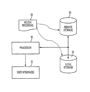
and heart repolarization is recorded by each lead. The ECG is a summation of
the
information recorded from each lead. The captured ECG reflects the direction
of
CA 02608353 2007-11-13
WO 2006/124788
PCT/US2006/018756
electrical current flow, and the magnitude of the muscle that is depolarized.
Therefore, when the atria depolarize (and contract) the ECG tracing is smaller
as
compared to when the ventricles contract, since the atria are much smaller
than the
ventricles. Ventricle repolarization is in the same direction (positive) as
ventricle
depolarization. Although an ECG is positive during membrane depolarization and
negative during repolarization, the direction with respect to ventricles is
the same
since ventricles depolarize from the inside to the outside (endocardium to
epicardium), while repolarization occurs in the opposite direction.
[0004] Referring to FIG. 1, an ECG tracing is illustrated. The cardiac cycle
begins
with a P-wave, wherein the spontaneously firing cells in the sinoatrial node
reach a
threshold and generate action potentials. A wave of depolarization spreads to
the left
and downward though left and right atria, which is labeled in FIG. 1 as the "P
wave."
The atria that were hyperpolarized suddenly become depolarized, and the ECG
records a positive deflection. When the left and right atria become
depolarized, the
ECG returns to zero. The electrical current passes through the
atrioventricular node,
causing a delay of about one-tenth of a second. Due to the small mass of the
atrioventricular node, the ECG tracing does not record any electrical
activity. When
the atrioventricular node is depolarized, it triggers depolarization of the
Purkinje
fibers. The Purkinje fibers spread the electrical current throughout the left
and right
ventricles, thereby causing depolarization across each ventricle
simultaneously. Since
the tissue mass of the Purkinje fibers is small, the ECG tracing does not
record any
electrical activity. The passing of the electrical current through the
atrioventricular
node and the Purkinje fibers is labeled in FIG. 1 as the "PR segment."
[0005] The depolarization of the left and right ventricles is referred to as
the "QRS
complex," and FIG. 1 is labeled as such. The QRS complex is quite large since
the
2
CA 02608353 2007-11-13
WO 2006/124788
PCT/US2006/018756
left and right ventricle tissue is large in comparison to the sinoatrial node.
The three
peaks are indicative of the manner in which the electrical current spreads
through the
left and right ventricles (i.e., from inside to outside) and indicative of the
fact that the
tissue mass of the left ventricle is greater than the tissue mass of the right
ventricle.
The complete depolarization of the left and right ventricles indicates that
the QRS
complex has terminated.
[0006] Referring to FIG. 2, the points of the QRS complex are labeled. As
noted
above, the QRS complex is indicative of the depolarization of the left and
right
ventricles. The ventricular depolarization begins at a left side of the
intraventricular
septum, and the peak of this depolarization is shown by the "Q" peak of the
QRS
complex. The ventricular depolarization spreads from the endocardial surface
of the
left ventricle to the epicardial surface of the left ventricle, and is shown
by the "R"
peak of the QRS complex. The spread of the ventricular depolarization to the
right
ventricle is shown by the "S" peak of the QRS complex.
[0007] The segment labeled "T wave" in FIG. 1 indicates repolarization of the
left
and right ventricles. Although the left and right ventricles are repolarizing,
the T
wave is positive, since the heart repolarizes from outside to inside, which is
the
opposite direction of depolarization (inside to outside). The completion of
the T wave
signals marks the end of the cardiac cycle.
[0008] Referring to FIG. 3, the captured tracing of electrical activity is
printed out
on a paper tape or is presented on a display. Anomalies in an ECG waveform are
indicative of various heart-related conditions, such as ischemia, myocardial
infarction,
conduction disorder, electrolyte disturbance, pericarditis, valve disease or
enlarged
heart. Certain arrhythmias might occur only on an intermittent basis, or only
if certain
psychological or physical factors (i.e., stress, fatigue, etc.) are present.
Since a typical
3
CA 02608353 2007-11-13
WO 2006/124788
PCT/US2006/018756
ECG tracing is only a few minutes in length, arrhythmias of this type are
difficult to
capture. A more lengthy ECG tracing, referred to as a Holter monitor, is used
to
capture any arrhythmias or other abnormal activity. The Holter monitor may
record a
heart's activity over a period of several days.
[0009] Referring to FIG. 1, one of the segments that is measured is the
referred to as
the QT interval, and the QT interval indicates the duration of the electrical
activity
that controls' contraction of the cells of the heart muscle. The QT interval
represents
the duration of ventricular depolarization and subsequent repolarization,
beginning at
the initiation of the Q wave of the QRS complex and ending where the T wave
returns
to the isoelectric baseline. QT interval prolongation creates an
electrophysiological
environment that favors the development of cardiac arrhythmias, most commonly
torsade de pointes, but possibly other ventricular arrhythmias as well. Long
QT
syndrome identifies a condition wherein there exists an abnormally long QT
interval
on the ECG tracing. The term "congenital long QT" refers to a long QT interval
that
is inherited. The inherited form occurs due to irregularities in particular
heart cell
proteins, and, of course, these protein irregularities are caused by
abnormalities in the
genes that produce those proteins. The term "acquired long QT" refers to a
long QT
interval that is brought about by drugs or anomalous levels of the salts
within blood
(e.g., potassium and magnesium).
[0010] Although a person might have an unremarkable QT interval under normal
conditions, that person might develop a prolonged QT or suffer torsades de
pointes
("TdP") when taking certain medications. As shown in FIG. 4, TdP refers to the
characteristic appearance of the electrocardiogram indicative of a rhythm
abnormality,
and typically occurs in the setting of a prolonged QT interval on the
electrocardiogram. TdP is a polymorphic ventricular tachyarrhythmia that
manifests
4
CA 02608353 2007-11-13
WO 2006/124788
PCT/US2006/018756
on the ECG tracing as continuous twisting of the vector of the QRS complex
around
the isoelectric baseline. A feature of TdP is pronounced prolongation of the
QT
interval in the sinus beats preceding the arrhythmia. TdP can degenerate into
life-
threatening cardiac rhythms that can result in blackouts or sudden death.
Measurement of the QT interval on the ECG tracing is still the main method of
determining whether a person has long QT interval syndrome, whether inherited
or
acquired.
[0011] Non-antiarrhythmic drugs can have an undesirable side effect of causing
delayed cardiac repolarization. Due to its relationship to heart rate, the QT
interval is
normalized into a heart rate independent "corrected" value known as the QT e
interval,
which represents the QT interval at a standardized heart rate (essentially the
QT
interval at a heart rate of 60 bpm). Several drugs that have caused TdP
clearly
increase both the absolute QT interval and the QT c interval.
SUMMARY OF ILLUSTRATIVE EMBODIMENTS OF THE INVENTION
[0012] Illustrative, non-limiting embodiments of the present invention
overcome
various disadvantages. In addition, the present invention is not required to
overcome
these disadvantages, and an illustrative, non-limiting embodiment of the
present
invention may not overcome any disadvantages.
According to one embodiment, a method for analyzing a subject-visit group of
ECG waveforms is provided. In one implementation, the method selects a subject-
visit group from a plurality of subject-visit groups, scans each ECG waveform
of the
subject-visit group for artifact, and annotates ECG waveforms containing
artifact.
Also, the method determines if measurement calipers are present in each ECG
waveform and adds measurement calipers to ECG waveforms lacking measurement
CA 02608353 2015-08-14
calipers. The method also comprises assigning a preliminary interpretation to
each ECG
waveform that lacks a preliminary interpretation. Furthermore, the method
assigns a grouping
metric to each ECG waveform and segregates ECG waveforms according to their
grouping
metric for display and evaluation.
According to another embodiment, an apparatus and software routine that
perform the
method are provided.
A method for analyzing a subject-visit group of ECG waveforms using a computer
is
provided. The method comprises selecting, by the computer, a subject-visit
group from a
plurality of subject-visit groups; scanning, by the computer, each of the ECG
waveforms of the
subject-visit group for artifact and annotating the ECG waveforms containing
artifact;
determining, by the computer, if measurement calipers are present in each of
the ECG
waveforms and adding measurement calipers to the ECG waveforms lacking
measurement
calipers; assigning, by the computer, a grouping metric to each of the ECG
waveforms; and
segregating the ECG waveforms according to the grouping metric assigned to
each of the ECG
waveforms for display and evaluation.
A method for segregating a subject-visit group of ECG waveforms using a
computer, the
method comprising: selecting, by the computer, a subject-visit group from a
plurality of subject-
visit groups; scanning, by the computer, each of the ECG waveforms of the
subject-visit group
for artifact and annotating the ECG waveforms containing artifact;
determining, by the computer,
if measurement calipers are present in each of the ECG waveforms not
containing artifact and
adding measurement calipers to the ECG waveforms lacking measurement calipers;
assigning,
by the computer, a grouping metric to each of the ECG waveforms having
measurement calipers
and not containing artifact; segregating the ECG waveforms according to the
grouping metric
assigned to each of the ECG waveforms for display and evaluation; and
displaying a plurality of
the segregated ECG waveforms concurrently on a single screen, wherein the
plurality of the
segregated waveforms are displayed grouped according to the grouping metric.
[0013]
Additional aspects of the illustrative, non-limiting embodiments of the
invention will
be set forth, in part, in the description that follows. Also, one of ordinary
skill in the art may
learn other aspects by performing routine experimentation after reviewing the
application.
6
CA 02608353 2015-08-14
BRIEF DESCRIPTION OF THE DRAWINGS
[0014] Features and advantages of illustrative, non-limiting embodiments of
the invention
will become more apparent by describing some of the embodiments in detail. The
drawings,
which are incorporated in and constitute a part of this specification,
illustrate some of the
exemplary embodiments. In the drawings:
[0015] FIG. 1 is an illustration of an ECG tracing that identifies the
various segments of an
electrical profile of a normal heartbeat;
[0016] FIG. 2 is an illustration of an ECG tracing that also identifies the
various segments of
an electrical profile of a normal heartbeat;
[0017] FIG. 3 is an illustration of the output from a 12-lead ECG or Holter
monitoring
device;
[0018] FIG. 4 is an illustration of an ECG tracing showing Torsades de
Pointes (TdP);
[0019] FIG. 5 is an illustration of a non-limiting example of a computer
system for
6a
CA 02608353 2007-11-13
WO 2006/124788
PCT/US2006/018756
extracting segments from a Holter recording for analysis;
[0020] FIG. 6 is a flowchart illustrating a non-limiting example of a method
of
rapidly interpreting electrocardiograph tracings;
[0021] FIG. 7A is a flowchart illustrating a first portion of a non-limiting
example
of a method of grouping of electrocardiograph tracings based on metrics for
cardiologist interpretation;
[0022] FIG. 7B is a flowchart illustrating a second portion of a non-limiting
example of grouping of electrocardiograph tracings based on metrics for
cardiologist
interpretation;
[0023] FIG. 8 is a non-limiting example of three waveforms that are aligned
based
on their respective R peaks; and
[0024] FIG. 9 is a non-limiting example of a waveform showing the area under
the
curve (AUC) that a computer may analyze to align waveforms.
DETAILED DESCRIPTION OF THE ILLUSTRATIVE, NON-LIMITING
EMBODIMENTS OF THE INVENTION
[0025] Illustrative, non-limiting embodiments of the present invention will
now be
described more fully with reference to the accompanying drawings. A general
example of a computer (not shown) that can be used in accordance with one
embodiment will be described below.
[0026] The computer comprises one or more processors or processing units, a
system memory, and a bus that couples the various system components. The bus
can
be one or more of any of several types of bus structures, comprising a memory
bus or
memory controller, a peripheral bus, an accelerated graphics port and a
processor, or
local bus using any of a variety of bus architectures. The system memory
comprises
read only memory ("ROM") and random access memory ("RAM"). A basic
7
CA 02608353 2007-11-13
WO 2006/124788
PCT/US2006/018756
input/output system ("BIOS") may contain routines that help transfer
information
between elements within the computer, such as during boot up. The BIOS may be
stored in the ROM or in a separate memory.
[0027] The computer further comprises a hard drive for reading from and
writing to
one or more hard disks (not shown). Some computers comprise a magnetic disk
drive
for reading from and writing to a removable magnetic disk and/or comprise an
optical
disk drive for reading from or writing to a removable optical disk, such as a
CD ROM
or other optical media. The hard drive, the magnetic disk drive, and the
optical disk
drive are connected to the bus by an appropriate interface. The drives and
their
associated computer-readable media provide nonvolatile storage of computer-
readable
instructions, data structures, program modules, and other data for the
computer.
Although the exemplary environment described herein employs a hard disk, a
removable magnetic disk, and a removable optical disk, it should be
appreciated by
those skilled in the art that other types of computer-readable media, such as
magnetic
cassettes, flash memory cards, digital video disks, RAMs, ROM, carrier waves,
transmissions, etc., may also be used.
[0028] A number of program modules may be stored on the hard disk, magnetic
disk, optical disk, ROM or RAM, and these modules typically comprise an
operating
system, at least one or more application programs, other program modules, and
program data. In some computers, a user might enter commands and information
into
the computer through input devices such as a keyboard and a pointing device.
Other
input devices (not shown) may comprise a microphone, a joystick, a game pad, a
satellite dish and/or a scanner. In some instances, however, a computer might
not
have these types of input devices. These and other input devices are connected
to the
processing unit through an interface coupled to the bus. In some computers, a
8
CA 02608353 2007-11-13
WO 2006/124788
PCT/US2006/018756
monitor or other type of display device may also be connected to the bus via
an
interface, such as a video adapter. Some computers, however, do not have these
types
of display devices. In addition to monitors, the computers may have other
peripheral
output devices (not shown) such as speakers and printers.
[0029] A computer can, but need not, operate in a networked environment using
logical connections to one or more remote computers. A remote computer may be
another personal computer, a server, a router, a network PC, a peer device, or
other
common network node, and typically comprises many or all of the elements
described
above relative to the computer. The logical connections to the computer may
comprise a local area network ("LAN") and a wide area network ("WAN"). Such
networking environments are commonplace in offices, enterprise-wide computer
networks, intranets, and the Internet.
[0030] When used in a LAN networking environment, the computer is connected to
the local network through a network interface or adapter. When used in a WAN
networking environment, the computer typically comprises a modem or other
means
for establishing communications over the wide area network, such as the
Internet.
The modem, which may be internal or external, is connected to the bus via a
serial
port interface. In a networked environment, program modules for the computer,
or
portions thereof, may be stored in a memory storage device of a remote
computer. It
will be appreciated that the network connections shown are exemplary and that
other
means of establishing a communications link between the computers may be used.
[0031] Generally, the data processors of the computer are programmed with
instructions stored at different times in the various computer-readable
storage media
of the computer. Programs and operating systems are typically distributed, for
example, on floppy disks or CD-ROMs. From there, they are installed or loaded
into
9
CA 02608353 2007-11-13
WO 2006/124788
PCT/US2006/018756
the secondary memory of the computer. At execution, they are loaded at least
partially into the computer's primary electronic memory. Illustrative, non-
limiting
embodiments of the invention may comprise these and other various types of
computer-readable storage media, which contain instructions or programs for
implementing the operations described below in conjunction with a
microprocessor or
other data processor. Some embodiments may also comprise the computer itself
when it is programmed according to the methods and techniques described below.
[0032] One exemplary embodiment of the present invention comprises a method
and apparatus for assisting cardiologists in evaluating ECG waveforms. The
embodiment may contain a computer that simulates a relatively inexperienced
cardiologist who is assisting an expert cardiologist in interpreting captured
ECG
tracings. These ECG tracings or waveforms may be captured digitally via an
electrocardiograph machine or via a Holier monitor device, or they may be
digitized
from paper electrocardiograms.
[0033] In one implementation, the computer identifies artifacts in the ECG
tracings
and tentatively interprets the ECG tracings. Also, the computer may compare
several
ECG waveforms based on information known about the waveforms and may group
the waveforms accordingly.
[0034] For instance, if a cardiologist has marked one waveform as a normal
waveform and has marked another waveform as an abnormal waveform, the computer
may determine that both waveforms cannot be members of the same group, even if
they have some characteristics in common. In addition, if a cardiologist
changes the
computer's interpretation of the waveform, the computer may analyze the
changes
and regroup the remaining waveforms based on the changes.
[0035] Also, ECG tracings are stored in a variety of different file formats,
such as
CA 02608353 2007-11-13
WO 2006/124788
PCT/US2006/018756
FDA XML, Mortara XML (as exported from E-Scribe), and GE MUSE . As such,
the computer may include conversion libraries that facilitate the conversion
of the
ECG tracings, which are stored in one of these formats, into a format that the
computer uses. Thus, the conversion libraries allow the computer to process
ECG
tracings having a uniform format, without having to worry about the specific
format,
sample rate, length of recording or other details of the data for the original
ECG
tracings. Accordingly, the embodiment operates independently of the data file
size,
format, sample rate, bit depth and scale factor.
[0036] Also, a Holter recording file typically will contain 24 or 48 hours of
12-lead
data at lk samples per second. In one embodiment of the present invention, the
computer can process a Holter recording of at least 48 hours x 12 leads x 1k
samples
per second. However, the present invention clearly is not limited to such an
embodiment, and the computer may be able to handle longer recordings or
recordings
taken at higher and/or lower sampling rates.
[0037] FIG. 5 shows an example of a computer that may be used in an
illustrative,
non-limiting embodiment of the present invention. The computer comprises a
processor 50, user interfaces 51, and local storage 54. As described above,
the
processor 50 may comprise one or more processors, and the user interfaces 51
may
comprise monitors, keyboards, mice, touch-screens, etc. The processor 50 is
connected to the local storage 54 via a bus (or busses), and the local storage
54 may
comprise various types of disk memories, electronic memories (i.e., RAM, ROM,
etc.), or various combinations thereof. The processor 50 may also access a
remote
storage 53, which may comprise various types of data storage machines and/or
server
machines.
[0038] The remote storage 53 or the local storage 54 stores a Holter recording
file
11
CA 02608353 2013-02-28
52. Also, while the storage 53 or 54 stores the Holter recording file 52 in
the present
example, the remote storage 53 or local storage 54 may additionally or
alternatively
store digital ECG waveforms captured via other means. For example, the storage
53
or 54 may store a waveform captured via an electrocardiograph machine or
digitized
from paper electrocardiograms. In any event, the processor 50 accesses the
Hoher
recording file 52 from the storage 53 or 54.
[00391 Although there is no set time limit on the length of an ECG tracing
within
the Holler recording file 52, the typical length of an ECG tracing is about
ten seconds.
In the present embodiment, the time limit for the tracing is configurable, and
a default
time limit is ten seconds. Also, in one implementation, the computer truncates
ECG
tracings that are longer than the configured time limit.
[0040] The computer may also process three aspects of data. The first aspect
is a
Subject-Visit Group ("SVG"). The SVG is a set of all ECG tracings taken for a
given
test subject, and these tracings may be taken during a single visit to the
research
facility or during a single day's recording. The second aspect is a single ECG
tracing,
which is typically ten seconds in length, though other time lengths are
possible. The
ECG tracing may be extracted from a long or continuous recording or it may be
captured separately. Additional information regarding the extraction of ECG
tracings
from a continuous recording is disclosed in the co-pending utility application
which is
entitled "Method and Apparatus for Sequenced Extraction from
Electrocardiographic
Waveforms," which was invented by S. Satin, R. Cochran, and N. Patel, which
was
filed on May 15, 2006, and issued as U.S. Patent No. 8,055,331.
The third aspect is an ECG
waveform, which is a short portion of an ECG tracing and represents a single
12
CA 02608353 2007-11-13
WO 2006/124788
PCT/US2006/018756
heartbeat. The length of the ECG waveform will vary with the heart rate.
[0041] In the embodiment, the computer processes and displays one or more ECG
tracings within a particular SVG, one SVG at a time, and the cardiologist can
evaluate
and interpret the display tracing or tracings. After the cardiologist finishes
evaluating
all of the tracings within an SVG, the computer selects the next SVG for the
cardiologist examine. In one implementation, the computer selects the next SVG
based on which SVG has been stored for the longest period of time without
being
interpreted. Alternatively, the computer could select the next SVG based on
the
results of a preliminary interpretation or based on the results of a
preliminary (but
non-interpretive) screening. The preliminary interpretation or screening may
be done
by a human technician or by an automatic computerized process. Of course, the
cardiologist is free to select a particular SVG, as opposed to being limited
to viewing
and interpreting the tracings in SVGs, which have been prioritized in any
particular
order.
[0042] After the cardiologist or computer selects an SVG for interpretation,
the
cardiologist or computer can examine each ECG waveform to determine if the
wavefoinis contain "artifact." Artifact corresponds to ECG waveform data that
is
corrupted or has been affected by excessive noise. If an ECG waveform contains
artifact, it is marked accordingly.
[0043] Also, the computer may evaluate each ECG waveform in the SVG to
determine the location of a set of caliper positions. A caliper position marks
a point
on the ECG waveform, and the distance between a set of two caliper positions
on the
wavefoim corresponds to the distance between the corresponding two points on
the
waveform. In one example, the caliper positions are included as part of the
digital
data relating to the ECG waveform and can be generated by an ECG recorder, a
13
CA 02608353 2013-02-28
human technician, a separate a computer process, etc. Also, Fig. 1 shows an
illustrative example of two caliper positions CP1 and CP2 that are used to
measure the
length of the QT interval. As is evident from the figure, the distance between
the
positions CP1 and CP2 corresponds to the length of the interval.
[0044] Also, if the data corresponding to a ECG waveform lacks caliper
positions,
the computer can analyze the ECG wavefolin and assign caliper positions for
measuring the appropriate portion or portions of the waveform. An example of
an
algorithm that can analyze a waveform and measure aspects of the waveform is
disclosed in U.S. Patent No. 6,580,817, which is entitled "Apparatus and
Method for
Reading and Analyzing ECG Images," which was invented by F. Badilini, and
which
was filed on May 17, 2001.
[0045] Alternatively, the cardiologist can review the ECG waveforms and assign
measurement caliper positions thereto via an appropriate software application.
For
example, when the ECG waveform is displayed, the cardiologist can maneuver a
mouse or other input device to assign caliper positions to various positions
of the
waveform.
[0046] The computer may also perform a preliminary interpretation of each ECG
waveform, where none exists, to initially and preliminarily associate the
waveform
with a particular type of waveform. Then, the computer may include or embed
data
corresponding to the preliminary interpretation in the digital data for the
ECG
waveform data. Alternatively, a human technician may conduct a preliminary
interpretation manually and input the results to the computer. In one
implementation,
the preliminary interpretation operation evaluates certain characteristics of
the ECG
waveform and associates it with a particular type of waveform. For example,
during a
14
CA 02608353 2007-11-13
WO 2006/124788
PCT/US2006/018756
preliminary interpretation, the computer may evaluate various characteristics
of the
ECG waveform to preliminarily determine if the waveform is corresponds to a
normal
waveform or an abnormal waveform. Further interpretation may deem that one
abnormal waveform represents atrial fibrillation, and another abnormal
waveform
represents left ventricular hypertrophy.
[0047] If the computer performs a preliminary interpretation operation on an
ECG
waveforms, it may receive feedback from the cardiologist and adjust the manner
in
which it interprets waveforms based on the feedback. For example, after the
computer performs its preliminary interpretation on an ECG waveform, the
cardiologist may adjust or correct the interpretation and input these
corrections to the
computer. Then, the computer may adjust various thresholds, evaluation
parameters,
etc. of the preliminary interpretation process based on the input corrections.
[0048] Typically, conventional interpretation algorithms rely on training from
expert
cardiologists. In one particular embodiment of the present invention, the
cardiologist
essentially corrects or confirms the work of the automated preliminary
interpretation
process that the computer performs, either by changing the computer's
interpretation
or by accepting a correct interpretation. In either case, the feedback is used
to
improve the performance of the preliminary interpretation algorithm, on either
a batch
basis or a real-time (interactive) basis. As a result of this feedback
process, the
computer's preliminary interpretation of ECG waveforms is improved and the
cardiologist's workload is reduced.
[0049] After each ECG waveform is examined, a grouping metric is assigned to
the
waveform. The grouping metric is a set of one or more numeric or non-numeric
(i.e.,
text) values that reflect certain key aspects of each ECG waveform.
Accordingly, the
computer can evaluate the grouping metrics of two ECG waveforms to determine
how
CA 02608353 2007-11-13
WO 2006/124788
PCT/US2006/018756
similar the ECG waveforms are, in the sense of cardiologic interpretation. In
other
words, if two ECG waveforms have very similar grouping metrics, then the ECG
waveforms are very similar from the cardiologist's point of view.
[0050] As one example, a normal ECG waveform has predetermined shape and
characteristics. Also, an ECG waveform that represents a certain abnormality
likewise has a predetermined shape and characteristics. For example, an
abnormal
waveform that indicates that a patient has an atrial fibrillation has a first
predetermined shape and characteristics. Also, an abnormal waveform that
indicates
that a patient has a left ventricular hypertrophy has a second predetermined
shape and
characteristics. Likewise, abnormal waveforms respectively representing a
right
bundle branch block or sinus bradycardia have other predetermined shapes and
characteristics.
[0051] Thus, the computer may generate the grouping metrics by comparing the
data of an ECG waveform with the data of predetermined normal and abnormal
waveforms. For example, the computer can compare corresponding points of the
ECG waveform and the predetermined normal waveform and determine the degree to
which the ECG waveform varies or deviates from the predetermined normal
waveform at these points. In one implementation, computer measures the
deviation of
the corresponding points by determining how many pixels separate a point of
the
ECG waveforms from a corresponding point of the predetermined normal waveform.
This deviation, in terms of pixels, may be used as one factor for creating the
grouping
metric. Similarly, the computer may compare the ECG waveform with each of the
predetermined abnormal waveforms to determine how the ECG waveform varies from
each of the abnormal waveforms and may use these variations as additional
factors for
creating the grouping metric.
16
CA 02608353 2007-11-13
WO 2006/124788
PCT/US2006/018756
[0052] The computer may also determine whether or not any of the ECG waveforms
in the SVG have a preliminary interpretation that is so reliable that it can
be accepted
without the cardiologist's approval. The computer may evaluate one or more
aspects
of the preliminary interpretation to determine the reliability of the
interpretation. For
example, the computer may determine (1) if the waveform has any artifact, (2)
if the
percentage of artifact in the waveform is less than a predetermined threshold,
(3) if
the magnitude or degree of an artifact within the waveform exceeds a
predetermined
threshold, (4) if the slope of the T-wave (Figs. 1 and 2) is within a
predetermined
range, etc. If the ECG waveform has a very reliable preliminary
interpretation, the
computer may exclude the waveform from further analysis to reduce the
cardiologist's workload.
[0053] Next, the grouping metrics, as well as other available information, of
the
ECG waveforms in the SVG are examined, and the ECG waveforms are grouped
according to how similar they are, from a cardiologic point of view. For
example, in
one embodiment, the computer may evaluate the amount that the ECG waveform
deviates from each of the predetermined normal or abnormal waveforms. If the
ECG
waveform deviates from one of the predetermined waveforms (e.g., the
predetermined
abnormal waveform representing atrial fibrillation) by less than a
predetermined
amount (e.g., less than a predetermined number of pixels), the computer may
place
the ECG waveform in the "atrial fibrillation waveform" group.
[0054] During the grouping analysis, the presence of any artifact, as detected
previously or as indicated by the cardiologist, is taken into account. In
addition, the
presence of any existing preliminary interpretation, cardiologist-provided
interpretation, or automatically-accepted interpretation is taken into account
as well.
If verified measurement caliper positions are available at this point,
computer may
17
CA 02608353 2007-11-13
WO 2006/124788
PCT/US2006/018756
evaluate these measurements in the grouping analysis, along with the other
grouping
metrics.
[0055] In one example, the computer does not combine an ECG waveform with
artifacts and an artifact-free ECG waveform into the same group. Furthermore,
in one
implementation, each ECG waveform having an artifact is assigned to its own
single-
member group.
[0056] Also, in one embodiment, ECG waveforms with a final, accepted
interpretation will not be included in any group at all, regardless of whether
the final,
accepted interpretation came from a cardiologist or an automatic computer
process.
On the other hand, all ECG waveforms that lack a confirmed interpretation are
placed
into one or more groups, according to their similarity, and those groups
contain only
waveforms that are substantially similar to each other.
[0057] The computer may also employ a neural network called a self-organizing
map ("SOM") that provides information about the relationships between the
groups of
ECG waveforms. Thus, in addition to grouping similar ECG waveforms together, a
SOM also provides some indication about the relationship between groups of
waveforms. Specifically, the SOM arranges the groups in a geometric and/or
spatial
way such that it places groups, which tend to be similar to each other,
adjacent or
close to each other.
[0058] Also, in an illustrative, non-limiting embodiment, the cardiologist has
the
ability to control the coarseness or fineness of the grouping of ECG
wavefoints. For
example, when ECG waveforms are grouped, it is possible to group them too
tightly
(e.g., ECG waveforms that should be in different groups are lumped together)
or too
loosely (e.g., ECG waveforms that should be combined are grouped apart).
Either
situation creates more work for the cardiologist because the cardiologist has
to study
18
CA 02608353 2007-11-13
WO 2006/124788
PCT/US2006/018756
the grouped waveforms and revise the groups. By tightening or loosening the
grouping, the cardiologist can optimize the manner in which the computer
groups the
waveforms.
[0059] As one example of tightening or loosening the grouping, the
cardiologist can
adjust the predetermined maximum amount (e.g., the maximum number of pixels)
that
an ECG waveform can deviate from a predetermined waveform (e.g., the
predetermined atrial fibrillation waveform) and still be grouped in the
predetermined
waveform group (e.g., the "atrial fibrillation waveform" group). For example,
assume
that the computer incorrectly includes certain waveforms in the "atrial
fibrillation
waveform" group. In such case, the cardiologist can instruct the computer to
be more
selective in deciding which waveform belongs in the "atrial fibrillation
waveform"
group by decreasing the predetermined maximum amount (e.g., number of pixels)
from which a waveform can deviate from the predetermined waveform and still be
placed in the group.
[0060] Also, the computer may have a single screen to display all of the ECG
waveform groups that are associated with a particular SVG. As one example, the
screen could have a number of boxes, and each box could show all the ECG
waveforms that are assigned to a single group. Also, the computer may overlay
the
ECG waveforms, and the doctor can select the Holter lead by using a mouse or
other
device to move a cursor to the lead and select it. If there are too many boxes
to fit on
the screen at one time, a scrolling display may be created, and the computer
may
prioritize the groups based on the number of waveforms that they contain.
Then, the
computer could display the boxes corresponding to the most populous groups at
the
top of the scrolling display.
[0061] By displaying the groups of ECG waveforms in the above manner, the
19
CA 02608353 2007-11-13
WO 2006/124788
PCT/US2006/018756
cardiologist can see, at a glance, how the ECG waveforms have been grouped. If
the
cardiologist believes that the ECG waveforms are grouped too tightly (into too
few
boxes), the cardiologist can input commands to the computer to regroup the ECG
waveforms into a larger number of groups as described above. Likewise, if the
ECG
waveforms have been split up unnecessarily, the cardiologist can input
commands to
regroup the ECG waveforms into a smaller number of groups.
[0062] Also, the computer may automatically display the groups in a certain
order.
For example, the computer may display the groups in order of their size,
whereby the
largest groups, which presumably contain the most common waveforms, are
presented
first. In another implementation, the computer displays the smallest groups
first, as a
way of highlighting the least common waveforms seen during the Holter
recording.
In another instance, the computer uses the pre-existing interpretive
statements, in
combination with a grading system, to order the groups. For instance, some
interpretations that are deemed noteworthy might be displayed ahead of other,
less
remarkable interpretations. As yet another example, the computer may enable
the
cardiologist to use the screen for the adjustment of the grouping
tightness/looseness
and allow the cardiologist view all the ECG waveform groups and select a group
for
display. Alternatively, the cardiologist may be able to input a command to
select
which group he or she would like the computer to display.
[0063] Once a group of an ECG waveforms is selected for display, the computer
decomposes the waveform into one or more batches. For example, the display may
not be able to display the entire group of ECG waveforms at once because there
may
be a limit (based upon the computer hardware and/or software) on how many ECG
waveforms can be simultaneously displayed. If not all the ECG waveforms can be
displayed, the group of waveforms is divided into batches such that the number
of
CA 02608353 2007-11-13
WO 2006/124788
PCT/US2006/018756
waveforms in each batch is less than or equal to the maximum number of
waveforms
that the computer can display at once. Also, the batch may contain an entire
group of
ECG waveforms, if the entire group of waveforms does not exceed the
limitations of
the computer display.
[0064] Then, one of the batches of waveforms of the current group is selected
to be
presented to the cardiologist, and this batch is called the current display
batch. As
such, the cardiologist can quickly make a visual determination as to whether
or not all
the ECG waveforms in the current display batch are substantially identical,
from an
interpretive point of view.
[0065] With the batch displayed, the cardiologist has several options
available. The
cardiologist can alter the placement of the caliper positions on any displayed
ECG
waveform. Also, the cardiologist can assign a new interpretation to all or any
subset
of the ECG waveforms currently displayed. For example, the cardiologist can
input
commands to the computer to change the interpretation from "normal waveform"
to
"atrial fibrillation waveform." Additionally, the cardiologist can accept and
confirm
the interpretation and the caliper positions of all or any subset of the ECG
waveforms
displayed. Also, the cardiologist can accept and confirm all of the ECG
waveforms in
the current group, which includes not only the ECG waveforms in the current
display
batch, but also the remainder of the ECG waveforms in the group that are not
currently displayed. Moreover, the cardiologist can input a command to
indicate that
an ECG waveform has "artifacts," if the computer did not previously identify
and flag
the artifacts.
[0066] Once the cardiologist has made all the desired changes and accepted all
the
correct values, the computer checks to see what batches, groups, and ECG
waveforms
still need to be interpreted. If there are still unviewed ECG waveforms in the
current
' 21
CA 02608353 2007-11-13
WO 2006/124788
PCT/US2006/018756
display group, the computer selects a new batch for display. If the current
display
group has been completely reviewed, the computer selects a new group for
display.
The cardiologist can also instruct the computer to repeat the grouping process
or to
generate new preliminary interpretations.
[0067] In one implementation, the computer separately displays all of the ECG
waveforms so that the cardiologist can examine and verify the placement of the
caliper positions. As noted previously, verifying the caliper positions can be
performed after determining that each ECG waveform in a SVG has an associated
set
of caliper positions for measuring certain aspects of the waveform, such as
the QT
interval. This verification operation generally would be done if the computer
performed its automated preliminary interpretation process based on the
caliper
positions.
[0068] The ECG waveforms may be displayed in a tall scrolling list, with one
ECG
waveform per line. In such a case, the cardiologist may select the ECG or
Holter lead
waveforms to be displayed, and each selected ECG or Holter lead is overlaid
into the
same graph space, and visually differentiated by color. This process allows
the
cardiologist to choose the Holter lead or combination of Holter leads to use
when
verifying the caliper positions. Also, the computer may enable the
cardiologist to
adjust the caliper positions in situ. Moreover, the computer may enable the
cardiologist to zoom in on or otherwise enlarge each ECG waveform, so that the
calipers can be adjusted with greater precision, if necessary. After the
cardiologist
has reviewed and approved of the caliper settings and positions for an entire
scrolling
list, the cardiologist can input a command to accept the entire list.
[0069] As noted earlier, the computer receives feedback from the cardiologist
and
integrates this feedback into the preliminary interpretation algorithm. With
respect to
22
CA 02608353 2007-11-13
WO 2006/124788
PCT/US2006/018756
the changes in the caliper positions, the computer may uses the cardiologist's
feedback to train or modify the operations or applications that the computer
performs
in earlier stages of the process. Specifically, the cardiologist provides the
computer
with valuable expert information regarding caliper positions, and the computer
uses
such information to improve the manner in which calipers are positioned in the
future.
In the case in which an automated system determines the caliper positions, the
computer can generate electronic records that can be used to train the
automatic
system. In the case of human technicians, the computer can generate reports
comparing the initial and corrected caliper placements, which can be used as
part of
the technician's ongoing training.
[0070] Once all the ECG waveforms for a single SVG have been processed, the
computer repeats the process for another SVG.
[0071] In one illustrative, non-limiting embodiment, with respect to the
display
mechanism for the computer, there are two basic operating principles. First,
the
display mechanism shows multiple ECG waveforms on the screen at a single time,
in
such a way that the cardiologist can readily determine whether they are
substantially
similar to each other. Second, the display mechanism allows the cardiologist
to
rapidly select and process any desired subset of the ECG waveforms. This
processing
might entail accepting the existing interpretation, replacing the existing
interpretation
with a new interpretation, or other actions. The display mechanism also
enables the
cardiologist to examine the ECG waveforms rapidly for similarities or
differences and
to select any chosen subset of the ECG waveforms. Then, the computer processes
the
whole subset with a single operation. Also, displaying multiple waveforms
allows the
cardiologist to work more quickly if the ECG waveforms are similar, and
grouping
the ECG waveforms according to the grouping metric ensures that each displayed
,
23
CA 02608353 2007-11-13
WO 2006/124788
PCT/US2006/018756
batch of ECG waveforms will generally be very similar.
[0072] To display multiple ECG waveforms in the most visually useful way, the
computer generally aligns them in time. In one example, the computer displays
each
set of ECG waveforms in such a way that the various ECG waveform features
(e.g.,
PRS complex, R peak, Q-T interval, etc.) are all closely or exactly aligned.
Exact
alignment will not always be possible, since the ECG waveforms will not always
be
identical, but as long as the ECG waveforms are aligned closely, the
cardiologist will
still be able to evaluate the waveforms quickly.
[0073] One method of aligning ECG waveforms is to align the waveforms based on
their R peaks. FIG. 8 shows an example in which three waveforms are aligned
based
on their R peaks. Automatic identification of the R peak of an ECG waveform is
a
reasonably well-known and standard technique. Once the R peak of each ECG
waveform is identified, simply aligning the R peaks of each successive ECG
waveform results in ECG waveforms that are acceptably well aligned.
[0074] Another method of aligning ECG waveforms is to align the waveforms
based
alignment based on an RMS error minima to smooth the waveforms. This method
overlaps a pair of ECG waveforms at various time offsets, and calculates the
RMS
(root mean square) of the difference between the voltages at each point of the
two
ECG waveforms. This will yield a curve with a minimum value at the time offset
that
gives a very good alignment between the ECG waveforms.
[0075] Another method of aligning ECG waveforms is to align them based on an
"area under curve" ("AUC") maxima. This method compares areas under
corresponding portions of two ECG waveforms to find an optimum time alignment.
For example, as shown in FIG. 9, the computer may evaluate the area under the
QRS
complex (FIG. 1), which is labeled as QRS1 in FIG. 9. When the ECG waveforms
24
CA 02608353 2007-11-13
WO 2006/124788
PCT/US2006/018756
are lined up well, their common AUC will be at a peak.
[0076] FIG. 6 shows a flowchart illustrating a non-limiting example of a
process
that the computer executes to rapidly interpret ECG tracings.
[0077] First, the computer selects an SVG for evaluation (S100). As discussed
earlier, the computer may select the SVG that has not been processed and that
has
been stored for the longest period of time. Alternatively, the computer may
choose
the SVG based on the results of a preliminary interpretation or based on the
results of
a preliminary (but non-interpretive) screening. The preliminary interpretation
or
screening may be done by a human technician or by an automatic computerized
process. Of course, the cardiologist can instruct the computer to select any
particular
SVG to interpret.
[0078] Then, the computer examines each ECG waveform in the SVG to determine
if any of the waveforms contain "artifact" (S200). If an ECG waveform contains
artifact, the computer marks the ECG waveform with an appropriate designation.
For
example, the computer may add an annotation to an overlay (e.g., the RR
interval
(FIG. 1)) in the ECG waveform. While the computer may automatically detect the
artifact using an appropriate software analysis program, the cardiologist can
"manually" annotate the ECG waveform, for example, as "Unmeasurable,
Uninterpretable," by inputting appropriate commands to the computer.
[0079] After the ECG waveforms are annotated, each ECG waveform in the SVG is
analyzed to determine whether or not it contains caliper positions for
measuring
various aspects of the waveform, such as the QT interval. (S300). The caliper
positions will normally be part of the imported data, and they may be
generated by an
ECG recorder, a human technician, a computer process other than the ECG
recorder,
or other means. Also, the computer may automatically analyze each ECG waveform
CA 02608353 2007-11-13
WO 2006/124788
PCT/US2006/018756
to determine if it contains caliper positions. Alternatively, the cardiologist
may
manually inspect each waveform and input a command indicating whether or not
the
waveform has caliper positions.
[0080] If any ECG waveform lacks caliper positions (S300: No), then the
computer
analyzes the ECG waveform and, if possible, assigns caliper positions to the
wavefoliu. Alternatively, the cardiologist can review the ECG waveforms and
assign
caliper positions by inputting appropriate commands to the computer.
[0081] Subsequently, the computer determines whether or not a preliminary
interpretation is available for each ECG waveform (S400). Typically, a
preliminary
interpretation might be embedded within the ECG waveform data and may be
created
by a human technician or by another computer program. If no preliminary
interpretation exists for any of the ECG waveforms (S400: No), the computer
generates preliminary interpretations for the waveforms. Also, in one
implementation, if the computer performs a preliminary interpretation for any
of the
ECG waveforms, it performs the interpretations for all of ECG waveforms in the
SVG.
[0082] Afterwards, the computer examines each ECG waveform and assigns a group
metric to each waveform (S500). As noted above, the group metric may be a set
values that reflects certain key aspects of each ECG waveform and can be used
to
determine how similar two ECG waveforms are to each other.
[0083] In addition, the computer may determine whether or not any of the ECG
waveforms in the SVG have a preliminary interpretation that is so reliable
that it can
be accepted without cardiologist approval (S600). If an ECG waveform has a
preliminary interpretation that is sufficiently reliable, the computer exempts
the
waveform from further analysis, and exempting reliably interpreted waveforms
26
CA 02608353 2007-11-13
WO 2006/124788
PCT/US2006/018756
reduces the cardiologist's workload.
[0084] Next, the computer analyzes the grouping metrics, as well as other
available
information, of the ECG waveforms in the SVG and groups similar ECG waveforms
within the SVG with each other (S700). During the grouping analysis, the
computer
considers the presence of any artifacts, as detected previously or as
indicated by the
cardiologist. Also, the computer may consider the presence of any existing
preliminary interpretation, cardiologist-provided interpretation, or
automatically-
accepted interpretation. Furthermore, if verified caliper positions are
available, the
computer may take them into account in the grouping analysis, along with the
other
grouping metrics.
[0085] FIGS. 7A and 7B show a flowchart illustrating a non-limiting example of
a
process that the computer executes to group similar ECG waveforms within the
SVG
with each other.
[0086] Initially, the computer determines if any of the ECG waveforms within
the
SVG contain artifacts (S710). If an artifact is present in an ECG waveform
(S710:
Yes), the computer assigns the waveform to its own single-member group (S715).
[00871 Similarly, the computer determines if any of the ECG waveforms in the
SVG
has a final, accepted interpretation (S720). In one embodiment, the computer
determines that the waveform has a final, accepted interpretation if the
computer
determined that it had a sufficiently reliable preliminary interpretation in
operation
S600. Alternatively or additionally, the computer may determine that a
waveform has
a final, accepted interpretation if the cardiologist has previously designated
the
waveform as being finally accepted. If an ECG waveform has a final, accepted
interpretation (S720: Yes), the computer does not include it in any group at
all,
regardless of whether the final, accepted interpretation came from the
cardiologist or
27
CA 02608353 2007-11-13
WO 2006/124788
PCT/US2006/018756
an automatic computer process (S725).
[0088] Next, the computer groups the remaining ECG waveforms, which do not
contain artifacts and which do not have final, accepted interpretations,
according to
their group metric values (S730). In other words, the computer places the
remaining
ECG waveforms into one or more groups, according to their similarity, such
that each
group only contains waveforms that are substantially similar to each other.
[0089] As noted above, the cardiologist has the ability to control the
coarseness or
fineness of the grouping of ECG waveforms. For example, when the computer
groups the ECG waveforms, it possibly may group them too tightly (e.g., ECG
waveforms that should be in different groups are lumped together) or too
loosely (e.g.,
ECG waveforms that should be combined are grouped apart). Either situation
creates
more work for the cardiologist. Therefore, the cardiologist has the ability to
instruct
the computer to tighten or loosen the manner in which it groups the waveforms.
[0090] Specifically, if the cardiologist believes that the ECG waveforms are
grouped
too tightly (S740: Yes), he or she can instruct the computer to loosen the
parameters
of the group metrics that the computer uses to group ECG waveforms (S745).
Conversely, if the cardiologist believes that the ECG waveforms are grouped
too
loosely (S750: Yes), he or she can instruct the computer to tighten the
parameters of
the group metrics that the computer uses to group ECG waveforms (S755). Also,
as
described previously, the computer may employ an SOM to indicate the
relationship
between the various groups. Specifically, similar ECG waveforms are placed in
respective groups, and the SOM identifies similarities among the groups.
[0091] After the computer has initially grouped the ECG waveforms in a
particular
SVG, the computer may display the waveform groups on a display so that the
cardiologist can evaluate the groups. The display could contain a screen
having a
28
CA 02608353 2007-11-13
WO 2006/124788
PCT/US2006/018756
number of boxes, and each box could show all the ECG waveforms that are
assigned
to a single group. Also, the computer may overlay the ECG waveforms, and the
doctor can select the Holter lead by using a mouse or other device to move a
cursor to
the lead and select it. If there are too many boxes to fit on the screen at
one time, a
scrolling display may be created, and the computer may prioritize the groups
based on
the number of waveforms that they contain. Then, the computer could display
the
boxes corresponding to the most populous groups at the top of the scrolling
display.
[0092] As noted in FIG. 7B, the computer selects which group of ECG waveforms
to display for analysis (S760). For example, as described above, the computer
may
automatically display the largest groups first or may display the smallest
groups first.
In another implementation, the computer uses the pre-existing interpretive
statements,
in combination with a grading system, to determine which group to display.
Also, the
cardiologist may be able to input a command to select which group he or she
would
like the computer to display.
[0093] Once a group of ECG waveforms is selected for display, the computer
decomposes the waveforms into one or more batches (S765). For example, the
display may not be able to display the entire group of ECG waveforms at once
because there may be a limit (based upon the computer hardware and/or
software) on
how many ECG waveforms can be simultaneously displayed. If not all the ECG
waveforms can be displayed, the group of waveforms is divided into batches
such that
the number of waveforms in each batch is less than or equal to the maximum
number
of waveforms that the computer can display at once. Also, the batch may
contain an
entire group of ECG waveforms, if the entire group of waveforms does not
exceed the
limitations of the computer display.
[0094] Then, one of the batches of waveforms of the current group is selected
to be
29
CA 02608353 2007-11-13
WO 2006/124788
PCT/US2006/018756
presented to the cardiologist (S770). Accordingly, the cardiologist evaluates
the ECG
waveforms in the displayed batch and determines whether or not they are
substantially
the same (S780).
[0095] For example, while the batch displayed, the cardiologist can alter the
placement of the caliper positions on any displayed ECG waveform. Also, the
cardiologist can assign a new interpretation to all or any subset of the ECG
waveforms currently displayed. Additionally, the cardiologist can accept and
confirm
the interpretation and the caliper positions of all or any subset of the ECG
waveforms
displayed. Also, the cardiologist input a command to indicate that an ECG
waveform
has "artifacts," if the computer did not previously identify and flag the
artifacts.
[0096] Once the cardiologist has made all the desired changes and accepted all
the
correct values, the computer checks to see what batches, groups, and ECG
waveforms
in the SVG still need to be interpreted (S785). If there are still unviewed
ECG
waveforms in the current display group, the computer selects a new batch for
display.
(S785: Yes).
[0097] If the current display group has been completely reviewed (S785: No),
the
computer displays all of the ECG waveforms in the group so that the
cardiologist can
examine, verify, and approve of the placement of the caliper positions for the
group
(S790). Also, as noted above, the ECG waveforms may be displayed in a tall
scrolling list, with one ECG waveform per line. In such a case, the
cardiologist may
select the ECG or Holter lead waveforms to be displayed, and each selected ECG
or
Holter lead is overlaid into the same graph space, and visually differentiated
by color.
This process allows the cardiologist to choose the ECG or Holter lead or
combination
of ECG or Holter leads to use when verifying the caliper positions. Also, the
computer may enable the cardiologist to adjust the caliper positions, as
discussed
CA 02608353 2013-02-28
above.
[0098] As previously noted, the computer receives feedback from the
cardiologist
and integrates this feedback into the preliminary interpretation algorithm.
With
respect to the changes in the caliper positions, the computer may use the
cardiologist's
feedback to train or modify the operations or applications that the computer
performs
in earlier stages of the process. Specifically, the cardiologist provides the
computer
with valuable expert information regarding caliper positions, and the computer
uses
such information to improve the manner in which calipers are positioned in the
future.
In the case in which an automated system determines the caliper positions, the
computer can generate electronic records that can be used to train the
automatic
system. In the case of human technicians, the computer can generate reports
comparing the initial and corrected caliper placements, which can be used as
part of
the technician's ongoing training.
[0099] Also, the manner in which the ECG waveforms are finally interpreted and
grouped are fed back to the computer, and the computer uses such information
to
assist it with its interpretation and grouping of future waveforms.
[00100] Once all the ECG waveforms for a single SVG have been processed, the
computer repeats the process for another SVG.
[00101] The foregoing description of the exemplary embodiments of the
invention
has been presented for purposes of illustration and description.
The exemplary embodiments were chosen and described in
order to explain the principles of the invention and its practical application
to enable
one skilled in the art to utilize the invention in various exemplary
embodiments and
31
CA 02608353 2013-02-28
with various modifications as are suited to the particular use contemplated.
[00102] The scope of the claims should not be limited by the preferred
embodiments
set forth in the examples, but should be given the broadest interpretation
consistent
with the description as a whole.
32