Note: Descriptions are shown in the official language in which they were submitted.
CA 02608400 2012-12-20
91627-65
1
SUPPORT FOR USE IN MICROCHANNEL PROCESSING
Technical Field
The disclosed technology relates to supports for use in microchannel
processing. These supports may be used for supporting catalysts used in
to microchannel reactors. The supports may be used for supporting sorption
medium
used in microchannel separators. The supports may be in the form of porous
supports
on interior walls of process microchannels in the microchannel reactors or
separators.
The porous supports may comprise microgrooved support strips or shims. The
supports may comprise porous, thermally conductive treatment or coating
layers.
Microchannel reactors containing catalysts supported by these supports may be
referred to as structured wall (SW) reactors.
Background
Microchannel reactors may be used in a variety of catalytic processes wherein
reactants contact a catalyst within the microchannel reactor and undergo
reaction.
These reactors have been shown to provide excellent performance and attractive
economics for steam methane reforming (SMR) reactions at very short contact
times
using a catalyst coated on the interior walls of the microchannel reactor.
However,
reactions with longer contact times have in the past required either an
engineered
catalyst (e.g., a catalyst supported on a foam, felt, wad or fin) or a packed
bed to
increase the surface area for supporting the catalyst.
These approaches may result in one or more of a number of problems. These
problems may include the fact that some engineered catalysts and packed
CA 02608400 2007-11-13
WO 2006/127889 PCT/US2006/020220
2
beds tend to have relatively low effective thermal conductivities in the
structure
as well as in the interface between the structure and any adjacent heat
transfer
wall. Integration of a catalyst structure within a microchannel reactor after
bonding may result in poor thermal contact with heat transfer walls. Pressure
drop within the microchannel reactor may be relatively high when flow is
predominately directed through the pores of the structure rather than by or
past
the structure. The use of reduced amounts of catalyst may equate to longer
contact times.
This invention, in at least one embodiment, provides a solution to one or
more of these problems.
Summary
The disclosed technology relates to an apparatus, comprising: at least one
microchannel, the microchannel comprising at least one heat transfer wall; a
porous thermally conductive support in the microchannel in contact with the
heat
transfer wall; a catalyst or a sorption medium supported by the porous
support;
and a
heat source and/or heat sink in thermal contact with the heat transfer
wall.
In one embodiment, the disclosed technology relates to the foregoing
apparatus wherein the apparatus is in the form of a microchannel reactor, the
microchannel reactor comprising a plurality of the microchannels adapted to be
operated in parallel, the microchannels being process microchannels, a header
for providing for the flow of fluid into the microchannels, a footer for
providing for
the flow of fluid out of the microchannels, and a catalyst supported by the
porous
support.
In one embodiment, the disclosed technology relates to the foregoing
apparatus wherein a second reactant stream channel is adjacent each process
microchannel and an apertured section for permitting the staged addition of
one
or more reactants into the process microchannel is positioned between the
second reactant stream channel and the process microchannel.
In one embodiment, the disclosed technology relates to the foregoing
apparatus wherein the apparatus is in the form of an integrated combustion
reactor comprising at least one reaction chamber and at least one combustion
chamber, the reaction chamber and/or the combustion chamber comprising a
CA 02608400 2007-11-13
WO 2006/127889 PCT/US2006/020220
3
plurality of the microchannels adapted to be operated in parallel.
In one embodiment, the disclosed technology relates to the foregoing
apparatus wherein the apparatus is in the form of a microchannel separator,
the
microchannel separator comprising a plurality of the microchannels adapted to
be
operated in parallel, a header for providing for the flow of fluid into the
microchannels, a footer for providing for the flow of fluid out of the
microchannels, at least one heat exchange channel for exchanging heat with the
microchannels, and a sorption medium supported by the porous support.
In one embodiment, the disclosed technology relates to an
apparatus, comprising: at least one microchannel, the microchannel comprising
at least one heat transfer wall; a porous thermally conductive support in the
microchannel in contact with the heat transfer wall; a catalyst or a sorption
medium supported by the porous support; the microchannel and/or porous
support containing surface features for modifying flow, the surface features
being
on or in one or more walls of the microchannel and/or on or in the porous
support; a heat source and/or heat sink in thermal contact with the heat
transfer
wall.
In one embodiment, the disclosed technology relates to an apparatus,
comprising: at least one microchannel, the microchannel comprising at least
one
heat transfer wall; a porous thermally conductive support in the microchannel
in
contact with the heat transfer wall; a catalyst or a sorption medium supported
by
the porous support; a heat source and/or heat sink in thermal contact with the
heat transfer wall; the effective thermal conductivity of the combined porous
support and heat transfer wall being in the range from about 0.5 to about 500
W/m-K.
In one embodiment, the disclosed technology relates to an apparatus,
comprising: at least one microchannel, the microchannel comprising at least
one
heat transfer wall; a porous thermally conductive support in the microchannel
in
contact with the heat transfer wall; a gap positioned in the microchannel
adjacent
to the porous support, the gap being of sufficient dimension to permit fluid
to flow
in the gap; a catalyst or a sorption medium supported by the porous support;
and
a heat source and/or heat sink in thermal contact with the heat transfer wall.
CA 02608400 2007-11-13
WO 2006/127889 PCT/US2006/020220
4
In one embodiment, the disclosed technology relates to an apparatus,
comprising: at least one microchannel, the microchannel comprising at least
one
heat transfer wall; a porous thermally conductive support in the microchannel
in
contact with the heat transfer wall, at least about 20% of the pore volume of
the
porous support having an average pore size in the range from about 0.1 to
about
700 microns; a gap positioned in the microchannel adjacent to the porous
support, the gap being of sufficient dimension to permit fluid to flow in the
gap,
the ratio of the thickness of the porous support to the height of the gap
being in
the range from about 0.1 to about 20; a catalyst supported by the porous
support;
and a heat source and/or heat sink in thermal contact with the heat transfer
wall.
In one embodiment, the disclosed technology relates to an apparatus,
comprising: at least one microchannel, the microchannel comprising at least
one
heat transfer wall; a porous thermally conductive support in the microchannel
in
contact with the heat transfer wall, the porous support having a tortuosity in
the
range from about 1 to about 10; at least about 2Q% of the pore volume of the
porous support having an average pore size in the range from about 0.1 to
about
700 microns; a gap positioned in the microchannel adjacent to the porous
support, the gap being of sufficient dimension to permit fluid to flow in the
gap,
the ratio of the thickness of the porous support to the height of the gap
being in
the range from about 0.1 to about 20; a catalyst supported by the porous
support;
and a heat source and/or heat sink in thermal contact with the heat transfer
wall.
In one embodiment, the disclosed technology relates to a process for
conducting a chemical reaction in a microchannel reactor, the microchannel
reactor comprising: at least one microchannel, the microchannel comprising at
least one heat transfer wall; a porous thermally conductive support in the
microchannel in contact with the heat transfer wall; a catalyst supported by
the
porous support; a heat source and/or heat sink in thermal contact with the
heat
transfer wall; the process comprising flowing a first reactant and a second
reactant in the microchannel in contact with the catalyst to form a product,
the
heat flux intensity being in the range from about 100 to about 800,000 W/m2-K.
In one embodiment, the disclosed technology relates to a process for
conducting a chemical reaction in a microchannel reactor, the microchannel
reactor comprising: at least one microchannel, the microchannel comprising at
CA 02608400 2012-12-20
91627-65
least one heat transfer wall; a porous thermally conductive support in the
microchannel
in contact with the heat transfer wall; a catalyst supported by the porous
support; a
heat source and/or heat sink in thermal contact with the heat transfer wall;
the process
comprising flowing a first reactant and a second reactant in the microchannel
in
5 contact with the catalyst to form a product, the mass flux intensity
being in the range
from about 1 to about 20 moles/m2/sec.
In one embodiment, the disclosed technology relates to a process for
conducting a chemical reaction in a microchannel reactor, the microchannel
reactor
comprising: at least one microchannel, the microchannel comprising at least
one heat
transfer wall; a porous thermally conductive support in the microchannel in
contact
with the heat transfer wall; a catalyst supported by the porous support; a
heat source
and/or heat sink in thermal contact with the heat transfer wall; the process
comprising
flowing a first reactant and a second reactant in the microchannel in contact
with the
catalyst to form a product, the contact time being in the range from about 0.4
to about
4 ms, the heat flux being in the range from about 10 to about 100 W/cm2, and
the
pressure drop in the microchannel being less than about 15 atmospheres per
meter.
In one embodiment, the disclosed technology relates to a process for
conducting an equilibrium limited chemical reaction in a microchannel reactor,
the
microchannel reactor comprising: at least one microchannel, the microchannel
comprising at least one heat transfer wall; a porous thermally conductive
support in the
microchannel in contact with the heat transfer wall; a catalyst supported by
the porous
support; a heat source and/or heat sink in thermal contact with the heat
transfer wall;
the process comprising flowing a first reactant and a second reactant in the
microchannel in contact with the catalyst to form a product, the contact time
being in
the range from about 0.4 to about 4 ms, the heat flux being in the range from
about 10
to about 100 W/cm2, the pressure drop in the microchannel being less than
about 15
atmospheres per meter, and the approach to equilibrium conversion being at
least
about 75%.
CA 02608400 2012-12-20
91627-65
5a
In an aspect, there is provided an apparatus, comprising: at least one
microchannel, the microchannel comprising at least one heat transfer wall; a
porous
thermally conductive support in the microchannel in contact with the heat
transfer wall;
a catalyst or a sorption medium supported by the porous support; and a heat
source or
heat sink in thermal contact with the heat transfer wall; the porous thermally
conductive support comprising: one or more thermally conductive support
strips, each
support strip having a first side and a second side and a plurality of
microgrooves
formed in one or both sides; a composite structure containing multiple layers
of one or
lo more thermally conductive metals, silicon carbide, graphite, alumina, or
a combination
thereof; a macroporous layer comprising SiCN, SiC, Ti02, Si02, Zr02, or A1203;
sol gel
deposited Si02, A1203 or Ti02; surfactant templated 5i02; anodized A1203;
anodized
Ti02; A1203 nanotubes; TiO2 nanotubes; carbon nanotubes; multiwall nanotubes;
single wall nanotubes; or zeolites; or the porous thermally conductive support
and the
heat transfer wall comprising: a sintered metal powder on a sheet of solid
metal; or a
porous layer of pure metal on a solid sheet of metal alloy; or the porous
thermally
conductive support and the catalyst comprising: at least three length scales
to reduce
transport resistance while maintaining a low pressure drop per unit length;
Pt/A1203
nanofibers; a carbon nanotube-Co/Si02 composite; gold nanoparticles supported
on
carbon nanotubes; or metal nanowires in A1203 or TiO2 nanotubes.
Brief Description of the Drawings
In the annexed drawings, like parts and features have like designations. A
number of the annexed drawings are schematic illustrations which are not
necessarily
proportioned accurately or drawn to scale.
CA 02608400 2007-11-13
WO 2006/127889 PCT/US2006/020220
6
Fig. 1 is a schematic illustration of a microchannel that may be used in the
disclosed microchannel reactor or microchannel separator.
Fig. 2 is a schematic illustration of a microchannel reactor that may be
used with a porous catalyst to conduct a chemical reaction. The microchannel
reactor may comprise a microchannel reactor core, a reactant header and a
product footer. The microchannel reactor may also provide for heat exchange
within the microchannel reactor core.
Fig. 3 is a schematic illustration of a microchannel separator that may be
used with a porous sorption medium to conduct a separation process. The
microchannel separator may comprise a microchannel separator core, a fluid
inlet header and a fluid outlet footer. The microchannel separator may also
provide for heat exchange within the microchannel separator core.
Fig. 4 is a schematic illustration of a layer of process microchannels and a
layer of heat exchange channels that may be used in the microchannel reactor
illustrated in Fig. 2 or the microchannel separator illustrated in Fig. 3.
Each of
the process microchannels may contain one or more porous supports. The
supports may support a catalyst for the microchannel reactor or a sorption
medium for the microchannel separator.
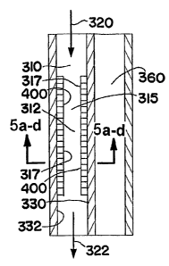
Fig. 5 is a schematic illustration of a repeating unit comprising a process
microchannel and an adjacent heat exchange channel that may be used in the
microchannel reactor core of the microchannel reactor shown in Fig. 2. The
flow
of heat exchange fluid in the heat exchange channel may be co-current or
counter-current relative to the flow of process fluid in the heat exchange
channels. The process microchannel contains a porous catalyst. Figs. 5(a)-5(d)
show cross sections of the process microchannel illustrated in Fig. 5 taken
along
line 5(a-d)-5(a-d) in Fig. 5. Fig. 5(a) shows the catalyst on two interior
walls of
the process microchannel, which is the same as shown in Fig. 5. Fig. 5(b)
shows
an alternate embodiment wherein the catalyst is on one interior wall. Fig.
5(c)
shows another alternate embodiment wherein the catalyst is on three interior
walls. Fig. 5(d) shows another alternate embodiment wherein the catalyst is on
four interior walls of the process microchannel.
Fig. 6 is a schematic illustration of a repeating unit similar to the
repeating
unit illustrated in Fig. 5 except that the repeating unit in Fig. 6 contains a
plurality
CA 02608400 2007-11-13
WO 2006/127889 PCT/US2006/020220
7
of heat exchange channels extending lengthwise at right angles relative to the
lengthwise direction of the process microchannel. The flow of heat exchange
fluid in the heat exchange channels may be cross-current relative to the flow
of
process fluids in the process microchannel.
Fig. 7 is a schematic illustration of a repeating unit that may be used in the
microchannel reactor core of the microchannel reactor shown in Fig. 2. The
repeating unit illustrated in Fig. 7 may be referred to as an integrated
combustion
reactor and comprises at least one reaction chamber and at least one
combustion chamber adjacent to the reaction chamber. The reaction chamber
comprises parallel reaction microchannels containing a porous catalyst, and a
product channel positioned between the reaction microchannels for removing
product from the repeating unit. The reaction microchannels may be referred to
as process microchannels. The reactants flow into the reaction microchannels,
contact the catalyst and react to form one or more products. The products flow
from the reaction microchannels to and through the product channel and then
out
of the repeating unit.
The reaction chamber may be referred to as an
endothermic chamber. The combustion chamber comprises parallel combustion
microchannels and an exhaust microchannel positioned between the parallel
combustion microchannels. A fuel/air mixture flows through the combustion
microchannels, contacts a catalyst within the combustion microchannels and
undergoes a combustion reaction. The exhaust gas resulting from the
combustion reaction flows out of the repeating unit through the exhaust
microchannel. The exhaust microchannel also contains a catalyst for treating
the
exhaust gas. The combustion microchannels and the exhaust gas microchannel
may be referred to as process microchannels. The combustion chamber may be
referred to as an exothermic chamber.
Fig. 8 is a cross-sectional view of the repeating unit illustrated in Fig. 7
taken along line 8-8 in Fig. 7. Fig. 8 shows a plurality of the repeating
units
illustrated in Fig. 7 positioned side-by-side.
Fig. 9 is a schematic illustration of a staged addition repeating unit that
may be used in the microchannel reactor shown in Fig. 2. This repeating unit
comprises a process microchannel, an apertured section, a second reactant
stream channel, and a heat exchange channel. The process microchannel
CA 02608400 2007-11-13
WO 2006/127889 PCT/US2006/020220
8
contains a porous catalyst. The catalyst is positioned in a reaction zone
within
the process microchannel. The process microchannel has a mixing zone
upstream of the reaction zone.
Fig. 10 is a schematic illustration of an alternate embodiment of a staged
addition repeating unit that may be used in the microchannel reactor shown in
Fig. 2. This repeating unit comprises a process microchannel, an apertured
section, a second reactant stream channel, and a heat exchange channel. The
process microchannel contains a porous catalyst. The catalyst is positioned in
a
reaction zone within the process microchannel.
Fig. 11 is a schematic illustration of another alternate embodiment of a
staged addition repeating unit that may be used in the microchannel reactor
shown in Fig. 2. This repeating unit comprises a process microchannel, an
apertured section, a second reactant stream channel, and heat exchange
channel. The process microchannel contains a porous catalyst. The catalyst is
positioned in a reaction zone within the process microchannel. The process
microchannel has a mixing zone upstream of the reaction zone.
Fig. 12 is a scanning electron microscopic (SEM) image of a porous
stainless steel substrate. This substrate may be used for making an apertured
section for the staged addition repeating units illustrated in Fig. 9-11.
Fig. 13 is an SEM image of the substrate illustrated in Fig. 12 except that it
is heat treated. This substrate may be used for making an apertured section
for
the staged addition repeating units illustrated in Figs. 9-11.
Fig. 14 is an SEM image of a tailored porous substrate which may be used
for making an apertured section for the staged addition repeating units
illustrated
in Figs. 9-11.
Fig. 15 is a schematic illustration of a plan view of an apertured sheet
which may be used in making an apertured section for the staged addition
repeating units illustrated in Figs. 9-11.
Fig. 16 is a schematic illustration of a plan view of an apertured sheet or
plate which may be used in making an apertured section for the staged addition
repeating units illustrated in Figs. 9-11.
Fig. 17 is a schematic illustration of a relatively thin apertured sheet
overlying a relatively thick apertured sheet or plate which may be used in
making
CA 02608400 2007-11-13
WO 2006/127889 PCT/US2006/020220
9
an apertured section for the staged addition repeating units illustrated in
Figs. 9-
11.
Fig. 18 is a schematic illustration of a relatively thin apertured sheet
overlying a relatively thick apertured sheet or plate which may be used in
making
an apertured section for the staged addition repeating units illustrated in
Figs. 9-
11.
Fig. 19 is a schematic illustration of an alternate embodiment of an
aperture that may be used in the apertured section of the staged addition
repeating units illustrated in Figs. 9-11. The aperture has a coating
partially filling
it and overlying its sidewalls.
Fig. 20 is a schematic illustration of a repeating unit comprising a process
microchannel and an adjacent heat exchange channel that may be used in the
microchannel reactor illustrated in Fig. 2 or microchannel separator
illustrated in
Fig. 3. The process microchannel contains a porous catalyst or porous sorption
medium on one interior wall and surface features for modifying the flow of
process fluid in the process microchannel on an opposite interior wall. The
surface features are in the form of spherical depressions in the interior wall
of the
process microchannel. The flow of process fluid in the process microchannel is
indicated by the arrows in Fig. 20.
Fig. 21 is a schematic illustration of a repeating unit comprising a process
microchannel and an adjacent heat exchange channel that may be used in the
microchannel reactor illustrated in Fig. 2 or microchannel separator
illustrated in
Fig. 3. The process microchannel contains a porous catalyst or porous sorption
medium on one interior wall and surface features for modifying the flow of
process fluid in the process microchannel on an opposite interior wall. The
surface features are in the form of frustrum depressions in the interior wall
of the
process microchannel. The flow of process fluid in the process microchannel is
indicated by the arrows in Fig. 21.
Fig 22 is a schematic illustration of a repeating unit comprising a process
microchannel and an adjacent heat exchange channel that may be used in the
microchannel reactor illustrated in Fig. 2 or microchannel separator
illustrated in
Fig. 3. The process microchannel contains a porous catalyst or porous sorption
medium on one interior wall and surface features for modifying the flow of
CA 02608400 2007-11-13
WO 2006/127889 PCT/US2006/020220
process fluid in the process microchannel on an opposite interior wall. The
surface features are in the form of angled rectangular depressions in the
interior
wall of the process microchannel. The flow of process fluid in the process
microchannel is indicated by the arrows in Fig. 22.
5 Fig. 23 is a schematic illustration of surface features which may be
used in
microchannels (e.g., process microchannels, second reactant stream
microchannels, heat exchange microchannels) that may be used in the
microchannel reactor illustrated in Fig. 2 or microchannel separator
illustrated in
Fig. 3. The surface features are in the form of spherical depressions in
opposite
10 interior walls of the microchannel.
Fig. 24 is a schematic illustration of surface features which may be used in
microchannels that may be used in the microchannel reactor illustrated in Fig.
2
or microchannel separator illustrated in Fig. 3. The surface features are in
the
form of frustum depressions in opposite interior walls of the microchannel.
Fig. 25 is a schematic illustration of surface features which may be used in
microchannels (e.g., process microchannels, second reactant stream
microchannels, heat exchange microchannels) that may be used in the
microchannel reactor illustrated in Fig. 2 or microchannel separator
illustrated in
Fig. 3. The surface features are in the form of angled rectangular depressions
in
opposite interior walls of the microchannel.
Fig. 26 is a schematic illustration of vanes that may be used as surface
features in microchannels (e.g., process microchannels, second reactant stream
microchannels, heat exchange microchannels) which may be used in the
microchannel reactor illustrated in Fig. 2 or microchannel separator
illustrated in
Fig. 3.
Fig. 27 is a schematic illustration of surface features in the form of air-
foils
that may be used in the microchannels (e.g., process microchannels, second
reactant stream microchannels, heat exchange microchannels) which may be
used in the microchannel reactor illustrated in Fig. 2 or microchannel
separator
illustrated in Fig. 3.
Fig. 28 is a schematic illustration of various surface feature designs that
may be used in the microchannels (e.g., process microchannels, second reactant
stream microchannels, heat exchange microchannels) used in the microchannel
CA 02608400 2007-11-13
WO 2006/127889 PCT/US2006/020220
11
reactor illustrated in Fig. 2 or microchannel separator illustrated in Fig. 3.
Fig. 29 is a schematic illustration of a porous support in the form of a
support strip with a front or first surface and a back or second surface, and
a
plurality of microgrooves formed in each surface. The microgrooves formed in
the front surface are parallel to each other and are positioned in an array of
block
patterns wherein in a first block pattern the microgrooves are aligned in a
first or
horizontal direction and then in a next adjacent second block pattern the
microgrooves are aligned in a second or vertical direction. The array of block
patterns comprises a plurality of block patterns arranged in successive rows
positioned one above another, the successive rows forming a plurality of
columns
positioned side by side one another. The microgrooves formed in the back
surface are also parallel to each other and are positioned in an array of
block
patterns similar to the block patterns in the front surface with the exception
that
where the front surface has microgrooves that are aligned in a first or
horizontal
direction the back surface has microgrooves that are aligned in a second or
vertical direction. Similarly, where the first surface has microgrooves that
are
aligned in a second or vertical direction the back surface has microgrooves
that
are aligned in a first or horizontal direction. The microgrooves in the front
surface
and the microgrooves in the back surface partially penetrate the support
strip.
The penetration of the microgrooves in the front and back surface is
sufficient for
the microgrooves in the front surface to intersect the microgrooves in the
back
surface with the result being the formation of an array of openings in the
support
strip in the regions where the front and back microgrooves intersect. The
resulting openings are of sufficient size to permit a fluid to flow or diffuse
through
the openings.
Fig. 30 is a schematic illustration of a composite porous support structure
comprising a plurality of the porous supports illustrated in Fig. 29
positioned side
by side.
Fig. 31 is a schematic illustration of a porous support comprising a support
strip with a plurality of microgrooves formed in one of its surfaces. The
front
edge, back edge and side edges of the support strip are sufficiently open to
permit fluid to flow through the front, back and side edges.
Fig. 32 is a schematic illustration of a porous support comprising a support
CA 02608400 2007-11-13
WO 2006/127889 PCT/US2006/020220
12
strip with a plurality of microgrooves formed in one of its surfaces. This
support
is similar to the support illustrated in Fig. 31 with the exception that the
front edge
and the back edge of the microgrooved support strip illustrated in Fig. 32 are
closed and thus do not permit fluid to flow through the front and back edges.
Fig. 33 is a schematic illustration of a porous support comprising a support
strip with a plurality of microgrooves formed in one of its surfaces. This
support
is similar to the support illustrated in Fig. 32 with the exception that the
side
edges of the microgrooved support strip illustrated in Fig. 33 are closed and
thus
do not permit fluid to flow through the side edges. The microgrooves may
penetrate part way or all the way through the support strip. Penetration of
the
microgrooves all the way through the support strip may permit fluid to flow
through the microgrooves in the direction from the top surface to the bottom
surface, or vice versa.
Fig. 34 is a schematic illustration of a porous support comprising a plurality
of support strips with a plurality of microgrooves formed in one of the
surfaces of
each support strip. The support strips are positioned side by side one another
forming a composite support structure, the front and back edges of each of the
microgrooved support strips being open sufficiently to permit fluid to flow
through
such edges. The microgrooves in each of the support strips project through the
support strips sufficiently to permit fluid to flow through the support strips
from
one support strip to another.
Fig. 35 is a schematic illustration of an exploded view of the porous
support illustrated in Fig. 34. The porous support illustrated in Fig. 35
comprises
four (4) first microgrooved support strips and four (4) second microgrooved
support strips positioned side by side in alternating sequence. The
microgrooves
in each of the support strips project through the support strips sufficiently
to
permit fluid to flow through the support strips from one support strip to
another.
The first microgrooved support strips employ microgrooves that form angles
with
the center axis of the support strips that are oriented toward the front edges
and
first side edges of the support strips and are more than about 0 and less
than
90 , for example, in the range from about 60 to about 80 . The second
microgrooved support strips employ microgrooves that form angles with the
center axis of the support strips that are oriented toward the front edges and
first
CA 02608400 2007-11-13
WO 2006/127889 PCT/US2006/020220
13
side edges of the support strips and are more than 90 and less than about 180
,
for example, in the range from about 1000 to about 120 .
Fig. 36 is a cross-sectional view of a process microchannel containing the
porous support illustrated in Fig. 34. The porous support illustrated in Fig.
36 is a
flow-through support.
Fig. 37 is a photograph of a porous support comprising a microgrooved
support strip made of an alloy of iron, chromium, aluminum and yttrium, the
thickness of the support structure being 0.002 inch (50.8 microns), the ribs
dividing the microgrooves having a thickness of 0.007 inch (178 microns), and
the microgrooves having a width of 0.007 inch (178 microns).
Fig. 38 is a photograph of a porous support comprising a microgrooved
support strip similar to the support strip illustrated in Fig. 37 with the
exception
that the microgrooved support strip illustrated in Fig. 38 is made of
stainless
steel.
Fig. 39 is a microphotograph enlarged 50X showing a porous support
comprising a microgrooved support strip with catalyst particles deposited in
the
microgrooves of the microgrooved support strip, the microgrooved support strip
being made of stainless steel 304, the catalyst comprising 0.7% K20-15%
Mo03/Si02-Ti02.
Fig. 40 is a photograph of a process microchannel containing two porous
supports of the type shown in Fig. 33. The process microchannel has a length
of
2.5 inches (6.35 cm), a width of 0.5 inch (12.7 mm), and a height of 0.002
inch
(50.8 microns). A top plate for the process microchannel is shown on the right
side of Fig. 40.
Figs. 41-43 are schematic illustrations of microchannel walls with
microgrooved support strips positioned on the walls in combination with
surface
features positioned in or projecting from the walls.
Fig. 44 is an SEM micrograph of a porous support comprising a
macroporous SiCN catalyst support in the form of a three-dimensional
interconnected pore structure containing pores with diameters of about 1
micron
formed by pyrolysis.
Fig. 45 is a schematic illustration showing a two-step process for making a
macroporous alumina or silicon carbide layer which may be used as a porous
CA 02608400 2007-11-13
WO 2006/127889 PCT/US2006/020220
14
support.
Fig. 46 is a schematic illustration showing a one-step process for making a
macroporous alumina or silicon carbide layer which may be used as a porous
support.
Fig. 47 shows SEM micrographs of alumina nanotubes formed using
anodization. The nanotubes may be used to form a porous support. The
micrograph on the left labeled (a) shows the surface morphology of the
anodized
surface as synthesized. The micrograph on the right labeled (b) shows the
surface morphology of the anodized surface after being hydrothermally treated.
The surface area before hydrothermal treatment is about 150 m2/g while the
surface area after hydrothermal treatment is about 1500 m2/g.
Fig. 48 shows SEM micrographs of an annealed TiO2 layer which may be
used as a porous support. The TiO2 layer comprises TiO2 nanotubes. The image
on top labeled "a" is a top view of the nanotube layer. The image on the
bottom
labeled "b" is a cross-sectional view of the nanotube layer. The abbreviation
"nm" is for nanometer.
Fig. 49 is a schematic illustration showing a process for making
platinum/alumina nanofibers which may be used as a porous catalyst.
Fig. 50 shows SEM micrographs of carbon nanotubes grown on FeCrAlY
foam structures. The nanotubes may be used to form a porous support. The
micrograph on the left is at a magnification of 50X. The micrograph on the
right
is at a magnification of 200X.
= Fig. 51 shows SEM micrographs of carbon nanotubes grown on FeCrAlY
foam structures with alumina coatings. The micrograph labeled (a) is at a
magnification of 50X. The micrograph labeled (b) is at a magnification of
1000X.
The micrograph labeled (c) is at a magnification of 10000X.
Fig. 52 is a schematic illustration showing a process for making carbon
nanotubes coated with platinum. These coated nanotubes may be used as a
porous catalyst.
Fig. 53 shows high-resolution transmission electron microscopic (HRTEM)
images of gold particles dispersed on the surface of carbon nanotubes prepared
using electroless plating. The image on the left labeled (a) is at a low
magnification. The image on the right labeled (b) is at a high magnification.
The
CA 02608400 2007-11-13
WO 2006/127889 PCT/US2006/020220
structures disclosed in Fig. 53 may be used as porous catalysts.
Fig. 54 is a schematic illustration of the microchannel reactor used in the
Computational Fluid Dynamics (CFD) modeling simulation disclosed in Example
1.
5 Fig.
55 is a schematic illustration of the model domain used in the CFD
simulation disclosed in Example 1.
Fig. 56 is a schematic illustration of the mesh used in the CFD simulation
disclosed in Example 1.
Fig. 57 is a schematic illustration showing hypothetical catalyst activity
10
distribution in the transverse direction for the CFD simulation disclosed in
Example 1. r is the normalized distance into the structure from the interface
with
the flow-by channel. r = 0: interface with the flow-by channel. r = 1: channel
wall.
Fig. 58 shows catalyst activity distribution in the axial direction (along the
reaction chamber length) for the CFD simulation disclosed in Example 1. l is
the
15 axial
location normalized by the reactor total length. l = 0: the beginning of the
reactor. l = 1: the end of the reactor.
Fig. 59 is a parity plot of SMR reaction methane conversion predicted via
quadratic curve-fit of CFD predictions versus actual CFD predictions for the
conditions of Set 1 in Table 1. SMR refers to methane steam reforming.
Fig. 60 is a plot showing predicted SMR reaction methane fractional
conversion for the conditions of Set 1 in Table 1, with a constant thermal
conductivity of 1.85 W/m-K, and a flow-by gap of 0.05 mm.
Fig. 61 is a plot showing predicted SMR reaction methane fractional
conversion for the conditions of Set 1 in Table 1, with a constant thermal
conductivity of 3 W/m-K, and a flow-by gap of 0.05 mm.
Fig. 62 is a plot showing predicted SMR reaction methane fractional
conversion for the conditions of Set 1 in Table 1, with a constant catalyst
thickness of 0.374 mm, and a flow-by gap of 0.2 mm.
Fig. 63 is a plot showing predicted SMR reaction methane fractional
conversion for the conditions of Set 1 in Table 1, with a constant thermal
conductivity of 1.85 W/m-K, and a catalyst thickness of 0.374 mm.
Fig. 64 is a plot showing predicted heat flux in W/cm2 consumed by the
endothermic methane refoming reaction for the conditions of Set 1 in Table 1,
CA 02608400 2007-11-13
WO 2006/127889 PCT/US2006/020220
16
with a constant thermal conductivity of 1.85 W/m-K, and a catalyst thickness
of
0.374 mm.
Fig. 65 is a plot showing SMR reaction inlet flow per channel in standard
liters per minute (based on a 3:1 methane to steam molar ratio) for the
conditions
of Set 1 in Table 1, with a constant thermal conductivity of 1.85 W/m-K, and a
catalyst thickness of 0.374 mm.
Fig. 66 is a plot showing predicted SMR reaction productivity in standard
liters per minute of methane converted for the conditions of Set 1 in Table 1,
with
a constant thermal conductivity of 1.85 W/m-K, and a catalyst thickness of
0.374
MM.
Fig. 67 is a plot showing CFD predictions of SMR reaction productivity in
standard liters per minute of methane converted and percent methane
conversion for the full set of conditions of Table 2.
Fig. 68 is a plot showing predicted SMR reaction methane fractional
conversion for the conditions of Set 2 in Table 1, with a 0.36 mm flow-by gap,
catalyst on both major walls, and a constant catalyst thickness of 0.127 mm.
Fig. 69 is a plot showing predicted SMR reaction methane fractional
conversion for the conditions of Set 2 in Table 1, with a 0.36 mm flow-by gap,
and a constant catalyst pore tortuosity of 1.
Fig. 70 is a plot showing predicted SMR reaction methane fractional
conversion for the conditions of Set 2 in Table 1, with a 0.36 mm flow-by gap,
and a constant catalyst pore tortuosity of 2.
Fig. 71 is a plot showing predicted SMR reaction methane fractional
conversion for the conditions of Set 2 in Table 1, with a 0.36 mm flow-by gap,
and a constant catalyst pore tortuosity of 10.
Fig. 72 is a plot showing predicted SMR reaction methane fractional
conversion for the conditions of Set 2 in Table 1, with a constant catalyst
thickness of 0.127 mm, and a constant catalyst pore tortuosity of 1.
Fig. 73 is a plot showing predicted SMR reaction methane fractional
conversion for the conditions of Set 2 in Table 1, with a constant catalyst
thickness of 0.127 mm, and a constant catalyst pore tortuosity of 5.
Fig. 74 is a plot showing predicted SMR reaction methane fractional
conversion for the conditions of Set 3 in Table 1, with a constant catalyst
CA 02608400 2007-11-13
WO 2006/127889
PCT/US2006/020220
17
thickness of 0.127 mm, and a constant wall temperature of 850 C
(extrapolated).
Fig. 75 is a plot showing predicted SMR reaction methane fractional
conversion for the conditions of Set 3 in Table 1, with a constant catalyst
thickness of 0.127 mm, and a wall temperature gradient from 650 C at the
inlet
to 850 C at the outlet.
Fig. 76 is a plot showing predicted SMR reaction methane fractional
conversion for the conditions of Set 3 in Table 1, with a constant catalyst
thickness of 0.127 mm, and a flow-by gap of 0.18 mm.
Fig. 77 is a picture which shows high compressive stress in the higher
coefficient of thermal expansion material and high tensile stress in the lower
coefficient of thermal expansion material disclosed in Example 1.
Fig. 78 shows a picture of an intermediate material modeled as having a
modulus of elasticity of 0.01 times that of stainless steel, the stress being
reduced by 57% as disclosed in Example 1.
Fig. 79 is a plot showing predicted SMR reaction approach to equilibrium
methane conversion for the conditions of Set 1 in Table 1, with a constant
thermal conductivity of 0.9 W/m-K, and a catalyst thickness of 0.28 mm.
Fig. 80 is a plot showing predicted SMR reaction approach to equilibrium
methane conversion for the conditions of Set 1 in Table 1, with a constant
thermal conductivity of 1.85 W/m-K, and a flow-by gap of 0.05 mm. The labels
on dots indicate actual CFD simulation predicted percent approach to
equilibrium.
The contours show curve fits for predicted fractional approach to equilibrium.
Fig. 81 is a schematic illustration of a single channel microchannel reactor
for Example 2. Thermocouples are placed in the metal between the reforming
channel and the combustion channels.
Fig. 82 is a plot showing time on stream (TOS) performance for the 90
microsecond case in Example 2 where conversion is shown with the filled
diamonds and selectivity to CO is shown with open circles. At 110 hours TOS an
upset (shown with a vertical line) occurs where the hydrogen fuel is
temporarily
lost to the combustion side of the reactor.
Fig. 83 is a plot of formaldehyde selectivity versus methanol conversion
using a Mo-Fe catalyst for the process disclosed in Example 4.
Fig. 84 is a plot of formaldehyde selectivity versus methanol conversion for
CA 02608400 2007-11-13
WO 2006/127889
PCT/US2006/020220
18
a V-mo catalyst for the process disclosed in Example 5.
Fig. 85 consists of drawings of a body backing plate used in the
microchannel reactor disclosed in Example 7.
Fig. 86 consists of drawings of the body cover plate used in the
microchannel reactor disclosed in Example 7.
Fig. 87 is a schematic illustration of the microchannel reactor disclosed in
Example 7.
Figs. 88-91 disclose four types of surface feature patterns used with the
microgrooved support strips described in Example 5. The patterns are circles
(Fig. 88), horizontal bars (Fig. 89), chevrons (Fig. 90) and zig-zags (Fig.
91).
Fig. 92 is an exploded view of a microgrooved test device without header,
footer or cooling jacket in place. The test device is used in Example 5.
Fig. 93 is a schematic illustration showing the dimensions of the packed
bed microchannel reactor, with quarter model section, disclosed in Example 9.
Fig. 94 is a center line temperature plotted versus position in the bed for
quartz tube case 3 described in Example 9.
Fig. 95 is a plot of styrene selectivity versus ethylbenzene conversion for
the two 0.06 inch gap microchannel cases described in Example 9.
Fig. 96 is a plot of ethylbenzene conversion versus center to wall exotherm
in C for the CFD model showing the quartz tube and 0.06 inch (1.52 mm) gap
microchannel reactor models disclosed in Example 9.
Fig. 97 is a schematic illustration of the test set up for the microchannel
reactor disclosed in Example 7.
Fig. 98 is a plot showing temperature profiles at two locations along the
length of the reactor disclosed in Example 10. The catalyst loading is 6.78 E8
mg-cat/m3. The ethylbenzene to oxygen molar ratio is 2. The temperature is
400 C.
Fig. 99 is a plot of temperature profiles along the length of the reactor
disclosed in Example 10 wherein the temperatures are measured at two
locations. This plot shows temperature profiles for a non-uniform catalyst
activity
distribution.
Fig. 100 is a plot of temperature profiles along the length of the reactor
disclosed in Example 10 wherein a uniform catalyst activity distribution is
used.
CA 02608400 2007-11-13
WO 2006/127889
PCT/US2006/020220
19
Fig. 101 is a plot showing mass fraction of methanol along the length of
the reactor disclosed in Example 11. The catalyst is catalyst A, which is
disclosed in the example. The temperature is 360 C.
Fig. 102 is a plot showing CH20 mass fraction along the length of the
reactor disclosed in Example 11. The catalyst is catalyst A, which is
disclosed in
the example. The temperature is 360 C.
Fig. 103 is a schematic illustration showing heat removal mechanisms for
a catalyst pellet and for a structured wall microchannel. This illustration is
referred to in Example 11.
Fig. 104 is a plot of temperature profiles at two locations along the length
of the reactor disclosed in Example 11. The catalyst is catalyst A, which is
disclosed in the example. The temperature is 360 C.
Fig. 105 is a plot of a temperature profile in the transverse direction for
the
reactor disclosed in Example 11. The catalyst is catalyst A, which is
disclosed in
the example. The abbreviation "SW" refers to structured wall. The profile is
taken at a point 6 inches (15.24 cm) from the beginning of the structured
wall.
Fig. 106 is a plot of temperature distribution for the reactor disclosed in
Example 11. The baseline temperature is 360 C.
Fig. 107 is a plot of the heat flux profile along the reactor wall of the
reactor disclosed in Example 11.
Fig. 108 is a plot of static pressure along the length of the reactor
disclosed in Example 11. The catalyst is catalyst A, which is disclosed in the
example. The temperature is 360 C.
Fig. 109 is a plot of temperature profiles at two locations along the length
of the reactor disclosed in Example 11.
Fig. 110 is a plot of the center line temperature profile along the reactor
length for the packed bed reactor disclosed in Example 11. The catalyst is
catalyst B, which is disclosed in the example.
Fig. 111 is a schematic illustration of the reactor disclosed in Example 13.
Figs. 112-114 are schematic illustrations of a device for evaluating multiple
catalysts on a porous wall within a microchannel reactor. The device is
discussed in Example 14.
Fig. 115 is a schematic illustration of flow-through catalyst support.
CA 02608400 2007-11-13
WO 2006/127889 PCT/US2006/020220
Detailed Description
The term "porous" or "porosity" may refer to a material that is sufficiently
porous to permit fluid to flow or diffuse into and out of the support and/or
flow in
- or through the support.
5 The
term "porous support" may refer to a support structure for a catalyst or
a sorption medium having a pore volume in the range from about 1% to about
99%, and in one embodiment in the range from about 5% to about 98%, and in
one embodiment in the range from about 30% to about 95%. In one
embodiment, at least about 20%, and in one embodiment at least about 50% of
10 the
pore volume may comprise pores in the average size (diameter) range from
about 0.1 to about 700 microns, and in one embodiment from about 0.3 to about
500 microns, and in one embodiment from about 1 to about 200 microns. Pore
volume and pore size distribution may be measured by Mercury porisimetry and
nitrogen adsorption or SEM analysis of the resulting structure.
Mercury
15
porisimetry and nitrogen adsorption are complementary techniques with mercury
porisimetry being more accurate for measuring large pore sizes (larger than
about 30 nm) and nitrogen adsorption more accurate for small pores (less than
about 50 nm). Pore sizes in the range from about 0.1 to about 700 microns may
be of sufficient dimension to enable molecules to diffuse through the porous
20
material using molecular versus Knudsen diffusion. The porosity may be
geometrically regular or geometrically tortuous or random. The porous support
may be thermally conductive. The porous support may comprise a support strip
having a front or first surface and a back or second surface. The support
strip
may comprise a shim. The support strip may be made of a thermally conductive
material. The support strip may have a plurality of microgrooves formed in
either
one or more surfaces of the support strip. The microgrooves may penetrate part
way through or all the way through the support strip. When the microgrooves
are
formed on both sides of the support strip, the microgrooves from one side may
intersect microgrooves from the other side with the result being the formation
of a
plurality of openings or through holes in the support strip. The porous
support
may comprise a single layered microgrooved support strip, or a plurality of
the
microgrooved support strips stacked one above another or positioned side by
side to form a microgrooved composite structure. The plurality of microgrooved
CA 02608400 2007-11-13
WO 2006/127889 PCT/US2006/020220
21
support strips may be connected with a fluid passageway such that a fluid may
flow or diffuse to multiple layers. The fluid passageway may be connected
through all or part of the stack of microgrooved support strips at different
points
along the length of the microgrooved support strips. It may be advantageous to
have a fluidic connection through different portions of the stack of
microgrooved
support strips for different parts of the reactor to tailor the reaction
temperature
profile and resulting conversion, selectivity, and productivity of the
assembled
microchannel reactor. The porous support may comprise a porous thermally
conductive coating layer applied to one or more interior surfaces of a
microchannel. Multiple zones of differing surface area to volume ratio may
exist
within the porous support along the length of the microchannel and along the
depth (or thickness) of the porous support.
The term "porous catalyst" may refer to a catalyst supported by a porous
support. The porous catalyst may be in the form of a flow-by catalyst or a
flow-
through catalyst. The porous support of a porous catalyst may be referred to
as
a first catalyst structure. The active catalyst or active catalytic material
supported
by the porous support may be referred to as a second catalyst structure. The
second catalyst structure may comprise a mesoporous layer, a microporous
layer, or both. The pore size of the mesoporous and microporous layers may be
smaller than the size of the first porous support. Molecules may diffuse via
Knudsen diffusion in the mesoporous and microporous layers. For some
mesoporous layers, the pore size may be intermediate and large enough for
molecular diffusion rather than Knudsen diffusion. In one embodiment, one or
more reactants may flow into or diffuse into the porous catalyst, contact the
active catalyst supported by the porous support, and react to form one or more
products. The one or more products may flow out of or diffuse out of the
porous
catalyst.
The term "porous sorption medium" may refer to a sorption medium
supported by a porous support. In one embodiment, the porous sorption medium
may comprise a sorption medium supported by a porous support wherein the
porous support comprises a single layer comprising a microgrooved or surface
treated support strip.
The term "shim" may refer to a planar or substantially planar sheet or
CA 02608400 2007-11-13
WO 2006/127889 PCT/US2006/020220
22
plate. The thickness of the shim may be the smallest dimension of the shim and
may be up to about 5 mm, and in one embodiment in the range from about 0.01
to about 2 mm, and in one embodiment in the range of about 0.05 to about 1
mm, and in one embodiment in the range from about 0.05 to about 0.5 mm. The
shim may have any length and width.
The term "microchannel" may refer to a channel having at least one
internal dimension of height or width of up to about 10 millimeters (mm), and
in
one embodiment up to about 5 mm, and in one embodiment up to about 2 mm,
and in one embodiment up to about 1 mm. An example of a microchannel that
may be used is illustrated in Fig. 1. Referring to Fig. 1, the illustrated
microchannel has a height (h), width (w) and length (I). Fluid may flow
through
the microchannel in the direction indicated by the arrows. Both the height (h)
and
width (w) are perpendicular to the bulk flow of fluid through the
microchannel.
One of the dimensions of height (h) or width (w) may be in the range from
about
0.05 to about 10 mm, and in one embodiment from about 0.05 to about 5 mm,
and in one embodiment from about 0.05 to about 2 mm, and in one embodiment
from about 0.05 to about 1.5 mm, and in one embodiment from about 0.05 to
about 1 mm, and in one embodiment from about 0.05 to about 0.75 mm, and in
one embodiment from about 0.05 to about 0.5 mm. The other dimension of
height (h) or width (w) may be of any dimension, for example, up to about 3
meters, and in one embodiment from about 0.01 to about 3 meters, and in one
embodiment from about 0.1 to about 3 meters. The length (I) of the
microchannel may be of any dimension, for example, up to about 10 meters, and
in one embodiment from about 0.1 to about 10 meters, and in one embodiment
from about 0.2 to about 10 meters, and in one embodiment from about 0.2 to
about 6 meters, and in one embodiment from 0.2 to about 3 meters. Although
the microchannel illustrated in Fig. 1 has a cross section that is
rectangular, it is
to be understood that the microchannel may have a cross section having any
shape, for example, a square, circle, semi-circle, trapezoid, etc. The shape
and/or size of the cross section of the microchannel may vary over its length.
For
example, the height or width may taper from a relatively large dimension to a
relatively small dimension, or vice versa, over the length of the
microchannel.
The term "process microchannel" may refer to a microchannel containing a
CA 02608400 2007-11-13
WO 2006/127889 PCT/US2006/020220
23
catalyst or a sorption medium. One or more reactants may flow in the process
microchannel, contact the catalyst and react to form one or more products. A
fluid mixture may flow into the process microchannel, contact the sorption
medium, and separate into separate fluid components.
The term "microgroove" may refer to a groove in a substrate having a
depth of up to about 2000 microns, and in one embodiment in the range from
about 1 to about 1000 microns, and in one embodiment in the range from about
1 to about 2000 microns, and in one embodiment in the range from about 1 to
about 500 microns, and in one embodiment in the range from about 1 to about
200 microns, and in one embodiment in the range from about 1 to about 100
microns. The width may be in the range up to about 50 cm, and in one
embodiment in the range from about 0.1 micron to about 50 cm, and in one
embodiment in the range from about 0.1 micron to about 10 cm, and in one
embodiment in the range from about 1 micron to about 1 cm, and in one
embodiment in the range from about 1 to about 1000 microns, and in one
embodiment in the range from about 1 to about 100 microns. The depth may be
measured at the deepest point of penetration into the substrate. The width may
be the width measured at the widest point of the microgroove that is
orthogonal
to the direction of flow. The microgroove may have any length, for example, up
to about 10 cm, and in one embodiment from about 0.1 micron to about 1 cm.
The length may be defined as being parallel to flow. The microgroove may have
a cross section of any shape. These may include square, rectangle, vee, semi-
circle, dovetail and trapezoid. The shape and/or size of the cross section of
the
microgroove may vary over the length of the microgroove. The microgroove may
have a depth, width and length. The width of a vee shaped microgroove may be
measured at the top of the groove and this dimension would be the width of the
microgroove at its widest dimension. The depth of a vee shaped microgroove
may be measured at the bottom of the vee and this would be the deepest point
of
penetration for the vee shaped microgroove. The microgrooves having tapered
sides (e.g., dovetail, trapezoid) may have widths at the bottom of the groove
and
widths at the top of the groove that are different. The widest of these widths
would be the width at its widest dimension.
The term "structured wall" or "SW" may refer to an interior channel wall, for
CA 02608400 2007-11-13
WO 2006/127889 PCT/US2006/020220
24
example, a microchannel wall, with one or more porous supports positioned or
mounted on its surface. A single layer or two or more layers of microgrooved
support strips stacked one above another or positioned side by side may be
positioned or mounted on the channel wall. A catalyst or sorption medium may
be supported by the porous support.
The term "structured wall reactor" may refer to a microchannel reactor
comprising at least one process microchannel wherein the process microchannel
contains one or more structured walls. A catalyst may be supported by the
porous support of the structured wall. A gap may be positioned in the process
io microchannel adjacent the structured wall.
The term "pillar structure" may refer to any porous support which has
substantially the same pattern of solid material and open area extending
through
the entire thickness (smallest dimension) of the porous support.
The term "heat source" may refer to a substance or device that gives off
heat and may be used to heat another substance or device. The heat source
may be in the form of a heat exchange channel having a heat exchange fluid in
it
that transfers heat to another substance or device; the another substance or
device being, for example, a channel that is adjacent to and/or in thermal
contact
with the heat exchange channel. The heat exchange fluid may be in the heat
exchange channel and/or it may flow through the heat exchange channel. The
heat source may be in the form of a non-fluid heating element, for example, an
electric heating element or a resistance heater. The heat source may comprise
an exothermic chemical reaction or a phase changing (i.e., condensing) heat
exchange fluid.
The term "heat sink" may refer to a substance or device that absorbs heat
and may be used to cool another substance or device. The heat sink may be in
the form of a heat exchange channel having a heat exchange fluid in it that
receives heat transferred from another substance or device; the another
substance or device being, for example, a channel that is adjacent to and/or
in
thermal contact with the heat exchange channel. The heat exchange fluid may
be in the heat exchange channel and/or it may flow through the heat exchange
channel. The heat sink may be in the form of a cooling element, for example, a
non-fluid cooling element. The heat sink may be in the form of a Peltier
CA 02608400 2007-11-13
WO 2006/127889 PCT/US2006/020220
electronic element. The heat sink may comprise an endothermic chemical
reaction or a phase changing (i.e., boiling) heat exchange fluid.
The term "heat source and/or heat sink" may refer to a substance or a
device that may give off heat and/or absorb heat. The heat source and/or heat
5 sink
may be in the form of a heat exchange channel having a heat exchange fluid
in it that transfers heat to another substance or device adjacent to and/or in
thermal contact with the heat exchange channel when the another substance or
device is to be heated, or receives heat transferred from the another
substance
or device adjacent to or in thermal contact with the heat exchange channel
when
10 the
another substance or device is to be cooled. The heat exchange channel
functioning as a heat source and/or heat sink may function as a heating
channel
at times and a cooling channel at other times. Part or parts of the heat
exchange
channel may function as a heating channel while another part or parts of the
heat
exchange channel may function as a cooling channel.
15 The
term "heat exchange channel" may refer to a channel having a heat
exchange fluid in it that may give off heat and/or absorb heat. The heat
exchange channel may be a microchannel.
The term "heat exchange fluid" may refer to a fluid that may give off heat
and/or absorb heat.
20 The
term "adjacent" when referring to the position of one channel relative
to the position of another channel may mean directly adjacent such that a wall
separates the two channels. This wall may vary in thickness. However,
"adjacent" channels may not be separated by an intervening channel that would
inhibit heat transfer between the channels. An intervening channel may be
25
included between adjacent channels if it serves as a heat transfer medium
between the two other channels. The term "adjacent" when referring to the
position of a gap or an open space relative to the position of a catalyst or
sorption
medium may mean directly adjacent such that a fluid flowing in the gap or open
space may contact the catalyst or sorption medium. The term "adjacent" also
may include the cases when a non-equal number of mass transfer or reaction
channels and heat exchange channels may be used. For example, two reaction
channels may be next to each other and heat exchange channels may be on the
outside of the two adjacent reaction channels. In one embodiment, three
CA 02608400 2007-11-13
WO 2006/127889 PCT/US2006/020220
26
reactions channels may be adjacent to each other and one or two heat exchange
channels may flank the reaction channels on the outside. In an alternate
embodiment, four, five or more reaction channels may be flanked by one or two
heat exchange channels. These arrangements may be repeated to achieve any
number of channels in a large capacity device.
The term "heat transfer wall" may refer to a common wall between a
process microchannel and an adjacent heat exchange channel where heat
transfers from one channel to the other through the common wall. The heat
transfer wall may have an assembly of one or more microgrooved support strips
or shims in thermal contact to enhance heat transfer in the heat exchange
channel.
The term "thermal contact" may refer to two bodies, for example two
channels, that may not necessarily be in contact with each other or adjacent
to
each other but still may exchange heat with each other. One body in thermal
contact with another body may heat or cool the other body.
The term "fluid" may refer to a gas, a liquid, or a gas or a liquid containing
dispersed solids, or a mixture thereof. The fluid may be in the form of a gas
containing dispersed liquid droplets. The fluid may be in the form of a liquid
containing dispersed gas bubbles.
The term "microchannel reactor" may refer to an apparatus comprising at
least one process microchannel containing at least one porous catalyst. The
catalyst may be a flow-by catalyst or a flow-through catalyst. The catalyst
may
have an adjacent gap or open area forming a bulk flow path for reactants to
flow
in and contact the catalyst. Part or all of the reactants may diffuse into the
porous catalyst and react to form one or more products. The products may
diffuse out of the catalyst back into the bulk flow path and flow out of the
process
microchannel. The microchannel reactor may comprise a plurality of the process
microchannels that may be operated in parallel, a header or manifold assembly
for providing for the flow of fluid into the process microchannels, and a
footer or
manifold assembly providing for the flow of fluid out of the process
microchannels. The microchannel reactor may further comprise at least one heat
source and/or heat sink. The heat source and/or heat sink may comprise one or
more heat exchange channels, for example one or more heat exchange
CA 02608400 2007-11-13
WO 2006/127889 PCT/US2006/020220
27
microchannels, adjacent to and/or in thermal contact with the process
microchannels for cooling and/or heating the fluids in the process
microchannels.
The microchannel reactor may be in the form of a staged addition reactor
wherein second reactant stream channels may be positioned adjacent to the
process microchannels.
The term "ICR" or "integrated combustion reactor" may refer to a reactor
that comprises at least one combustion chamber adjacent to at least one
reaction
chamber. Either or both chambers may comprise one or more microchannels. A
catalyst may be positioned in one or more of the microchannels of the
combustion chamber and/or the reaction chamber. The catalyst in either or both
chambers may be a porous catalyst. The catalyst may have an adjacent gap or
open area forming a bulk flow path for fluid to flow by and contact the
catalyst. A
reactant may enter the microchannel and flow in the bulk flow path in contact
with
the catalyst. When the catalyst is a porous catalyst, part or all of the
reactant
may diffuse into the porous catalyst and react to form one or more products.
The
one or more products may diffuse back into the bulk flow path and flow out of
the
channel.
The term "microchannel separator" may refer to an apparatus comprising
at least one process microchannel containing a porous sorption medium. The
microchannel separator may be used to separate one or more fluids from a fluid
mixture containing the one or more fluids. The microchannel separator may
comprise a plurality of process microchannels that may be operated in
parallel, a
header or manifold assembly for providing for the flow of fluid into the
process
microchannels, and a footer or manifold assembly providing for the flow of
fluid
out of the process microchannels. The microchannel separator may comprise a
heat source and/or heat sink, for example, one or more heat exchange channels,
in thermal contact with the process microchannels for cooling and/or heating
the
contents of the process microchannels. The heat exchange channels may be
microchannels.
The term "surface feature" may refer to a depression in a microchannel
wall and/or a projection from a microchannel wall that modifies flow and/or
mixing
within the microchannel. The surface features may be in the form of circles,
spheres, frustrums, oblongs, squares, rectangles, angled rectangles, checks,
CA 02608400 2007-11-13
WO 2006/127889 PCT/US2006/020220
28
chevrons, vanes, air foils, wavy shapes, and the like. The surface features
may
contain subfeatures where the major walls of the surface features further
contain
smaller surface features that may take the form of notches, waves, indents,
holes, burrs, checks, scallops, and the like. The surface features may have a
depth, a width, and for non-circular surface features a length. Examples are
illustrated in Figs. 20-28 and 41-43. The surface features may be formed on or
in
one or more of the interior walls of a microchannel. The surface features may
be
formed on or adjacent to porous supports, porous catalysts or a porous
sorption
medium. The surface features may be referred to as passive surface features or
passive mixing features. The surface features may be used to disrupt laminar
flow streamlines and create advective flow at an angle to the bulk flow
direction.
This may enhance heat exchange, mass exchange and/or enhance contact
between reactants and catalysts or fluid mixtures and sorption medium.
The term "residence time," which may also be referred to as the "average
residence time," may be the internal volume of a channel occupied by a fluid
flowing through the channel divided by the average volumetric flowrate for the
fluid flowing through the channel at the temperature and pressure being used.
The terms "upstream" and "downstream" may refer to positions within a
channel (e.g., a process microchannel) that is relative to the direction of
flow of a
fluid stream in the channel. For example, a position within the channel not
yet
reached by a portion of a fluid stream flowing toward that position would be
downstream of that portion of the fluid stream. A position within the channel
already passed by a portion of a fluid stream flowing away from that position
would be upstream of that portion of the fluid stream. The terms "upstream"
and
"downstream" do not necessarily refer to a vertical position since the channel
used herein may be oriented horizontally, vertically or at an inclined angle.
The term "sorb" may refer to adsorption and/or absorption.
The terms "standard cubic feet" or "standard cubic meters" may refer to
volumes measured at a temperature of 0 C and atmospheric pressure.
The term "standard liters" or "normal liters" may refer to volumes
measured at a temperature of 0 C and atmospheric pressure.
The term "gauge pressure" may refer to absolute pressure, less
atmospheric pressure. For example, a gauge pressure of zero atmospheres
CA 02608400 2007-11-13
WO 2006/127889 PCT/US2006/020220
29
corresponds to atmospheric pressure. However, throughout the text and in the
appended claims, unless otherwise indicated, all pressures are absolute
pressures.
The term "psi" may refer to pounds per square inch. The term "psig" may
refer to pounds per square inch gauge pressure.
The term "conversion" of a reactant may refer to the change between the
moles or molar flow of the reactant at the inlet (or before reaction) and the
moles
or molar flow of the reactant at the outlet (or in the product after reaction)
divided
by the moles or molar flow of the reactant at the inlet.
The term "cycle" may refer to a single pass of the reactants through the
microchannel reactor.
The term "ml (milliliter) per gram of catalyst per hour" may refer to a
volume (ml) of product produced per gram of catalyst per hour wherein the gram
of catalyst refers to catalytic material in the catalyst but not any support
that may
be present.
The term "yield" may refer to moles of reactant converted to a specific
product divided by the number of moles of reactant converted. The yield may be
calculated by multiplying the conversion of the reactant by the selectivity to
the
product in question.
The term "unit operation" may refer to a unit or apparatus wherein a
chemical reaction, mixing, vaporization, condensation, compression,
separation,
distillation, condensation, heating and/or cooling may be conducted.
The term "bulk flow path" or "bulk flow region" may refer to an open area
or gap within a channel, e.g., a process microchannel. The bulk flow path or
region may be adjacent to a catalyst or a sorption medium. A contiguous bulk
flow path or bulk flow region may allow for rapid fluid flow through the
channel
with a relatively low pressure drop.
The term "equilibrium conversion" may refer to the maximum attainable
conversion of a reactant in an equilibrium limited reaction. The equilibrium
conversion may be a function of reactor temperature, pressure and/or feed
composition. For example, for the case of a hydrocarbon steam reforming
reaction, the equilibrium conversion may increase with increasing temperature
and decrease with increasing pressure.
CA 02608400 2007-11-13
WO 2006/127889 PCT/US2006/020220
The term "reaction chamber" may refer to a chamber wherein a chemical
reaction occurs. The reaction chamber may comprise one or more channels, for
example, one or more process microchannels. The reaction may be an
endothermic reaction or an exothermic reaction.
5 The term "reaction chamber heat flux" may refer to reaction chamber
heat
duty divided by reaction chamber volume. The reaction may be exothermic or
endothermic.
The term "heat exchange chamber" may refer to a chamber that may give
off heat and/or absorb heat. A chemical reaction may occur in the heat
10 exchange chamber. The "heat exchange chamber" may comprise one or more
microchannels. The reaction may be an endothermic reaction or an exothermic
reaction.
The term "average area heat flux" may refer to a reaction chamber heat
duty divided by the area of the reaction chamber heat transfer surface. The
15 reaction chamber heat transfer surface may refer to a planar area, which
may be
intermittent in the case of ribs or other structures in the reaction chamber,
above
which there is area for flow of process fluid and below which there is a wall
that
separates the reaction chamber and an adjacent heat exchange chamber. This
area may form a path for heat transfer between the reaction chamber and the
20 heat exchange chamber. A chemical reaction of opposite thermicity to the
reaction conducted in the reaction chamber may be conducted in the heat
exchange chamber.
The term "heat flux intensity" may refer to the average area heat flux
divided by the absolute value of the average temperature difference across the
25 thickness of the heat transfer wall (in the direction of heat flow),
that is, flux/dT.
The term "mass flux intensity" may refer to the number of moles of
reactant converted per heat transfer surface area.
The term "heat transfer surface area" may refer to the area of a plane that
separates a process microchannel and an adjacent heat exchange channel. The
30 term "heat transfer surface area" may refer to the area of a plane that
separates
an endothermic chamber or channel from an adjacent to exothermic chamber or
channel.
CA 02608400 2007-11-13
WO 2006/127889 PCT/US2006/020220
31
The term "endothermic chamber" or "endothermic channel" may refer to a
chamber or channel with a fluid in the chamber or channel that absorbs heat
from
another chamber or channel in thermal contact with the endothermic chamber or
channel. If an endothermic reaction occurs in the endothermic chamber or
channel, it may be referred to as an "endothermic reaction chamber" or
"endothermic reaction channel."
The term "exothermic chamber" or "exothermic channel" may refer to a
chamber or channel with a fluid in the chamber or channel that transfers heat
to
another chamber or channel in thermal contact with the exothermic chamber or
channel. If an exothermic reaction occurs in the exothermic chamber or
channel,
it may be referred to as an "exothermic reaction chamber" or an "exothermic
reaction channel."
The term "reaction channel" may refer to a channel wherein a chemical
reaction occurs. The reaction channel may be an endothermic reaction channel
or an exothermic reaction channel.
The term "web" may refer to a wall that separates a reaction channel or
chamber and an adjacent heat exchange channel or chamber.
The terms "tortuous" or "tortuosity" may refer to the ratio of the length of a
diffusion path for a fluid flowing through a porous support, porous catalyst
or
porous sorption medium to the thickness of the porous support, porous catalyst
or porous sorption medium. A tortuosity value of 1.0 refers to a straight line
path.
Tortuosity values higher than 1.0 refer to paths that are not straight line
paths. A
tortuosity of 5, for example, implies that the molecules need to diffuse a
length
equal to 5 times the linear or straight line distance between two points.
The term "volume" may refer to the internal volume of a channel (e.g., a
process microchannel). The internal volume may include an open area or gap for
fluid flow that may be adjacent to a catalyst or sorption medium, but may not
include the catalyst or sorption medium volume. The volume may include volume
within surface features that may be positioned in the channel.
The term "open channel" or "flow-by channel" or "open path" may refer to a
channel (e.g., a microchannel) with a gap of at least about 0.01 mm that
extends
all the way through the channel such that fluid may flow through the channel
with
relatively low pressure drop. The gap may extend up to about 10 mm.
CA 02608400 2007-11-13
WO 2006/127889 PCT/US2006/020220
32
The term "contact time" may refer to the volume in an open channel
divided by the volumetric feed rate into the channel at standard conditions.
The term "standard conditions" may refer to a temperature of 0 C and
atmospheric pressure.
The term "space velocity" may refer to the inverse of contact time. That is,
space velocity = 1/CT where CT is contact time.
The term "approach to equilibrium conversion" or "approach to theoretical
conversion" may refer to the measured or predicted conversion in an
equilibrium
limited reaction of a limiting reactant to a desired product divided by the
equilibrium conversion of the limiting reactant to the desired product times
100(Yo.
The term "ultrafast reaction" may refer to a reaction wherein the contact
time is less than about 4 ms, and in one embodiment in the range from about
0.4
to about 4 ms; the heat flux may be greater than about 10 W/cm2, and in one e
embodiment in the range from about 10 to about 100 W/cm2; the pressure drop
may be less than about 15 atmospheres per meter, and in one embodiment less
than about 13.8 atmospheres per meter. In one embodiment, the reaction may
be an equilibrium limited reaction and the approach to equilibrium conversion
may be greater than about 75%.
The term "cross-sectional area" or "an area of a cross-section" of a
channel (e.g., process microchannel) may refer to an area measured
perpendicular to the direction of the bulk flow of fluid in the channel and
may
include all areas within the channel including any catalyst or sorption medium
that may be present (e.g., catalyst particles, catalyst monolith and/or
catalyst wail
coating), but does not include the channel walls. For channels that curve
along
their length, the cross-sectional area may be measured perpendicular to the
direction of bulk flow at a selected point along a line that parallels the
length and
is at the center (by area) of the channel. The term "a cross sectional area
varies"
may mean that there is a significant variation in cross sectional area within
the
channel, not merely a variation in surface roughness of an interior wall
within the
channel. Dimensions of height and width may be measured from one channel
wall to the opposite channel wall. These dimensions may not be changed by
application of a coating to the surface of the wall. These dimensions may be
average values that account for variations caused by surface roughness,
CA 02608400 2007-11-13
WO 2006/127889 PCT/US2006/020220
33
corrugations, and the like.
The term "graded catalyst" may refer to a catalyst with one or more
gradients of catalytic activity. The graded catalyst may have a varying
concentration or surface area of a catalytically active metal. The graded
catalyst
may have a varying turnover rate of catalytically active sites. The graded
catalyst
may have physical properties and/or a form that varies as a function of
distance.
For example, the graded catalyst may have an active metal concentration that
is
relatively low at the entrance to a process microchannel and increases to a
higher concentration near the exit of the process microchannel; or a lower
concentration of catalytically active metal nearer the center (i.e., midpoint)
of a
process microchannel and a higher concentration nearer a process microchannel
wall, etc. The thermal conductivity of a graded catalyst may vary from one
location to another within a process microchannel. The surface area of a
graded
catalyst may be varied by varying size of catalytically active metal sites on
a
constant surface area support, or by varying the surface area of the support
such
as by varying support type or particle size. The graded catalyst may also be
achieved by changing the size of the microgrooves in the microgrooved strips
such that the surface area to volume ratio is higher or lower in different
parts of
the reactor followed by the application of the same catalyst coating
everywhere
or a hybrid combination of the preceding embodiments. The graded catalyst may
have a single catalytic component or multiple catalytic components (for
example,
a bimetallic or trimetallic catalyst). The graded catalyst may change its
properties
and/or composition gradually as a function of distance from one location to
another within a process microchannel. The graded catalyst may comprise
rimmed particles that have "eggshell" distributions of catalytically active
metal
within each particle. The graded catalyst may be graded in the axial direction
along the length of a process microchannel or in the lateral direction. The
graded
catalyst may have different catalyst compositions, different loadings and/or
numbers of active catalytic sites that may vary from one position to another
position within a process microchannel. The number of catalytically active
sites
may be changed by altering the porosity of the catalyst structure. This may be
accomplished using a washcoating process that deposits varying amounts of
catalytic material. An example may be the use of different porous catalyst
CA 02608400 2007-11-13
WO 2006/127889 PCT/US2006/020220
34
thicknesses along the process microchannel length, whereby a thicker porous
structure may be left where more activity is required. A change in porosity
for a
fixed or variable porous catalyst thickness may also be used. A first pore
size
may be used adjacent to an open area or gap for flow and at least one second
pore size may be used adjacent to the process microchannel wall.
The term "mm" may refer to millimeter. The term "nm" may refer to
nanometer. The term "ms" may refer to millisecond. The term "ps" may refer to
microsecond. The term "pm" may refer to micron.
The porous support may be used to support a catalyst in a microchannel
reactor or a sorption medium in a microchannel separator. A microchannel wall
with a porous support on the wall may be referred to as a structured wall
(SW).
An example of a suitable microchannel reactor is illustrated in Fig. 2.
Referring to
Fig. 2, microchannel reactor 100 may include microchannel reactor core 110,
header or manifold assembly 120, and footer or manifold assembly 130. The
microchannel reactor core 110 may comprise a plurality of repeating units that
may be operated in parallel, each repeating unit comprising at least one
process
microchannel. In one embodiment, the microchannel reactor 100 may be a
staged addition reactor and each repeating unit may further comprise at least
one second reactant stream channel positioned adjacent to the process
microchannel. The header or manifold assembly 120 provides for the flow of
reactants into the process microchannels, and in one embodiment the second
reactant stream channels. The footer or manifold assembly 130 provides for the
flow of product out of the process microchannels. The microchannel reactor
core
110 may further comprise a heat source and/or heat sink in thermal contact
with
the process microchannels. The heat source and/or heat sink may comprise one
or more heat exchange channels in thermal contact with the process
microchannels, and in one embodiment the second reactant stream channels.
The heat exchange channels may be microchannels. When the reaction that is
conducted in the process microchannels is an exothermic reaction, the heat
exchange channels may be used to provide cooling to the process
microchannels. When the reaction that is conducted in the process
microchannels is an endothermic reaction, the heat exchange channels may be
used to provide heat to the process microchannels. Various combinations of
CA 02608400 2007-11-13
WO 2006/127889 PCT/US2006/020220
heating and cooling may be employed to provide for desired temperature
profiles
within and along the length of the process microchannels, and in one
embodiment along the length of the second reactant stream channels. Each of
the process microchannels may contain one or more porous catalysts. In
5
operation, two or more reactants may flow into the microchannel reactor core
110
as indicated arrows 122 and 124. The reactants may be mixed upstream of the
microchannel reactor 100, in the header or manifold assembly 120, or in the
process microchannels within the microchannel reactor core 110. Within the
process microchannels, the reactants may be mixed with each other upstream of
10 a
reaction zone containing the catalyst or in the reaction zone containing the
catalyst. The reactants may be mixed partly upstream of the reaction zone
containing the catalyst and partly in the reaction zone. The reactants may
undergo reaction in the process microchannels to form the product. The product
may flow through the footer or manifold assembly 130 and out of the
15
microchannel reactor 100 as indicated by arrow 132. Heat exchange fluid may
enter the microchannel reactor core 110, as indicated by arrow 134, circulate
through heat exchange channels in the microchannel reactor core 110, heat
and/or cool the process microchannels, and flow out of the microchannel
reactor
core 110, as indicated by arrow 136.
20 The
microchannel reactor 100 may be used to conduct any chemical
reaction that may involve one or more fluid reactants and one or more
catalysts.
The reactions that may be conducted may include one or more of the following
reactions: acetylation addition, acylation, alkylation,
dealkylation,
hydrodealkylation, reductive alkylation, amination, ammonia synthesis,
25
aromatization, arylation, autothermal reforming, carbonylation,
decarbonylation,
reductive carbonylation, carboxylation, reductive carboxylation, reductive
coupling, condensation, cracking, hydrocracking,
cyclization,
cyclooligomerization, ammoxidation, water-gas shift, dehalogenation,
dimerization, epoxidation, esterification, Fischer-Tropsch reaction,
halogenation,
30 hydrohalogenation, homologation, hydration, dehydration, hydrogenation,
dehydrogenation, oxidative dehydrogenation,
hydrocarboxylation,
hydroformylation, hydrogenolysis, hydrometallation, hydrosilation, hydrolysis,
hydrotreating, isomerization, methylation, demethylation, metathesis, methanol
CA 02608400 2007-11-13
WO 2006/127889 PCT/US2006/020220
36
synthesis, nitration, oxidation, partial oxidation, polymerization, reduction,
reformation, steam methane reforming reaction, reverse water gas shift,
sulfonation, telomerization, transesterification, dimerizaiton, trimerization,
oligmerization, Sabatier reaction, carbon dioxide reforming, preferential
oxidation,
preferential methanation, or a combination of two or more of the foregoing
reactions.
An endothermic reaction that may be conducted in the microchannel
reactor 100 is steam reforming in which water (steam) and a hydrocarbon (or
hydrocarbons) are reacted to form hydrogen and carbon oxides. A variety of
hydrocarbons may be reformed to produce hydrogen, including methane, ethane,
propane, butane, isobutane, higher alkanes, cyclo-alkanes, alkenes, aromatics,
alcohols, ethers, ketones, and the like including blends and mixtures such as
gasoline, diesel, kerosene, and the like.
In one embodiment, oxidative dehydrogenation may be used to convert
ethylbenzene to styrene.
An example of a microchannel separator that may be used is illustrated in
Fig. 3. Referring to Fig. 3, microchannel separator 200 may include
microchannel separator core 210, header or manifold assembly 220, and footer
or manifold assembly 230. The microchannel separator core 210 may comprise
a plurality of process microchannels that may be operated in parallel. The
header or manifold assembly 220 provides for the flow of fluid into the
process
microchannels. The footer or manifold assembly 230 provides for the flow of
fluid
out of the process microchannels. Heat exchange channels may be used to
provide for the flow of cold heat exchange fluid and hot exchange fluid in the
microchannel separator core 210. Each of the process microchannels may
contain one or more of the porous supports with a sorption medium supported by
the porous support. The microchannel separator may be operated as a
temperature swing adsorption (TSA) device. In operation, a fluid mixture flows
through the header or manifold assembly 220 into the microchannel separator
core 210 as indicated by arrow 222. The fluid mixture flows through the header
or manifold assembly into the process microchannels where it contacts the
porous sorption medium. A cold heat exchange fluid flows through the
microchannel separator core 210 as indicated by arrows 240 and 242 causing
CA 02608400 2012-12-20
91627-65
37
the sorption medium and the fluid in the process microchannel to cool to a
desired cold
temperature. At the desired cold temperature, a first fluid from the fluid
mixture may be
preferentially sorbed by the porous sorption medium. The remaining components
of the
fluid mixture may be removed from the microchannel separator core 210 as
indicated by
arrow 232. The microchannel separator core 210 may then be heated by flowing a
heated
heat exchange fluid through the microchannel separator core 210 as indicated
by arrows
244 and 246. The heating of the microchannel separator core 210 results in the
heating of
the process microchannels and the porous sorption medium. This may cause the
sorbed
first fluid to desorb from the sorption medium. The desorbed first fluid flows
out of the
microchannel separator core 210 as indicated by arrow 234.
The sorption step may be continued until a desired loading of the sorption
medium
by the first fluid is achieved. The desired loading level may be in the range
from about
0.001 to about 1 gram of the first fluid per gram of porous sorption medium,
and in one
embodiment from about 0.01 to about 0.1 gram of the first fluid per gram of
sorption
medium. At the end of this sorption step the non-sorbed parts of the fluid
mixture may be
removed from the process microchannels. During the sorption step, the average
sorbent
temperature within the process microchannels may be in the range from about -
40 C to
about 200 C, and in one embodiment from about -40 C to about 150 C, and in one
embodiment from about 0 C to about 100 C, and in one embodiment about 20 C to
about
60 C, and in one embodiment from about 20 C to about 45 C, and in one
embodiment
about 40 C. The pressure within the process microchannels during the sorption
step may
be in the range from about 0.0001 to about 100 atmospheres of absolute
pressure, and in
one embodiment from about 0.01 to about 50 atmospheres, and in one embodiment
from
about 0.1 to about 30 atmospheres, and in one embodiment from about 1 to about
20
atmospheres, and in one embodiment from about 1 to about 10 atmospheres
absolute
pressure. The period of time for the sorption to occur may be in the range
from about 0.1
to about 10 seconds, and in one embodiment about 1 to about 5 seconds. During
the
desorption step, the temperature within the process microchannels may be
increased
by about 1 C to about 200 C, and in one embodiment from about 5 C to about 50
C,
and in one embodiment from about
CA 02608400 2007-11-13
WO 2006/127889 PCT/US2006/020220
38
C to about 30 C. The time required for performing the desorbing step may be
in the range from about 0.1 to about 10 seconds, and in one embodiment from
about 1 to about 5 seconds.
The microchannel separator 200 may be used to separate any fluid
5
component from any fluid mixture containing the fluid component. Examples of
such separations may include oxygen from air, olefins (e.g., ethylene) from
mixtures of olefins and paraffins (e.g., ethane), and the like.
The fluid
components that may be separated or purified may include oxygen, hydrogen,
nitrogen, NO (e.g., NO, NO2), CO, CO2, H2S, HCN, S02, CH3SCH3, olefins (e.g.,
io
ethylene), paraffins (e.g., ethane), aromatic compounds (e.g., benzene),
isomers,
halogenated compounds (e.g., chlorides), nitrates, sulfates, sugars, esters,
alcohols, ethers, nitro compounds, hydroxyl amines, or mixtures of two or more
thereof. The microchannel separator 200 may be used to separate nitrogen from
methane. The microchannel separator 200 may be used in a process for
upgrading sub-quality methane gas wherein the microchannel separator is used
to separate out nitrogen. The microchannel separator may be used to provide
simultaneous or sequential reaction and separation of one or more reaction
products. The means of separation may include sorption as well as separations
comprising distillation, absorption and/or phase separation.
The microchannel reactor core 110 and microchannel separator core 210
may contain repeating units comprising layers 300 of process microchannels and
layers 350 of heat exchange channels aligned side by side as illustrated in
Fig. 4.
Alternately, the layers 300 and 350 may be stacked one above the other. The
heat exchange channels may be microchannels. For each heat exchange layer
350, one or more process microchannel layers 300 may be used. Thus, for
example, two, three, four, five, six or more process microchannel layers 300
may
be employed with a single heat exchange layer 350. Alternatively, two or more
heat exchange layers 350 may be employed with each process microchannel
layer 300. Process microchannel layer 300 may provide for the flow of process
fluid. Heat exchange channel layer 350 may provide for the flow of heat
exchange fluid. The heat exchange layers 350 may be used for heating and/or
cooling. Each process microchannel layer 300 may be positioned between
adjacent heat exchange microchannel layers 350. Two or more process
CA 02608400 2007-11-13
WO 2006/127889 PCT/US2006/020220
39
microchannel layers 300 may be positioned adjacent to each other to form a
vertically or horizontally oriented stack of process microchannel layers, and
a
heat exchange layer 350 may be positioned on one or both sides of the stack.
Process microchannel layer 300 may contain a plurality of process
microchannels 310 aligned in parallel, each process microchannel 310 extending
along the length of microchannel layer 300 from end 312 to end 314. The
plurality of process microchannels 310 in the layer 300 extend along the width
of
the process microchannel layer 300 from end 316 to end 318. The catalyst or
porous sorption medium may be contained within one or more of the process
microchannels 310. The flow of process fluid through the process microchannels
310 may be in the direction indicated by arrows 320 and 322. Each of the
process microchannels 310 may have a cross section having any shape, for
example, a square, rectangle, circle, semi-circle, etc.
Heat exchange channel layer 350 may contain a plurality of heat
exchange channels 360 aligned in parallel, each heat exchange channel 360
extending along the width of channel layer 350 from end 352 to end 354, the
plurality of heat exchange channels 360 in the channel layer 350 extending
along
the length of channel layer 350 from end 356 to end 358 of channel layer 350.
The heat exchange channels 360 may be microchannels. The heat exchange
fluid may flow through the heat exchange channels 360 in the direction
indicated
by arrows 360 and 362. The flow of heat exchange fluid in the direction
indicated
by arrows 360 and 362 is cross-current to the flow of process fluid flowing
through process microchannels 310, as indicated by arrows 320 and 322.
Alternatively, the heat exchange channels 360 may be oriented to provide for
flow of the heat exchange fluid along the length of the channel layer 350 from
end 356 to end 358, or from end 358 to end 356. This would result in the flow
of
heat exchange fluid in a direction that would be co-current or counter-current
to
the flow of process fluid through the process microchannels 310. Each of the
heat exchange channels 360 may have a cross section having any shape, for
example, a square, rectangle, circle, semi-circle, etc.
The number of channels 310 and 360 in each of the channel layers 300
and 350 may be any desired number, for example, one, two, three, four, five,
six,
eight, ten, hundreds, thousands, tens of thousands, hundreds of thousands,
CA 02608400 2007-11-13
WO 2006/127889 PCT/US2006/020220
millions, etc. Similarly, the number of channel layers 300 and 350 in the
microchannel reactor core 110 or microchannel separator core 210 may be any
desired number, for example, one, two, three, four, six, eight, ten, hundreds,
thousands, etc.
5 The channels 310 and 360 may have rectangular cross sections and be
aligned in side-by-side vertically oriented interleaved planes or horizontally
oriented interleaved stacked planes. These planes may be tilted at an inclined
angle from the horizontal. These configurations may be referred to as parallel
plate configurations. An array of these rectangular channels may be arranged
in
Repeating units that may be used in the microchannel reactor core 110 or
microchannel separator core 210 are illustrated in Figs. 5 and 6. These
repeating units may comprise process microchannel 310 and porous supports
400 positioned in the microchannel. Heat exchange channel 360 is adjacent to
CA 02608400 2007-11-13
WO 2006/127889 PCT/US2006/020220
41
However, some of the process fluid may diffuse into and out of the porous
support in contact with the catalyst or sorption medium. A heat exchange fluid
may flow in the heat exchange channel 360 in a direction that is co-current or
counter-current relative to the flow of process fluid in the process
microchannel
310 (Fig. 5). Alternatively, the heat exchange fluid may flow in the heat
exchange channels 360 in a direction that is cross-current relative to the
flow of
process fluid in the process microchannel 310 (Fig. 6). The process
microchannel wall 330 may be referred to as a heat transfer wall since it is
adjacent to the heat exchange channel 360 (Fig. 5) or channels 360 (Fig. 6).
The microchannel reactor 100 may be in the form of an integrated
combustion reactor (ICR). An example of a repeating unit that may be used in
an
ICR is illustrated in Figs. 7 and 8. Referring to Figs. 7 and 8, the ICR
repeating
unit 150 comprises reaction chamber 160 and combustion chamber 170. These
chambers are adjacent to each other. Either or both chambers may comprise
one or more microchannels. A catalyst 162 may be positioned in process
microchannels in the reaction chamber 160. A catalyst 172 may be positioned in
process microchannels in the combustion chamber 170. The catalyst in at least
one of the chambers is a porous catalyst. The catalyst may have an adjacent
gap or open area forming a bulk flow path for fluid to flow by and contact the
catalyst. A reactant may enter the microchannel and flow in the bulk flow path
in
contact with the catalyst. When the catalyst is a porous catalyst, part or all
of the
reactant may diffuse into the porous catalyst and react to form one or more
products. The one or more products may diffuse back into the bulk flow path
and
flow out of the channel. In one embodiment, the reaction conducted in the
reaction chamber may be an SMR reaction and the catalyst may be a porous
SMR catalyst.
For providing sufficient heat to an endothermic reaction in
the reaction chamber 160, it may be advantageous to employ a reaction in the
combustion chamber 170 that is highly exothermic. Combustion of hydrogen,
CO, or any hydrocarbon or hydrocarbon mixture may be useful.
The microchannel reactor 100 may be a staged addition reactor. The
staged addition reactor may contain a plurality of staged addition repeating
units
in the microchannel reactor core 110. Examples of the staged addition
repeating
units that may be used are illustrated in Figs. 9-11. Referring to Fig. 9,
repeating
CA 02608400 2012-12-20
9'1627-65
42
unit 370 comprises process microchannel 310, heat exchange channel 360, second
reactant stream channel 374, and apertured section 380. A common wall 375
separates
process microchannel 310 and second reactant stream channel 374. The apertured
section 380 is positioned in common wall 375. The process microchannel 310 has
a
mixing zone 311, and a reaction zone 312. The reaction zone 312 includes bulk
flow
region 315. Porous support 400, which supports a catalyst, is positioned in
the reaction
zone 312. The mixing zone 311 is upstream from the reaction zone 312. A first
reactant
flows into process microchannel 310, as indicated by the arrow 320, and into
the mixing
zone 311. A second reactant flows into second reactant stream channel 374, as
indicated
by arrow 376, and from the second reactant stream channel 374 through the
apertured
section 380 into mixing zone 311, as indicated by arrows 382. The direction of
flow of the
second reactant in the second reactant stream channel 374, as indicated by
arrow 376, is
cocurrent with the direction of flow of the first reactant in the process
microchannel 310, as
indicated by arrow 320. Alternatively, the flow of the second reactant in the
second
reactant stream channel 374 may be counter-current or cross-current relative
to the flow of
the first reactant in the process microchannel 310. The first reactant and the
second
reactant contact each other in the mixing zone 311 and form a reactant
mixture. The
reactant mixture flows from the mixing zone 311 into the reaction zone 312,
contacts the
catalyst, and reacts to form the desired product. The product exits the
process
microchannel 310, as indicated by arrow 322. Heat exchange fluid may flow in
the heat
exchange channel in a direction that is co-current, counter-current or cross-
current relative
to the flow of process fluid in the process microchannel 310.
In an alternate embodiment of the repeating unit 370 illustrated in Fig. 9, a
supplemental mixing zone may be provided in the process microchannel 310
between the
mixing zone 311 and the reaction zone 312.
The repeating unit 370A illustrated in Fig. 10 is identical to the repeating
unit 370
illustrated in Fig. 9 with the exception that the repeating unit 370A does not
contain the
separate mixing zone 311. With repeating unit 370A, the second reactant flows
through
the apertured section 380 into the reaction zone 312 where it is mixed with
the first
reactant and reacts to form the desired product. The product then flows out of
the
process microchannel 310, as indicated by
CA 02608400 2007-11-13
WO 2006/127889 PCT/US2006/020220
43
arrow 322.
The repeating unit 370B illustrated in Fig. 11 is identical to the repeating
unit 370 illustrated in Fig. 9 with the exception that part of the second
reactant
mixes with the first reactant in the mixing zone 311, and the remainder of the
second reactant mixes with the first reactant in the reaction zone 312. The
amount of the second reactant that mixes with the first reactant in the mixing
zone 311 may be from about 1% to about 99% by volume of the second reactant,
and in one embodiment from about 5% to about 95% by volume, and in one
embodiment from about 10% to about 90% by volume, and in one embodiment
from about 20% to about 80% by volume, and in one embodiment from about
30% to about 70% by volume, and in one embodiment from about 40% to about
60% by volume of the second reactant. The remainder of the second reactant
mixes with the first reactant in the reaction zone 312.
The porous support 400 may comprise one or more thermally conductive
metals or other thermally conductive materials such as silicon carbide,
graphite,
and the like. Combinations of these may be used. In one embodiment, the
porous support may be characterized by the absence of aluminum metal. In one
embodiment, the porous support may comprise a high surface area alumina
support layer. The porous support may comprise a hybrid or composite structure
that contains multiple layers to provide a structure that is thermally
conductive.
For good thermal transfer the porous support 400 may be positioned on one or
more microchannel walls (see, Figs. 5a to 5d). This may be accomplished by
forming or growing the porous support on the one or more walls of the
microchannel. In one embodiment, a first template may be created to confine
the
porous support to a heat transfer wall of the microchannel. The first template
may comprise fine grooves or slots that are stamped, etched, cut, or otherwise
machined into the heat transfer wall or in an adjacent support strip or shim
that is
subsequently bonded in place to provide good thermal contact. The thickness of
the first template may be in the range from about 0.005 mm to about 2 mm. A
fluid solution of a first templating agent may be allowed to fill the first
template.
The orientation of the first template may be such that draining is minimal.
More
than about 20% of the first template may be filled with the first templating
agent
solution. The first templating agent solution may contain a polymeric material
CA 02608400 2007-11-13
WO 2006/127889 PCT/US2006/020220
44
that is dried in place. A second metallic templating solution may be
introduced
and fill in the interstices or voids provided by the first templating fluid.
The
resulting structure may be heated to high temperatures in an oxidizing
environment such that the polymeric material is removed and a porous metallic
structure is retained that is in intimate contact with the heat transfer wall
of the
microchannel. As the first and second templating fluids are drained from the
microchannel the bulk flow path or open gap may be drained. Capillary forces
may act to retain the templating fluids in any recessed or protruded surface
features that may be present in the microchannel.
The porous support 400 and the heat transfer wall 330 of the
microchannel 310 may comprise a laminate structure. An example of such a
structure may comprise a sheet of sintered metal powder intimately bonded to a
sheet of solid metal. Sheets of sintered metal powder may be commercially
available. Examples may include stainless steel, Inconel and Hastealloy . The
laminate structure may be designed to have the solid sheet to provide
mechanical strength and the porous layer optimized for thermal conductivity. A
porous support that has a high thermal conductivity may be highly advantageous
for high heat-flux applications. The laminate may comprise multiple layers of
porous materials, each layer having a separately specified thickness,
porosity,
pore size and/or thermal conductivity. Metal alloys may be characterized as
having greater mechanical strength than non-alloy metals. However, the thermal
conductivities of metal alloys may be lower than their constituent metals. A
laminate of a porous layer of pure metal on a solid sheet of alloy may be
useful.
Inconel 617, a nickel based alloy, has a thermal conductivity of about 27 W/m-
K
at 900 C. On the other hand, pure nickel has a thermal conductivity of about
75
W/m-K at the same temperature. For a porosity of 50%, the apparent thermal
conductivity of the porous nickel may be about 37 W/m-K. Even at a porosity of
about 70%, the apparent thermal conductivity of the porous nickel may be about
23 W/m-K, which is close to that of solid Inconels 617.
Porous nickel may be formed on Inconel 617 after bonding. One method
may be to conduct a CVD aluminization to cover the Inconel with a layer of
nickel
aluminide. Thickness of the aluminide layer may be in the range up to about
100
microns, and in one embodiment in the range from about 0.1 to about 50
CA 02608400 2007-11-13
WO 2006/127889 PCT/US2006/020220
microns. Leaching with an alkaline solution may be used to remove aluminum
from the aluminide, resulting in a layer of porous nickel. The porosity may be
controlled by controlling the aluminum content in the aluminide. For example,
beta nickel aluminide (NiAl) may lead to a porosity of about 50% with the
5 aluminum leached out. Gamma prime nickel aluminide (Ni3A1) may lead to a
porosity of about 25%. Partial leaching may be used to control porosity. For
example, a thermally conductive layer having a porosity of about 50% or less
may be obtained. The catalyst layer may have a porosity decreasing as a
function of distance from the interface with the open gap.
lo For alloys that are characterized by a small amount of or the absence of
nickel, a porous nickel layer may still be possible. This may be accomplished
by
plating the alloy with a layer of nickel before bonding. Alternatively, the
alloy
surface may be plated after bonding, for example, by using electroless
plating.
CVD aluminization and alkaline leaching may be performed to form the porous
15 nickel layer.
Metals of high thermal conductivities in addition to nickel that may be used
may include silver, copper, gold, chromium and aluminum. The foregoing
methods of forming porous articles may be used with these metals.
The thickness of the porous catalyst may range up to about 10 mm, and in
20 one embodiment from about 10 microns to about 10 mm, and in one
embodiment
from about 50 microns to about 5 mm, and in one embodiment from about 50
microns to about 2 mm, and in one embodiment from about 50 microns to about
1 mm, and in one embodiment from about 50 microns to about 0.5 mm. The
thermal conductivity of the porous catalyst may be in the range from about 0.5
25 W/m-K to about 500 W/m-K.
An open gap for flow may be positioned adjacent to the porous wall of the
porous catalyst. In one embodiment, the gap may be positioned between two
porous walls such that the mean diffusion length of reactants to the catalyst
structure may be one-half the height of the open flow gap. The open flow gap
30 may have a height in the range from about 25 microns to about 5000
microns.
Flow may be convectively enhanced to transport from the open flow passage to
the porous catalyst layer if surface features are used as an intervening layer
between the open flow passage way and the porous catalyst on at least one side
CA 02608400 2007-11-13
WO 2006/127889 PCT/US2006/020220
46
or portion of the microchannel reactor. In one embodiment, a surface feature
layer may be disposed on two sides of the open flow passageway and porous
catalysts may be disposed beneath the surface feature wall and be in thermal
contact with the heat transfer wall.
The non-porous wall may be made of a metal or other thermally
conductive material. The thickness may be determined in part by mechanical
and structural requirements of the design which may be dictated by the
operating
temperatures and/or pressures. Thinner walls may be used in combination with
support ribs and/or other structures that may be used to reinforce the thin
wall
against high differential pressures.
The porous support may be in the form of a support strip or shim with
microgrooves formed in both the front or first surface and the back or second
surface of the strip or shim. These microgrooves may intersect to form a
plurality
of through holes or openings in the support strip. Examples are illustrated in
Figs. 29 and 30. Fig. 29 illustrates porous support 401 which comprises a
support strip or shim 410 which has a front or first surface 412 and a back or
second surface 414, and a plurality of microgrooves 430 formed in each
surface.
The microgrooves 430 formed in the front surface 412 are parallel to each
other
and are positioned in an array of block patterns 450 wherein in a first block
pattern 450 the microgrooves are aligned in a first or horizontal direction
and then
in an adjacent second block pattern 450 the microgrooves are aligned in a
second or vertical direction. The array of block patterns 450 comprises a
plurality
of block patterns 450 arranged in successive rows positioned one above
another,
the successive rows forming a plurality of columns positioned side by side one
another. The microgrooves 430 formed in the back surface 414 are also parallel
to each other and are positioned in an array of block patterns 450 similar to
the
block patterns 450 in the front surface 412 with the exception that where the
front
surface 412 has microgrooves that are aligned in a first or horizontal
direction the
back surface 414 has microgrooves 430 that are aligned in a second or vertical
direction. Similarly, where the front surface 412 has microgrooves 430 that
are
aligned in a second or vertical direction the back surface 414 has
microgrooves
that are aligned in a first or horizontal direction. The microgrooves 430 in
the
front surface 412 and the microgrooves 430 in the back surface 414 partially
CA 02608400 2012-12-20
91627-65
47
penetrate the support strip 410. The penetration of the microgrooves 430 in
the front
and back surface is sufficient for the microgrooves 430 in the front surface
412 to
intersect the microgrooves 430 in the back surface 414 with the result being
the
formation of an array of through holes or openings 452 in the support strip
410 at the
points where the microgrooves intersect. The openings 452 may be of sufficient
size
to permit a fluid to flow or diffuse through the openings 452. The number of
openings
may range from about 1 to about 200,000 openings per cm2, and in one
embodiment
from about 10 to about 100,000 openings per cm2. The openings 452 may have
average dimensions (e.g., diameter) in the range from about 1 to about 2000
microns,
to and in one embodiment from about 10 to about 1000 microns. The block
patterns 450
may have the dimensions of about 0.01 by about 500 mm, and in one embodiment
about 0.5 by about 20 mm. The separation 453 between each block pattern 450
and
the next adjacent block pattern may be in the range from about 0.01 to about
10 mm,
and in one embodiment about 0.1 to about 1 mm. In this embodiment, the pattern
is
alternated in an A, B, A, B fashion. In an alternate embodiment the geometry
may be
varied such that the surface area to volume of the structure may be different
along the
length of the reactor or in different zones of the reactor to accommodate the
reaction
kinetics. By this manner a reaction with a very high rate of heat release near
the top of
the reactor may be advantaged by the use of a structure with a higher surface
area to
volume near the middle or end of the reactor where the kinetics are slower and
the
rate of heat transfer lower. The resulting heat generation rate along the
reactor length
or heat flux profile along the reactor length may be made more even or
uniform. The
pattern may be further optimized to maximize selectivity to the desired
reaction
products. The pattern may also be optimized to create a tailored gradient
within the
catalyst structure, along the length of the catalyst structure or both.
Fig. 30 illustrates a composite porous support structure 402 comprising a
plurality of the porous supports 401 illustrated in Fig. 29 positioned side by
side.
Alternatively, the porous supports 401 may be stacked one above another. Any
number of the porous supports 401 may be stacked one above the other or
positioned
side by side int he composite support structure 402. For example, 2, 3, 4, 6,
8, 10, 20,
30, 50, 100, etc., porous supports 401 may be stacked one
CA 02608400 2007-11-13
WO 2006/127889 PCT/US2006/020220
48
above another or positioned side by side.
The porous support may be in the form of a microgrooved support strip or
shim wherein microgrooves are formed on one side of the support strip or shim.
The microgrooves may be parallel to each other. Examples are shown in Figs.
31-40. Referring to Fig. 31, microgrooved support strip 403 comprises support
strip 410 which is rectangular in shape and has a length (l), width (w) and
thickness (t). The support strip 410 may be a shim. The support strip 410 has
a
first or top surface 412, a second or bottom surface 414, a first side edge
416, a
second side edge 418, a front edge 420 and a back edge 422. The support strip
410 has a center axis 424 extending along the length (l) of the support strip.
A
plurality of parallel microgrooves 430 are formed in the first surface 412. A
first
group 432 of parallel microgrooves 430 extends from the first side edge 416 of
the support strip 410 to the second side edge 418. A second group 434 of the
microgrooves 430 extends from the front edge 420 to the second side edge 418.
A third group 436 of the microgrooves 430 extends from the first side edge 416
of
the support strip 410 to the back edge 422. The microgrooves 430 are oriented
at an angle 425 relative to the center axis 424 that is sufficient to permit
fluid to
flow in the microgrooves 430 in a general direction from the front edge 420
toward the back edge 422 or from the back edge 422 toward the front edge 420.
The front edge 420, back edge 422 and side edges 416 and 418 of the
microgrooved support strip 401 are open. That is, the microgrooves 430 have
open ends that project through the front edge 420, back edge 422 and side
edges 416 and 418. These open ends may permit the flow of fluid through the
front edge, back edge and side edges. Each of the microgrooves 430 may be
oriented toward the front edge 420 and the first side edge 416 and forms an
angle 425 with the center axis 424 that is sufficient to permit fluid to flow
in the
microgrooves in a direction toward the second side edge 418 and back edge 422.
The angle 425 may be more than about 0 and less than 90 . The angle 425
may be in the range from about 50 to about 80 , and in one embodiment from
about 60 to about 75 .
The microgrooved support strip 403A illustrated in Fig. 32 is the same as
the microgrooved support strip 403 illustrated in Fig. 31 with the exception
that
the second group 434 of microgrooves 430 and third group 436 of microgrooves
CA 02608400 2007-11-13
WO 2006/127889 PCT/US2006/020220
49
430 that are present in the microgroove support strip 403 are not present in
the
microgrooved support strip 403A. The microgrooved support strip 403A includes
non-grooved sections 434a and 436a which provide the microgrooved support
strip 403A with a front edge 420 and a back edge 422 that are closed. That is,
the front edge 420 and the back edge 422 of the microgrooved support strip
403A are sufficiently blocked to prevent fluid from flowing through the front
edge
420 and back edge 422.
The microgrooved support strip 403A is also shown in Figs. 37 and 38.
Fig. 37 is a photograph of a microgrooved support structure made of an alloy
of
iron, chromium, aluminum and yttrium, the thickness of the support structure
being 0.002 inch (50.8 microns), the ribs dividing the microgrooves having a
thickness of 0.007 inch (178 microns), and the microgrooves having a width of
0.007 inch (178 microns). Fig. 38 is a photograph of a microgrooved support
structure similar to the support structure illustrated in Fig. 37 with the
exception
that the microgrooved support structure illustrated in Fig. 38 is made of
stainless
steel.
The microgrooved support strip 403B illustrated in Fig. 33 is the same as
the microgrooved support strip 403A illustrated in Fig. 32 with the exception
that
the side edges 416 and 418 in the microgrooved support strip 403B are closed
The microgrooves 430 extend between the sides 416 and 418 but not through
the side edges. Thus, the flow of fluid through the side edges 416 and 418 may
be blocked. Also, the microgrooves 430 may penetrate part way or all the way
through the support strip 410. Penetration of the microgrooves 430 all the way
through the support strip 410 may be sufficient to permit fluid to flow
through the
support strip 410 from the top surface 412 to the bottom surface 414, or vice
versa.
The microgrooved support strip 403B may be used as flow-through and/or
flow-by support structure in a microchannel. Microgrooved support strips 403
and 403A may be used as a flow by support structures in a microchannel.
In one embodiment, a plurality of the microgrooved support strips may be
stacked one above another or positioned side by side to form the composite
support structure 404 illustrated in Figs. 34-36. Referring to Figs. 34 and
35,
each of the support strips 403C and 403D have an open front edge 420 and an
CA 02608400 2007-11-13
WO 2006/127889 PCT/US2006/020220
open back edge 422, closed side edges 416 and 418, and microgrooves 430 that
penetrate all the way through the support strip 410 from the top surface 412
to
the bottom surface 414. The open front edges 420, back edges 422 and
microgrooves 430 permit fluid to flow through the microgrooved support strips
5 from one support strip to another support strip within the composite
support
structure as the fluid flows through the composite support structure. The
number
of microgrooved support strips employed in such a composite support structure
may be of any number, for example up to about 50, and in one embodiment up to
about 30, and in one embodiment up to about 15, and in one embodiment up to
10 about 10. The composite support structure may also include end plates to
prevent fluid from flowing out of the sides of the composite support
structure.
The composite support structure 404 illustrated in Figs. 34 and 35
comprises eight (8) microgrooved support strips, four each of microgrooved
support strips 403C and 403D positioned side by side in alternating sequence
'15 and two end plates 409 (only one end plate is shown in Figs. 34 and
35). The
microgrooved support strips 403C and 403D each comprise support strip 410
which is rectangular in shape and has a length, width and thickness. The
support
strip 410 has a center axis extending along the length of the support strip. A
plurality of parallel microgrooves 430 are formed in the support strip 410 and
20 project through the support strip from the top surface 412 to the bottom
surface
414. The open front 420 and back edges 422 and the open microgrooves 430
permit fluid to flow from one microgrooved support strip to another within the
composite support structure 404. A first group of parallel microgrooves
extends
from the first side edge 416 of the support strip 410 to the second side edge
418.
25 A second group of the microgrooves 430 extends from the front edge 420
to the
second side edge 418. A third group of the microgrooves 430 extends from the
first side edge 416 of the support strip 410 to the back edge 422. The front
edge
420 and the back edge 422 are open sufficiently to permit fluid to flow
through
these edges. The side edges 416 and 418 are closed and do not permit fluid to
30 flow through these edges. The microgrooves 430 extend to the side edges
416
and 418 but do not project through these side edges. The end plates 409
prevent fluid from flowing out of the sides of the composite support structure
404.
The microgrooves 430 in the support strips 403C are oriented at an angle
relative
CA 02608400 2007-11-13
WO 2006/127889 PCT/US2006/020220
51
to the center axis of the support strip and the side edge 416 that is more
than 900
and less than 1800, and in one embodiment in the range from about 1000 to
about 1500. The microgrooves 430 in the support strip 403D are oriented at an
angle relative to the center axis of the support strip and the side edge 416
that is
more than 00 and less than 900, and in one embodiment in the range from about
500 to about 800. Fluid flows through the composite structure 404 by entering
the
front edge 420 of the support strips 403C and 403D, flowing through the
microgrooves 430, and transferring from the microgrooves 430 in one support
strip (403C or 403D) to the microgrooves 430 in another support (403C or 403D)
until the fluid reaches the back edge 422 of the support strips and then flows
out
of composite support structure 403. Fig. 35 shows an example of a flow path
through the composite support structure 404 for a fluid entering opening 'A'
of the
composite support structure illustrated in Fig. 34. The flow of fluid through
the
composite support structure 404 may be described as permeating, diffusing and
advecting from one layer to another until the fluid passes from the front end
of
the composite support structure to the back end.
The composite support structure 404 may be a flow-through structure and
fill the cross-section of the process microchannel 310 as illustrated in Fig.
36.
Alternatively, the composite support structure may fill only part of the cross-
section of the process microchannel and a gap may be positioned adjacent the
composite support structure 404 to permit bulk flow in the process
microchannel.
The microgrooves 430 may have cross-sections in the form of squares.
Alternatively, each of the microgrooves 430 may have a rectangular cross-
section, a vee shaped cross-section, a semi-circular cross-section, a dovetail
shaped cross-section, or a trapezoid shaped cross-section. Those skilled in
the
art will recognize that microgrooves with other cross-sectional shapes may be
used in place of the foregoing. Each of the microgrooves 430 has a depth,
width
and length. The depth of each of the microgrooves 430 may be in the range up
to about 1000 microns, and in one embodiment from about 0.1 to about 1000
microns, and in one embodiment in the range from about 1 to about 500 microns,
and in one embodiment in the range from about 1 to about 200 microns, and in
one embodiment in the range from about 1 to about 100 microns. The width,
which would be the width at its widest dimension, for each of the microgrooves
CA 02608400 2007-11-13
WO 2006/127889 PCT/US2006/020220
52
430 may be in the range up to about 1000 microns, and in one embodiment from
about 0.1 to about 1000 microns, and in one embodiment in the range from
about 1 to about 500 microns, and in one embodiment in the range from about 1
to about 200 microns, and in one embodiment in the range from about 1 to about
100 microns. The length of each of the microgrooves 430 may be of any
dimension which depends upon the width of the support strip 410. The length of
each microgroove 430 may be in the range up to about 10 cm, and in one
embodiment from about 0.1 to about 10 cm. The spacing between the
microgrooves may be in the range up to about 1000 microns, and in one
embodiment in the range from about 0.1 to about 1000 microns, and in one
embodiment in the range from about 1 to about 500 microns, and in one
embodiment in the range from about 1 to about 200 microns, and in one
embodiment in the range from about 1 to about 100 microns. The microgrooves
may be formed in the support strip 410 using any suitable technique, including
photochemical machining, laser etching, water jet machining, and the like.
The support strip or shim 410 may have a thickness in the range from
about 0.1 to about 5000 microns, and in one embodiment from about 1 to about
1000 microns, and in one embodiment in the range from about 1 to about 500
microns, and in one embodiment in the range from about 1 to about 200 microns,
and in one embodiment in the range from about 50 to about 150 microns. The
support strip 410 may have any width and any length, the width and length
depending upon the dimensions of the microchannel for which the support strip
410 is to be used. The support strip 410 may have a width in the range from
about 0.01 to about 100 cm, and in one embodiment from about 0.1 to about 10
cm. The length of the support strip 410 may be in the range of about 0.01 to
about 100 cm, and in one embodiment from about 0.1 to about 10 cm. The
support strip 410 as illustrated is in the form of a rectangle. However, it is
to be
understood that the support strip 410 may have any configuration, for example,
square, circle, oval, etc., to conform to the design of the microchannel for
which it
iS to be used.
The support strip or shim 410 may contain surface features as discussed
in greater detail below. These surface features may have subfeatures within
the
main features that are smaller in size. There may be multiple sizes of surface
CA 02608400 2007-11-13
WO 2006/127889 PCT/US2006/020220
53
features on the same microgrooved support strip. There may be different sized
features on different microgrooved sheets that when assembled make a stack of
varying sized surface features into the depth of the stack of microgrooved
support strips.
The support strip or shim 410 may be made of any material that provides
sufficient strength, dimensional stability and heat transfer characteristics
to permit
the use of the porous support 400 in a microchannel for supporting a catalyst
or a
sorption medium. The support strip may be thermally conductive. The support
strip 410 may be made of a thermally conductive material such as a metal,
silicon
carbide, graphite or a combination of two or more thereof. The metal may
comprise steel, aluminum, titanium, nickel, platinum, rhodium, copper,
chromium,
brass, or an alloy of any of the foregoing metals. The support strip 410 may
be
made of stainless steel or an alloy comprising iron, chromium, aluminum and
yttrium.
The porous support 400 may comprise one or more porous thermally
conductive treatment or coating layers formed on one or more interior walls of
the
process microchannel 310. This coating layer may comprise a macroporous
layer having an average pore size in the range from about 50 nm to about 10
microns, and in one embodiment in the range from about 50 nm to about 1
micron; a mesoporous layer having an average pore size in the range from about
2 to about 50 nm; or a microporous layer having an average pore size in the
range up to about 2 nm, and in one embodiment in the range from about 0.1 to
about 2 nm. The macroporous layer may comprise one or more metal oxides or
mixtures of one or more metal oxides with one or more catalytic materials. The
macroporous layer may comprise polymer templated cellular A1203, 1102, SiO2,
SiC, Zr02, or SiCN. The mesoporous layer may comprise sol gel deposited A1203
or Ti02, surfactant templated Si02, anodized A1203 or TiO2 nanotubes, or
multiwall nanotubes (e.g., multiwall carbon nanotubes). The microporous layer
may comprise single wall nanotubes, sol-gel Si02 or zeolites. This treatment
or
coating layer may have a thickness in the range from about 1 micron to about 1
mm, and in one embodiment from about 1 micron to about 0.5 mm. This
treatment or coating layer may have a surface area in the range from about 1
to
about 4000 m2/m3, and in one embodiment from about 50 to about 1000 m2/m3.
CA 02608400 2007-11-13
WO 2006/127889 PCT/US2006/020220
54
The macroporous layer may be formed using a sacrificial organic template
and a colloidal precursor. The macroporous support layer may comprise
interconnected spherical pores in the range from about of 50 nm to about 10
pm,
and in one embodiment in the range from about 50 nm to about 1 pm. The layer
may be deposited on one or more of the interior walls of the microchannel. The
synthesis procedure may be carried out either before or after the strips or
shims
are stacked or bonded together to form the microchannel. The thickness of the
microporous layer may be in the range of about 1 to about 20 pm, depending on
the size of the pores. The surface enhancement factor to a smooth channel
surface may be in the range of about 10 to about 1000 times, depending on the
size of the pores and the thickness of the layer. The porosity of the
macroporous
layer may be in the range of about 50% to about 90%. The macroporous layer
may be made from various materials including metals, e.g. nickel or copper as
well as oxides, such as silica, alumina, zirconia, and titania. Active
catalysts may
'15 be integrated on to the skeletal surface of the structure by
electroless plating or
wet-impregnation.
Alumina or titania nanotubes may be grown from an aluminum or titanium
surface respectively by anodic oxidation in oxalic, phosphoric, or sulfuric
acid.
Synthesis may be carried out before the strips or the shims are bonded. The
internal diameter of the nanotubes may be in the range from about 50 nm to
about 500 nm, depending on the acid concentration and applied voltage. The
height of the nanotubes, which may also be the thickness of the layer, may be
in
the range up to about 100 pm. This may be controlled by anodization time. The
porosity of the nanotube layer may be in the range from about 20% to about
50%. The surface area enhancement factor to a smooth surface may be in the
range fro m 1 to about 1000, depending on the internal diameter of the
nanotubes and the thickness of the layer. Active catalysts may be deposited
into
the nanotubes by electroless plating or wet-impregnation. Metal (platinum,
silver,
etc.) nanowires may be grown in the nanotubes from the underneath aluminum
or titanium surface by electroplating.
Multiwalled carbon nanotubes may be grown on a surface which is coated
with iron catalyst supported on silica. The synthesis procedure may be carried
out either before or after the strips or shims are stacked or bonded to form
the
CA 02608400 2007-11-13
WO 2006/127889 PCT/US2006/020220
microchannel. The diameter of the carbon nanotubes may be in the range from
about 50 to about 80 nm and the length may be up to about 100 pm. The
surface area enhancement factor to a smooth surface may be in the range from
about 1 to about 1000, depending on the length of the nanotubes. This may also
5 be the thickness of the layer. Active metal catalysts may be electroless
plated on
the carbon nanotubes as nanoparticles or wet-impregnated onto the carbon
nanotube layer.
The porous support 400 may comprise a macroporous silicon carbonitride
(SiCN) or silicon carbide (SIC) treatment layer formed on one or more interior
10 walls of the porous microchannel 310. These macroporous layers may have
average pore sizes in the range from about 50 nm to about 1 micron, and
average surface areas in the range from about 105 to about 108 m2/m3. These
macroporous layers may be formed by capillary filling packed beds of
polystyrene
or silica spheres with a low-viscosity preceramic polymer based liquid (e.g.,
15 polyvinylsilazane or alkylhydridopolycarbosilane), curing the preceramic
polymer,
pyrolyzing the cured preceramic polymer, and removing the polystyrene or
silica
spheres to provide the macroporous SiCN or SiC structure. An SiCN structure
that may be prepared by this method is shown in Fig. 44.
A two step process for forming a high-surface area, macroporous layer of
20 A1203, which may be used as the porous support 400, is illustrated in
Fig. 45.
The macroporous layer may have an average pore size in the range from about
50 nm to about 1 micron. The macroporous layer may be formed on one or more
interior walls of the process microchannel 310. The process may comprise
assembling polystyrene microspheres (average diameter of about 200 nm) on
25 one or more of the process microchannel walls, infiltrating the channel
with an
AlOOH sol or an organosilane, drying the channel contents, and then heat
treating the channel in an oxidizing environment such as air at a temperature
sufficiently high to oxidize the polystyrene microspheres, leaving behind a
porous
high surface area A1203 structure. Alternatively, a one-step process, as
30 illustrated in Fig. 46, wherein the channel walls are washcoated with
AlOOH sol
or an organosilane in combination with one or more sacrificial fillers (e.g.,
cellulose, starch gel, protein powder, emulsion). The washcoated microchannel
may be calcined to drive off the sacrificial filler and thereby provide the
CA 02608400 2007-11-13
WO 2006/127889 PCT/US2006/020220
56
macroporous A1203 layer.
The porous support 400 may comprise a mesoporous A1203 treatment
layer that is applied to one or more of the walls of the process microchannel
310
using annodization. The average pore size of this mesoporous layer may be in
the range from about 2 to about 50 nm. The mesoporous layer may be in the
form of A1203 nanotubes as shown in Fig. 47. The A1203 layer may be formed by
annodizing an aluminum alloy shim (e.g., aluminum alloy 1100) in oxalic acid.
The annodization potential may be in the range from about 30 to about 60
volts.
The oxalic acid concentration may be in the range from about 0.2 to about 0.6
M.
The anodized layer may be hydrothermally treated to increase the surface area.
Fig. 47 shows SEM micrographs of alumina nanotubes formed using this
process. The micrograph on the left labeled (a) shows the surface morphology
of
the anodized surface as synthesized. The micrograph on the right labeled (b)
shows the surface morphology of the anodized surface after being
hydrothermally treated. The surface area before hydrothermal treatment may be
about 15 m2/g while the surface area after hydrothermal treatment may be about
150 m2/g.
The mesoporous A1203 treatment layer may be electroplated with Pt to
form a porous catalyst comprising Pt/ A1203 nanofibers. This is schematically
illustrated in Fig. 49.
The porous support 400 may comprise a mesoporous TiO2 treatment or
coating layer that is applied to one or more of the walls of the process
microchannel 310 using annodization. The average pore size of this mesoporous
layer may be in the range from about 2 to about 50 nm. The mesoporous layer
may be in the form of TiO2 nanotubes as shown in Fig. 48. The TiO2 nanotube
layer may comprise individual tubes with diameters of about 100 nm, lengths of
about 500 nm and wall thicknesses of about 15 nm. The TiO2 layer may be
formed by annodizing a titanium sheet in an acidic solution containing
sulfuric
acid and hydrofluoric acid. The annodization potential may be about 20 volts.
The annodized layer may be annealed to provide the mesoporous TiO2 layer.
The porous support 400 may comprise a mesoporous layer comprising
carbon nanotubes formed on one or more interior walls of the process
microchannel 310 by the catalytic decomposition of ethylene. The nanotubes
CA 02608400 2007-11-13
WO 2006/127889 PCT/US2006/020220
57
may be in the form of aligned multiwalled carbon nanotube arrays as shown in
Figs. 50 and 51. This support layer may have an average pore size in the range
from about 2 to about 50 nm. This support layer may be formed on a suitable
substrate, for example an FeCrAIY alloy substrate using the process shown in
Fig. 52. The process may involve first forming a native aluminum oxide layer
on
the substrate, then forming a dense aluminum oxide layer over the native
aluminum oxide layer using metal-organic chemical vapor deposition at a
temperature of about 900 C. Aluminum isopropoxide may be used as a
precursor. The alumina coated substrate may then be dipped in a precursor sol
of Fe/Si02, followed by drying and then calcining at about 450 C for about 2
hours to form a 1 to 2 micron thick film of supported iron oxide nanoparticles
over
mesoporous Si02. The coated substrate may then be heated to about 700 C
under nitrogen in a quartz reactor at atmospheric pressure. Ethylene gas may
be
added to the reactor. The reactor may be cooled to about 450 C. Air may be
added to the reactor, and then the reactor may be cooled to room temperature
with the result being the formation of the carbon nanotube layer. Platinum may
be applied to the carbon nanotubes using plating to provide a porous catalyst.
The porous support 400 may comprise a layer of multiwalled carbon
nanotubes. This layer may have an average pore size in the range from about 2
to about 50 nm and may be used to support catalytic gold nanoparticles. The
layer of carbon nanotubes may be formed by the catalytic decomposition of
acetylene using a silica-supported cobalt catalyst to form a carbon nanotube ¨
Co/Si02 composite. The carbon nanotubes may be extracted from this
composite using an aqueous solution of HF and nitric acid at room temperature
resulting in the dissolution of the Si02 and cobalt particles. The residues
may be
washed in distilled water and dried at about 100 C. The resulting carbon
nanotube powder may be oxidized by refluxing the nanotube powder in a H2SO4-
HNO3 blend acid at about 140 C for about six hours, and then washing the
nanotube powder with distilled water and drying in air at about 100 C. The
oxidized carbon nanotube powder may be sonicated in an activating solution
containing HCI, distilled water, PdC12 and SnC12.1-120, and then plated with
gold
nanoparticles on the microchannel walls using electroless plating. Fig. 53
shows
gold nanoparticles supported on carbon nanotubes.
CA 02608400 2007-11-13
WO 2006/127889 PCT/US2006/020220
58
The structured wall or porous support described herein may be
differentiated by the fact that it is preferably not a pillar structure and
may be
characterized by repeat patterns, however complex, of open and thermally
connected regions. These regions may be solid regions. These patterns may
exist in planes parallel to the plane in which the fluid flows or in a plane
orthogonal to which the fluid flows or may be in both plains. The patterns in
each
plane may or may not be the same. The structured walls may tend to be of low
tortuosity.
The repeat patterns in a structured wall or porous support may be likened
to the structure of a crystalline solid and the method of characterizing the
structured walls may be analogous to the use of x-ray diffraction in the
characterization of crystalline solids and their differentiation from
amorphous
solids. One test to determine whether a porous support structure may be a
structured wall as described here would be to assess the distribution of line
densities as measured through the thickness of the porous support at locations
spanning the face of the porous support or at locations along any given cross-
section of the structured wall which includes the thickness. In this case line
density may be defined as the length fraction of a line passing through the
thickness (smallest dimension) of the porous support structure that passes
through something other than open space. This may be tested by taking a
sample of the structure (with or without adherent catalyst/sorption media) and
impregnating it with epoxy in a manner similar to that for the preparation of
cross
sectional SEM. The sample may then be polished to reveal a representative
cross section and then examined under scanning electron microscopy (SEM) or
scanning electron microscopy with energy dispersive x-ray spectroscopy (SEM-
EDS). Lines running from one face of the structure (adjacent the open channel
or a wall to the other face (adjacent a solid wall) and at right angles to at
least
one of the surfaces may then be traced and the fraction of the length passing
across structure or structure plus catalyst/sorption medium may be assessed.
The area of examination may encompass an area of at least the thickness of the
structure multiplied by 5 times the thickness of the structure. For example if
the
structure is 1.5 mm thick, the length of the area to be examined may be 7.5
mm.
The number lines used to estimate line density distribution may be at least
about
CA 02608400 2007-11-13
WO 2006/127889 PCT/US2006/020220
59
50 and may be distributed uniformly across the area of examination. The
densities may be divided in classes. The relative frequencies may also be
calculated according to Mendenhall and Sincich as disclosed in Statistics for
Engineering and the Sciences, Delien Publishing Company, San Francisco,
1992. The distribution of line densities (as a histogram) in a structured wall
may
not approximate a normal or Gaussian distribution. They may follow or
approximate other distributions such as uniform, piece-wise uniform, Weibul,
or
multimodal. In one embodiment, a distribution of line densities with three or
more
modes may be used. On the other hand the distribution of line densities (as a
io histogram) in a support structure that is not a structured wall may
approximate a
normal or Gaussian distribution.
Another method for determining the nature of the structure may be to
employ a transmission absorbance methodology for example x-ray examination.
A representative sample of a structure that is at least as wide as it is thick
and
about five times its thickness may be irradiated with radiation or other
emanation
such as ultrasound that may be transmitted or adsorbed based on the density of
the structure. The emanations may be directed towards one of the large faces
of
the sample. The emanations may strike the large surface at a right angle. If
the
image or response map so produced is analyzed by assessing the adsorbance or
transmittance in at least 50 locations distributed uniformly across the area
of
analysis and processed in the manner described above then the distribution of
adsorbance or transmittance measurements (as a histogram) in a structured wall
may not approximate a normal or Gaussian distribution but may follow or
approximate other distributions such as uniform, piece-wise uniform, Weibul,
or
multimodal. In some embodiments, a distribution of line densities with three
or
more modes may be used. On the other hand the distribution of absorbance or
transmittance measurements (as a histogram) in a support structure that is not
a
structured wall may approximate a normal or Gaussian distribution.
The catalyst that may be supported by the porous support 400 may
comprise any catalyst that is suitable for use in chemical reactors involving
the
use of fluid reactants. The catalyst may comprise elements in the IUPAC Group
IIA, IVA, VA, VIA, VIIA, VIIIA, IB, IIB, IVB, Lanthanide series and Actinide
series.
Catalyst layers, if present, may be porous. The average pore size (volume
CA 02608400 2007-11-13
WO 2006/127889 PCT/US2006/020220
average) of the active catalyst layer(s) may be smaller than the average pore
size
of the porous support. The average pore size of the active catalyst layer(s)
positioned on the porous support may be in the range from 1 to about 100
nanometers (nm) as measured by N2 adsorption with BET method. In one
5
embodiment, at least about 50 volume % of the total pore volume of the active
catalyst layer(s) may comprise pores in the size range from about 1 to about
100
nm in diameter. Diffusion within the pores in the catalyst layer(s) may be
Knudsen in nature wherein molecules collide with the walls of the pores more
frequently than with other molecules.
10 For a
catalyst which has a coefficient of thermal expansion greater or
lesser than the surface to which is attached, a change in temperature may
cause
high strains in the catalyst causing cracking or other damage to the catalyst.
To
reduce this effect, a material (or materials) with an intermediate coefficient
of
thermal expansion value may be layered between the active catalyst layer and
15 the
surface of the porous support to reduce the strain on the catalyst. A layer
which has low mechanical stiffness, such as a porous foam structure, may be
applied between the active catalyst layer and the surface of the porous
support.
The intermediate layer may be resilient enough to deform due to the thermal
expansion difference without exceeding its allowable stress.
20 The
catalyst may be useful for conducting one or more of the following
chemical reactions: acetylation addition, acylation, alkylation, dealkylation,
hydrodealkylation, reductive alkylation, amination, ammonia synthesis,
aromatization, arylation, autothermal reforming, carbonylation,
decarbonylation,
reductive carbonylation, carboxylation, reductive carboxylation, reductive
25 coupling, condensation, cracking, hydrocracking, cyclization,
cyclooligomerization, ammoxidation, water-gas shift, dehalogenation,
dimerization, epoxidation, esterification, Fischer-Tropsch reaction,
halogenation,
hydrohalogenation, homologation, hydration, dehydration, hydrogenation,
dehydrogenation, oxidative dehydrogenation, hydrocarboxylation,
30 hydroformylation, hydrogenolysis, hydrometallation, hydrosilation,
hydrolysis,
hydrotreating, isomerization, methylation, demethylation, metathesis, methanol
synthesis, nitration, oxidation, partial oxidation, polymerization, reduction,
reformation, steam methane reforming reaction, reverse water gas shift,
CA 02608400 2007-11-13
WO 2006/127889 PCT/US2006/020220
61
sulfonation, telomerization, transesterification, trimerization, Sabatier
reaction,
carbon dioxide reforming, preferential oxidation, or preferential methanation.
The catalyst may comprise one or more: catalyst metals, including noble
metals, transition metals and combinations thereof; metal oxides, including
oxides of alkali metals, alkaline earth metals, boron, gallium, germanium,
arsenic,
selenium, tellurium, thallium, lead, bismuth, polonium, magnesium, titanium,
vanadium, chromium, manganese, iron, nickel, cobalt, copper, zinc, zirconium,
molybdenum, tin, calcium, aluminum, silicon, lanthanum series element (s), and
combinations thereof; composites; zeolite(s); nitrides; carbides; sulfides;
halides;
phosphates; and combinations of any of the above.
The sorption medium that may be supported by the porous support 400
may comprise any sorption medium that sorbs one or a first fluid in a fluid
mixture
with a preferential affinity over the other fluid(s) in the fluid mixture at
one
temperature, and then desorbs the one or first fluid at a different
temperature.
Examples of the separations that may be conducted include oxygen from air,
olefins (e.g., ethylene) from mixtures of olefins and paraffins (e.g.,
ethane), and
the like. The fluid components that may be separated or purified include
oxygen,
hydrogen, nitrogen, NO (e.g., NO, NO2), CO, CO2, H2S, HCN, S02, CH3SCH3,
olefins (e.g., ethylene), paraffins (e.g., ethane), aromatic compounds (e.g.,
benzene), isomers, halogenated compounds (e.g., chlorides), nitrates,
sulfates,
sugars, esters, alcohols, ethers, nitro compounds, hydroxyl amines, or
mixtures
of two or more thereof. In one embodiment, the sorption medium may sorb
methane or nitrogen from a fluid mixture containing methane and nitrogen.
The sorption medium may comprise activated carbon, microporous carbon
powder, porous carbon foam, carbon nanotubes, activated aluminia, zeolites,
copper metal complexes, metal-organic complexes, or a combination of two or
more thereof. In one embodiment, multiple sorbents such as combinations of
activated carbon, activated alumina and/or carbon nanotubes may be used.
The sorption medium may comprise a mixture of activated carbon
particulates and thermally conductive particulates. An example of such
thermally
conductive particulates is diamond powder, for example, industrial diamond
powder MBG-660, which is available from Diamond Innovations (Worthington,
Ohio, USA). Additional examples include copper, gold, silver, and the like.
The
CA 02608400 2007-11-13
WO 2006/127889 PCT/US2006/020220
62
thermally conductive particulates may be thermally conductive polymers such as
those available under the trade designation Cool Poly E-Series Thermally
Conductive Plastics from EMI Solutions. Mixtures of two or more of these can
be
used.
The sorption medium may comprise metal ions that are complexed (e.g.,
chelated) by ligands. The metal ions may complex with methane or nitrogen.
The metal ions that may be used include Fe(ll), Co(II), Cu(I), V(II), Mn(II),
Mn(III),
Cr(II), Ag(I), Rh(I), Rh(II), Rh(III), U(IV), V(IV), Ru(II), Ru(IV), Ti(III),
Cr(IV), Bi(III),
Ni(II), W(V), W(IV), Mo(ll), Mo(III), Mo(IV), Mo(V), Mo(VI), or a combination
of two
or more thereof. The Roman numerals in the foregoing indicate oxidation states
or valence numbers for the ions.
The ligands that may be used to complex the metal ions include dipyridyl;
2,641-(2-imidazol-4-ylethylimino) ethyl pyridine]; cyclen; cyclam; a Schiff
base
ligand; acetyl acetonate or an oligomer or polymer thereof; a carboxylate;
bipyridyl or an oligomer or polymer thereof; a porphyrin or an oligomer or
polymer
thereof; a corin or an oligomer or polymer thereof; a polyamide; a protein; 8-
hydroxy quinoline or an oligomer or polymer thereof; ethyl cysteinate or an
oligomer or polymer thereof; an N-alkyl alkanohydroxamic acid;
dimethylglyoxime; sym-diethylethylenediamine; or a combination of two or more
thereof. The ligands may include fluoride-carbon bonds. The ligands may be
fluorinated (e.g., perfluourinated).
The sorption medium may be inorganic. Examples of inorganic sorption
mediums that may be used include Sb205, AgO, PtO, Cr02, Pb0, Hg0, Cu20,
MnO, Mn203, Bi204, NiO, Ni02, Cu203, SnO, Sn02, W02, W03, W205,
perfluorinated film, Pt/ -alumina, Fe/ -alumina, Cu/ -alumina, Zn/ -alumina,
Co/ -
alumina, zeolite, or a combination of two or more thereof. Included in this
group
are metal cyanide oligomers and polymers. These include the oligomers and
polymers represented by the formulae [Cu(1)(CN),(1,
[Fe(II)(CN)y], or
[Co(11)(CN)yin, wherein x is 3; y is 5; and n is a number that is at least 2,
and in
one embodiment is in the range of about 2 to about 16,500, and in one
embodiment about 1000 to about 10,000.
CA 02608400 2007-11-13
WO 2006/127889 PCT/US2006/020220
63
The catalyst or sorption medium may be deposited on the porous support
using conventional techniques. These may include washcoating the catalyst or
sorption medium on the porous support, growing the catalyst or sorption medium
on the porous support, or depositing the catalyst or sorption medium on the
porous support using vapor deposition. The vapor deposition may be chemical
vapor deposition or physical vapor deposition. The catalyst or sorption medium
may be deposited by slurry-coating, sol-coating, solution-coating, electroless
plating as well as other methods suitable for depositing a heterogeneous
catalyst.
In one embodiment, the catalyst or sorption medium may be in the form of
microsized particulates deposited in the microgrooves or pores of the porous
support. The microsized particulates may have average particle sizes in the
range from about 0.01 to about 10 microns, and in one embodiment in the range
from about 0.1 to about 10 microns, and in one embodiment in the range from
about 0.1 to about 7 microns, and in one embodiment in the range from about
0.1 to about 5 microns, and in one embodiment in the range from about 0.1 to
about 3 microns, and in one embodiment in the range from about 0.1 to about 2
microns, and in one embodiment in the range from about 0.1 to about 1 micron,
and in one embodiment in the range from about 0.1 to about 0.5 micron.
The reaction zone 312 in the process microchannel 310 may include an
open gap or bulk flow path 315 adjacent the porous catalyst 400. The term
"bulk
flow path" refers to an open path (contiguous bulk flow region) within the
process
microchannels. A contiguous bulk flow region allows rapid fluid flow through
the
microchannels without large pressure drops. In one embodiment, the flow of
fluid
in the bulk flow region may be laminar. In one embodiment, the flow of fluid
may
be transition, turbulent, or have non-linear pathlines as evidenced by
swirling,
chaotic or other non-straight stream lines if surface features are used to
stir the
flow. Bulk flow regions within each process microchannel 310 may have a cross-
sectional area of about 0.05 to about 10,000 mm2, and in one embodiment about
0.05 to about 5000 mm2, and in one embodiment about 0.1 to about 2500 mm2.
The bulk flow regions 315 may comprise from about 5% to about 95%, and in
one embodiment about 30% to about 80% of the cross-section of the process
microchannel 310.
The flow and/or mixing within the process microchannels 310, second
CA 02608400 2007-11-13
WO 2006/127889 PCT/US2006/020220
64
reactant stream channels 374, and/or heat exchange channels 360 may be
modified by the use of surface features formed on one, two or more interior
walls
of such channels. The surface features may be formed on or in the porous
support 400. The surface features may be on or in the microchannel wall
underlying the porous support 400. The surface features may be in the form of
depressions in and/or projections from one or more of the channel walls. These
surface features may be oriented at angles relative to the direction of flow
through the channels. The surface features may be aligned at an angle from
about 1 to about 89 , and in one embodiment from about 30 to about 75 ,
relative to the direction of flow. The angle of orientation may be an oblique
angle. The angled surface features may be aligned such that they converge in
the direction of flow or such that they diverge from the direction of flow, or
both
(for multiple angles). The flow of fluids in contact with the surface features
may ,
force one or more of the fluids into depressions in the surface features,
while
other fluids may flow above the surface features. Flow within the surface
features may conform with the surface feature and be at an angle relative to
the
average direction of the bulk flow in the channel. As fluid exits the surface
features it may exert momentum in the x and y direction for an x,y,z
coordinate
system wherein the bulk flow is in the z direction. This may result in a
churning
or rotation in the flow of the fluids. This pattern may be helpful for mixing
a two-
phase flow as the imparted velocity gradients may create fluid shear that
breaks
up one of the phases into small and well dispersed droplets.
Two or more surface feature regions within the process microchannels
310 may be placed in series such that mixing of the process fluids may be
accomplished using a first surface feature region, followed by at least one
second surface feature region where a different flow pattern may be used. The
second flow pattern may be used to separate one or more liquids or gases from
the fluid mixture. In the second surface feature region, a flow pattern may be
used that creates a centrifugal force that drives one liquid toward the
interior
walls of the process microchannels while another liquid remains in the fluid
core.
One pattern of surface features that may create a strong central vortex may
comprise a pair of angled slots on the top and bottom of the process
microchannel. This pattern of surface features may be used to create a central
CA 02608400 2007-11-13
WO 2006/127889 PCT/US2006/020220
swirling flow pattern.
The apertured section 380 may comprise an interior portion that forms part
of one or more of the interior walls of process microchannel 310. A surface
feature sheet may overlie this interior portion of the apertured section.
Surface
5 features may be formed in and/or on the surface feature sheet. The
second
reactant stream may flow through the apertured section and the surface feature
sheet into the process microchannel. Part of the second reactant stream may be
detached from the surface of the surface feature sheet while part may flow
within
the surface features of the surface feature sheet. The surface feature sheet
may
10 contain angled surface features that have relatively small widths or
spans relative
to the overall flow length. The surface feature sheet may provide mechanical
support for the apertured section. The surface features may impart a vortical
flow
pattern to the fluids in the process microchannel and promote good mixing
and/or
promote the formation of small droplets. The vortical flow pattern may impart
15
shear to the second reactant stream flowing through the apertured section and
thus reduce the size of gas bubbles and/or liquid droplets in the bulk flow
path.
Examples of the surface features include those illustrated in Figs. 20-28.
The surface features may have two or more layers stacked on top of each other
or intertwined in a three-dimensional pattern. The pattern in each discrete
layer
20 may be the same or different. Flow may rotate or advect in each
layer or only in
one layer. Sub-layers, which may not be adjacent to the bulk flow path of the
channel, may be used to create additional surface area. The flow may rotate in
the first level of surface features and diffuse molecularly into the second or
more
sublayers to promote reaction. In one embodiment, the surface features may be
25 formed within the porous support. In one embodiment, surface
features may be
present in the wall opposite or adjacent the porous support. Three-dimensional
surface features may be made via metal casting, photochemical machining, laser
cutting, etching, ablation, or other processes where varying patterns may be
broken into discrete planes as if stacked on top of one another. Three-
30 dimensional surface features may be provided adjacent to the bulk flow
path
within the microchannel where the surface features have different depths,
shapes, and/or locations accompanied by sub-features with patterns of varying
depths, shapes and/or locations.
CA 02608400 2007-11-13
WO 2006/127889 PCT/US2006/020220
66
The use of surface features or fully etched plates with patterns may be
advantageous to provide structural support for thin or weak apertured plates
or
sheets used to form the apertured section 380. In one embodiment, the
apertured section 380 may be made from a polymeric material that has very
small mean pore diameters (less than 1 micron) but can withstand a high
pressure differential (greater than about 10 psi, or greater than about 50
psi, or
greater than about 100 psi, or larger) that may be required to force the
second
reactant stream through the apertured section 380 into the process
microchannel
310. The open span required for structural support may be reduced from the
cross section of the process microchannel 310 to the open span and run the
length of the surface feature. The span of the surface feature may be made
smaller as required if the apertured sheet or plate has reduced mechanical
integrity. One advantage of the surface features, may be that convective flow,
which may occur within the surface features, may create a significant shear
stress at the wall of the apertured section 380 to assist with the detachment
of
small gas bubbles and/or liquid droplets.
An example of a three-dimensional surface feature structure may
comprise recessed chevrons at the interface adjacent the bulk flow path of the
microchannel. Beneath the chevrons there may be a series of three-dimensional
structures that connect to the surface features adjacent to the bulk flow path
but
are made from structures of assorted shapes, depths, and/or locations. It may
be further advantageous to provide sublayer passages that do not directly fall
beneath an open surface feature that is adjacent to the bulk flow path within
the
microchannel but rather connect through one or more tortuous two-dimensional
or three-dimensional passages. This approach may be advantageous for creating
tailored residence time distributions in the microchannels, where it may be
desirable to have a wider versus more narrow residence time distribution.
The length and width of a surface feature may be defined in the same way
as the length and width of a microchannel. The depth may be the distance which
the surface feature sinks into or rises above the microchannel surface. The
depth of the surface features may correspond to the direction of stacking a
stacked and bonded microchannel device with surface features formed on or in
the sheet surfaces. The dimensions for the surface features may refer the
CA 02608400 2007-11-13
WO 2006/127889 PCT/US2006/020220
67
maximum dimension of a surface feature; for example the depth of a rounded
groove may refer to the maximum depth, that is, the depth at the bottom of the
groove.
The surface features may have depths that are less than about 2 mm,
and in one embodiment less than about 1 mm, and in one embodiment in the
range from about 0.01 to about 2 mm, and in one embodiment in the range from
about 0.01 to about 1 mm, and in one embodiment in the range from about 0.01
mm to about 0.5 mm. The width of the surface features may be sufficient to
nearly span the microchannel width (for example, herringbone designs), but in
one embodiment (such as fill features) may span about 60% or less of the width
of the microchannel, and in one embodiment about 50% or less, and in one
embodiment about 40% or less, and in one embodiment from about 0.1% to
about 60% of the microchannel width, and in one embodiment from about 0.1%
to about 50% of the microchannel width, and in one embodiment from about
0.1% to about 40% of the microchannel width. The width of the surface features
may be in the range from about 0.05 mm to about 100 cm, and in one
embodiment in the range from about 0.5 mm to about 5 cm, and in one
embodiment in the range from about 1 to about 2 cm.
Multiple surface features or regions of surface features may be included
within a microchannel, including surface features that recess at different
depths
into one or more microchannel walls. The spacing between recesses may be in
the range from about 0.01 mm to about 10 mm, and in one embodiment in the
range from about 0.1 to about 1 mm. The surface features may be present
throughout the entire length of a microchannel or in portions or regions of
the
microchannel. The portion or region having surface features may be
intermittent
so as to promote a desired mixing or unit operation (for example, separation,
cooling, etc.) in tailored zones. For example, a one-centimeter section of a
microchannel may have a tightly spaced array of surface features, followed by
four centimeters of a flat channel without surface features, followed by a two-
centimeter section of loosely spaced surface features. The term "loosely
spaced
surface features" may be used to refer to surface features with a pitch or
feature
to feature distance that is more than about five times the width of the
surface
feature.
CA 02608400 2007-11-13
WO 2006/127889 PCT/US2006/020220
68
The surface features may be positioned in one or more surface feature
regions that extend substantially over the entire axial length of a channel.
In one
embodiment, a channel may have surface features extending over about 50% or
less of its axial length, and in one embodiment over about 20% or less of its
axial
length. In one embodiment, the surface features may extend over about 10% to
about 100% of the axial length of the channel, and in one embodiment from
about 20% to about 90%, and in one embodiment from about 30% to about 80%,
and in one embodiment from about 40% to about 60% of the axial length of a
channel.
Figs. 20-28 show a number of different patterns that may be used for
surface features. Other patterns may be used. These patterns may be used in
different axial or lateral sections of a microchannel.
The process microchannels 310 may contain surface features on one or
more of the microchannel walls to enhance mixing and contact with the porous
catalyst or porous sorption medium. Examples of repeating units containing
these surface features are illustrated in Figs. 20-22. Referring to Fig. 20,
repeating unit 371 comprises microchannel 310 and heat exchange channel 360.
Porous support 400 is mounted on interior wall 330 and surface features 390
are
formed in the opposite interior wall 332. If the repeating unit 371 is used in
microchannel reactor 100, the porous support 400 is used to support a
catalyst.
If the repeating unit 371 is used in microchannel separator 200, the porous
support 400 is used to support a sorption medium. Process fluid flows through
the process microchannel 310 as indicated by arrows 321. The flow of the
process fluid is modified as the process fluid flows through surface features
390.
The surface features 390 illustrated in Fig. 20 are in the form of spherical
depressions in the microchannel wall 332. The modification of the flow of the
process fluid by the surface features 390 enhances contact between the process
fluid and the catalyst or sorption medium supported by the porous support 400.
Heat exchange fluid may flow in the heat exchange channel 360 in a direction
that is co-current, counter-current or cross-current relative to the flow of
process
fluid in the process microchannel 310.
The repeating unit 371A illustrated in Fig. 21 is similar to the repeating
unit
371 illustrated in Fig. 20 with the exception that the surface features are in
the
CA 02608400 2007-11-13
WO 2006/127889 PCT/US2006/020220
69
form of frustrum depressions in the microchannel wall 332.
The repeating unit 371B illustrated in Fig. 22 is similar to the repeating
unit
371 illustrated in Fig. 20 with the exception that the surface features in
Fig. 22
are in the form of rectangular depressions in the microchannel wall 332.
The surface features may have different forms than those illustrated in
Figs. 20-22. Also, the surface features may be positioned on opposite interior
walls of the process microchannels 310 to enhance mixing and/or the heat
exchange channels 360 to enhance heat exchange. Examples are illustrated in
Figs. 23-28. Figs. 23-25 show surface features on opposite interior walls of a
process microchannel or heat exchange channel. The surface features shown in
Fig. 23 are spherical depressions. Frustrum depressions are shown in Fig. 24.
Angled rectangular depressions are shown in Fig. 25. The surface features in
Fig. 26, which are in the form of depressions in or projections from the
microchannel wall, are in the form of vanes. The surface features illustrated
in
Fig. 27, which are in the form of depressions in or projections from the
microchannel wall, are in the form of air foils. Surface features of various
designs are illustrated in Fig. 28. Each of the surface features illustrated
in Fig.
28 may be in the form of a depressions in or a projections from a microchannel
wall.
Enhanced results may be achieved by the use of structured walls wherein
surface features in or projecting from a channel wall are combined with one or
more microgrooved support strips positioned on the same wall. These structured
walls may be particularly useful in microchannel reactors wherein the surface
features may be used to enhance contact between reactants and catalyst
supported by the microgrooved supports. Examples are illustrated in Figs. 41-
43.
In each of these drawings, microgrooved support strips 400 and surface
features
390 are positioned on a channel wall. The channel wall may be referred to as a
structured wall. The surface features 390 may be in the form of partial etches
or
grooves in the channel wall. Referring to Fig. 41, the surface features 390
are
positioned between the microgrooved support strips 400. The surface features
and microgrooved supports are substantially angled. The surface features 390
in
Fig. 42 may have any shape that increases surface area for a chemical
reaction.
The surface features 390 depicted in Fig. 43 have regular shapes or
connections
CA 02608400 2007-11-13
WO 2006/127889 PCT/US2006/020220
between microgrooves in the microgrooved support strips 400 and between
partial etch paths that connect the microgrooves.
In one embodiment, a surface feature sheet may be positioned next to one
or more porous supports to provide directed flow toward and near a catalyst
5 supported by the porous support. The surface feature sheet may underlie
the
porous supports. Surface features may be positioned within the porous
supports.
The porous supports may contain larger surface features in the supports cut or
formed to direct or advect flow or to promote molecular diffusion over Knudsen
diffusion. The surface features in the porous supports may be angled to
promote
10 flow advection from the bulk flow channel toward the catalyst.
Surface features may be etched or formed as partial etch features in
ridges that separate through features for flow advection or diffusion through
or
around or past the structured wall. As shown in Figure 41, surface features
may
be placed on walls or ribs that separate the microgrooved support strips. The
15 microgrooved supports may include small surface features that use
capillary
forces to preferentially retain catalyst fluids during a washcoating step,
and/or
promote flow rotation from the bulk flow path to the interior of the porous
support
structures. Partially etched surface features may improve heat transfer
between
the catalyst positioned in the microgrooved supports and heat exchange
20 channels in thermal contact with the microgrooved supports.
Partially etched surface features may be provided along ridges or walls
separating the microgrooved support. These may be either large or small.
Smaller surface features may increase the amount of surface area for a porous
catalyst. Larger surface features may preferentially promote more flow
rotation in
25 the bulk flow path.
For a flow-by porous catalyst, where the gap adjacent the porous catalyst
is substantially free of obstacles and flow is advected or diffused to the
structured
wall, a second tier of partially etched surface features within the walls that
separate the porous catalyst may increase the surface area of the catalyst. As
a
30 second tier effect, the surface features may promote some flow movement
into
the porous catalyst based on the natural mass and thermal convection that may
occur within the structured wall resulting from high conversion and/or a
density
change based on a change in moles upon reaction.
CA 02608400 2007-11-13
WO 2006/127889 PCT/US2006/020220
71
For a flow-through process microchannel, where the main flow channel is
filled with the porous catalyst, the use of partially etched surface features
on the
microchannel walls may act to perturb the flow path. Flow may be
preferentially
pushed and pulled into and out of the surface feature regions and as such mass
transfer resistance from the bulk flow passage to catalyst positioned within
active
surface features may be reduced.
Partially etched surface features in the microchannel wall between the wall
and the porous catalyst may have any pattern or shape. They may be variable in
depth, width, and/or length. They may be regular in shape or irregular in a
manner that optimizes surface area and the location of the surface area that
may
later contain a catalyst relative to the rate of reaction and heat release
requirement.
The porous catalyst may create at least three length scales for a chemical
reactor to reduce transport resistance (both heat and mass) while also
maintaining a relatively low pressure drop per unit length. The first length
scale
may be for bulk flow and may be either found above the porous catalyst where
flow is substantially by the porous catalyst or it may be through the porous
catalyst if flow is substantially through the openings formed in the porous
catalyst. For the case of flow through the porous catalyst, the flow may move
between at least two microgrooved or surface treated support strips. For the
flow
by case, flow may diffuse molecularly between two or more microgrooved or
surface treated support strips. The relatively large openings in the
microgrooved
support strips, which may be in the range from about 10 microns to about 1000
microns, may provide for a relatively low pressure drop without incurring a
large
mass transfer resistance. A typical pore size for Knudsen diffusion may be
less
than about 1 micron, and in one embodiment less than about 0.1 micron.
A second length scale for the flow by porous catalyst may be the size of
the pores or microgrooves themselves that may create a passage way for mass
diffusion to interior active catalyst sites. The passageway may be
substantially
regular with low tortuosity (for example, less than about 5) and large enough
to
offer relatively little resistance to mass transfer (for example, from about
10 to
about 1000 micron openings). For the flow-by porous catalyst in the form of a
composite construction comprising a plurality of the microgrooved support
strips
CA 02608400 2007-11-13
WO 2006/127889 PCT/US2006/020220
72
stacked together, the second length scale may be formed by the partially
etched
microgrooved support strips, where the length is defined as the span or
opening
of the etched features. Smaller etched features may allow more surface area
for
the catalyst, thus multiple etched features on each wall that spans between
two
microgrooves on a microgrooved support strip may be useful. In general, about
2
to about 10, and in one embodiment about 5 to about 10, or more surface
features per wall that spans two porous supports may be useful. The dimension
for this span may be in the range from about 1 micron to about 500 microns.
This length may be distinct and smaller than the dimension of the pores or
microgrooves in the porous support such that when a catalyst is applied as a
solution, the feature size in the etched features in the wall between two
pores or
microgrooves may be less than the main flow channel such that capillary forces
hold the catalyst in place within the partially etched features in the wall
between
two pores or microgrooves while the main flow channel is drained with the
liquid
solution that contains or contained the catalyst.
A third length scale for the porous support when positioned in a flow-by
reactor may be either partially etched features on the walls between the pores
or
microgrooves in the porous support which are smaller than the mouth or opening
of the pores or microgrooves in or from an active catalyst positioned in the
microgrooves. If partially etched features are notched or formed on the walls
between the pores or microgrooves and then an active catalyst is deposited,
four
length scales may be appropriate for the flow-by configuration. A minimum
three
length scales may be used for the flow-by configuration using porous supports
where the partial etched features on the wall between the porous supports.
In one embodiment, a flow-through catalyst support, where the bulk flow is
substantially through the structure rather than by or past the structure, may
be
used. For the flow-through configuration, the third length scale may be from
the
active catalyst that is positioned within partially etched features within the
wall
that separates two pores or microgrooves in the porous support. For the flow-
through configuration, the flow may impinge on the elements of the structure
and
traverses convectively through the length of the structure throughout the
width
and depth of the structure. In flow-through embodiments, for a plurality of
parallel microchannels as required for scaling up reactors to larger capacity
units,
CA 02608400 2007-11-13
WO 2006/127889 PCT/US2006/020220
73
the pressure drop variation from channel to channel may be taken into
consideration for providing sufficient flow distribution. In one embodiment,
less
than about 20% variation in pressure drop from channel to channel after the
catalyst is applied to the porous structure may be achieved. The variation may
be less than about 15%, or less than about 10%, or less than about 5% pressure
drop from channel to channel. In one embodiment the variation in pressure drop
from channel to channel may be less than about 2%, and in one embodiment
less than about 1% after the catalyst is applied. Achieving a low variance in
pressure drop from channel to channel after the catalyst is applied may be
accomplished by the incorporation of the catalyst in regions of the first
porous
structure that do not substantially contribute to the open volume where flow
convectively traverses during reaction. In flow-through embodiments, at least
one second sub feature or porosity may be required within the first porous
structure, wherein the size of the at least second set of pores may be less
than
'15 the first set of pores. The size may be about 80% or less, and in one
embodiment about 50% or less, and in one embodiment about 10% or less the
size of the first set of pores. These structures may also be referred to as
capillary features where capillary forces preferentially retain the catalyst
fluid
during the application of the catalyst. The features may be recessed or
indented
from the primary flow passage way that is defined by the first porous
structure.
The at least second set of pores may be substantially or partially filled with
the
catalyst solution during application. Upon drying a solid heterogeneous
catalyst
layer with at least a third porosity may be retained on the walls of the first
and
second porous structure. The mean thickness on the first porous structure may
be less than the mean thickness on the second porous structure. The thickness
on the first porous structure may reduce the hydraulic diameter of the main
flow
passage way through the first porous structure and thus restrict flow and
increase
pressure drop per unit length per unit flowrate. The increase in pressure drop
per
unit length per unit flowrate through the flow-through porous structure after
the
application of the catalyst may be less than about 20%, and in one embodiment
less than about 10%, and in one embodiment less than about 5% over the
pressure drop per unit length per unit flowrate of the channel before the
application of catalyst. The resulting porous catalyst may have at least three
CA 02608400 2007-11-13
WO 2006/127889 PCT/US2006/020220
74
porosities. The first and largest may be the main pore for convective flow of
the
reactants. The second and intermediate pore size may be the sub features
recessed within the first porous structure for preferentially retaining the
catalyst.
The third and smallest size pores may be found within the active catalyst
disposed on the surface of the first and second pores.
The second set of pores may be formed in shims or lamina using a partial
etch or partial removal of material. The etched features that form the second
set
of pores may be discontinuous along the shim where flow does not substantially
convectively flow within the second set of pores but rather diffuses
molecularly.
Fig. 115 shows a flow through structure with the first set of pores where flow
convectively travels through the reactor. The second set of pores are shown as
the smaller indents or recesses found within the first set of pores. Catalyst
may
be preferentially held or retained within the second set of pores. There may
also
be catalyst layers deposited within the first porous structure. The third set
of
pores may be found in the active catalyst layer not shown in this figure but
disposed on the walls of the first and second set of pores.
For the flow-through configuration, the third length scale may be from the
active catalyst that is positioned within partially etched features within the
wall
that separates two pores or microgrooves in the porous support.
The apertures 381 in the apertured section 380 may be of sufficient size to
permit the flow of the second reactant stream through the apertured section.
The
apertures may be used to mix two like or dislike phases, including gases,
miscible liquids or immiscible liquids. The apertures may be referred to as
pores.
The apertured sections 380 may have thicknesses in the range from about 0.01
to about 50 mm, and in one embodiment about 0.05 to about 10 mm, and in one
embodiment about 0.1 to about 2 mm. The apertures 381 may have average
diameters in the range up to about 1000 microns, and in one embodiment up to
about 250 microns, and in one embodiment up to about 50 microns, and in one
embodiment in the range from about 0.001 to about 50 microns, and in one
embodiment from about 0.05 to about 50 microns, and in one embodiment from
about 0.1 to about 50 microns. In one embodiment, the apertures may have
average diameters in the range from about 0.5 to about 10 nanometers (nm), and
in one embodiment about 1 to about 10 nm, and in one embodiment about 5 to
CA 02608400 2007-11-13
WO 2006/127889 PCT/US2006/020220
about 10 nm. The number of apertures 381 in the apertured sections 380 may
be in the range from about 1 to about 5 x 10⁸ apertures per square centimeter,
and in one embodiment about 1 to about 1 x 10⁶ apertures per square
centimeter. The apertures may or may not be isolated from each other. A
5 portion or all of the apertures may be in fluid communication with other
apertures
within the apertured section; that is, a fluid may flow from one aperture to
another
aperture. The ratio of the thickness of the apertured sections 380 to the
length of
the apertured sections along the process flow path of the fluids flowing in
the
process microchannels 310 may be in the range from about 0.001 to about 1,
10 and in one embodiment about 0.01 to about 1, and in one embodiment about
0.03 to about 1, and in one embodiment about 0.05 to about 1, and in one
embodiment about 0.08 to about 1, and in one embodiment about 0.1 to about 1.
The apertured sections 380 may be constructed of any material that
provides sufficient strength and dimensional stability to permit the operation
of
15 the process. These materials may include: steel (e.g., stainless steel,
carbon
steel, and the like); monel; inconel; aluminum; titanium; nickel; platinum;
rhodium;
copper; chromium; brass; alloys of any of the foregoing metals; polymers
(e.g.,
thermoset resins); ceramics; glass; composites comprising one or more polymers
(e.g., thermoset resins) and fiberglass; quartz; silicon; microporous carbon,
20 including carbon nanotubes or carbon molecular sieves; zeolites; or a
combination of two or more thereof. The apertures may be formed using known
techniques such as laser drilling, microelectro machining system (MEMS),
lithography electrodeposition and molding (LIGA), electrical sparkling, or
electrochemical or photochemical etching. The apertures may be formed using
25 techniques used for making structured plastics, such as extrusion, or
membranes, such as aligned carbon nanotube (CNT) membranes. The
apertures may be formed using techniques such as sintering or compressing
metallic powder or particles to form tortuous interconnected capillary
channels
and the techniques of membrane fabrication. The apertures may be reduced in
30 size from the size provided by any of these methods by the application
of
coatings over the apertures internal side walls to partially fill the
apertures. The
selective coatings may also form a thin layer exterior to the porous body that
provides the smallest pore size adjacent to the continuous flow path. The
CA 02608400 2007-11-13
WO 2006/127889 PCT/US2006/020220
76
smallest average pore opening may be in the range from about one nanometer to
about several hundred microns depending upon the desired droplet size for the
emulsion. The apertures may be reduced in size by heat treating as well as by
methods that form an oxide scale or coating on the internal side walls of the
apertures. These techniques may be used to partially occlude the apertures to
reduce the size of the openings for flow. Figs. 12 and 13 show a comparison of
SEM surface structures of a stainless steel porous substrate before and after
heat treatment at the same magnification and the same location. Fig. 12 shows
the surface before heat treating and Fig. 13 shows the surface after heat
treating.
The surface of the porous material after the heat treatment has a
significantly
smaller gap and opening size. The average distance between the openings is
correspondingly increased.
The apertured sections 380 may be made from a metallic or nonmetallic
porous material having interconnected channels or pores of an average pore
size
in the range from about 0.01 to about 200 microns. These pores may function as
the apertures 381. The porous material may be made from powder or
particulates so that the average inter-pore distance is similar to the average
pore
size. When very small pore sizes are used, the inter-pore distance may also be
very small. The porous material may be tailored by oxidization at a high
temperature in the range from about 300 C to about 1000 C for a duration of
about 1 hour to about 20 days, or by coating a thin layer of another material
such
as alumina by sol coating or nickel using chemical vapor deposition over the
surface and the inside of pores to block the smaller pores, decrease pore size
of
larger pores, and in turn increase the inter-pore distance. An SEM image of a
tailored substrate or apertured section is shown in Fig. 14.
The making of substrates for use as apertured sections 380 with
sufficiently small apertures or pores 381 to provide reactants having gas
bubble
or liquid droplet sizes smaller than about one micron may be problematic. A
reason for this lies in the fact that relatively high surface roughness occurs
with
untreated regular porous materials such as a metallic porous substrates made
from powder/particles by compression and/or sintering. These metallic porous
substrates may not have the required pore size in the surface region when a
given nominal pore size is lower than a certain value. While the bulk of the
CA 02608400 2007-11-13
WO 2006/127889 PCT/US2006/020220
77
porous material may have the specified nominal pore size, the surface region
may be characterized by merged pores and cavities of much larger sizes. This
problem may be overcome by tailoring these substrates to provide for the
desired
pore size and inter-pore distance in the surface region. This may be done by
removing a surface layer from the porous substrate and adding a smooth new
surface with smaller openings. The gas bubble or liquid droplet size in the
reactant mixture that may be formed using these tailored substrates may be
reduced without increasing the pressure drop across the substrate. Since
direct
grinding or machining of the porous surface may cause smearing of the surface
structure and blockage of the pores, the porous structure may be filled with a
liquid filler, followed by solidification and mechanical grinding/polishing.
The filler
may then be removed to regain the porous structure of the material. The filler
may be a metal with a low melting point such as zinc or tin or the precursor
of a
polymer such as an epoxy. The liquid filling and removing steps may be
assisted
by the use of a vacuum. Grinding/polishing may be effected using a grinding
machine and a grinding powder. Metal filler removal may be effected by melting
and vacuum suction, or by acid etching. Epoxies or other polymers may be
removed by solvent dissolution or by burn-off in air.
Referring to Figs. 15-17, the apertured section 380, in one embodiment,
may be constructed of a relatively thin sheet 500 containing relatively small
apertures 502, and a relatively thick sheet or plate 510 containing relatively
large
apertures 512. The apertures 502 may be aligned with or connected to the
apertures 512. The relatively thin sheet 500 overlies and is bonded to the
relatively thick sheet or plate 510, the relatively thin sheet 500 facing the
interior
of process microchannel 310 and the relatively thick sheet 510 facing the
interior
of the second reactant stream channel 374. The relatively thin sheet 500 may
be
bonded to the relatively thick sheet 510 using any suitable procedure (e.g.,
diffusion bonding) to provide a composite construction 520 with enhanced
mechanical strength. The relatively thin sheet 500 may have a thickness in the
range from about 0.001 to about 0.5 mm, and in one embodiment about 0.05 to
about 0.2 mm. The relatively small apertures 502 may have any shape, for
example, circular, triangular or rectangular. The relatively small apertures
502
may have an average diameter in the range from about 0.05 to about 50 microns,
CA 02608400 2007-11-13
WO 2006/127889 PCT/US2006/020220
78
and in one embodiment about 0.05 to about 20 microns. The relatively thick
sheet or plate 510 may have a thickness in the range from about 0.01 to about
5
mm, and in one embodiment about 0.1 to about 2 mm. The relatively large
apertures 512 may have any shape, for example, circular, triangular or
rectangular. The relatively large apertures 512 may have an average diameter
in
the range from about 0.01 to about 4000 microns, and in one embodiment about
1 to about 2000 microns, and in one embodiment about 10 to about 1000 micron.
The total number of apertures 502 in sheet 500 and the total number of
apertures
512 in sheet or plate 510 may be in the range from about 1 to about 10000
apertures per square centimeter, and in one embodiment from about 1 to about
1000 apertures per square centimeter. The sheet 500 and the sheet or plate 510
may be constructed of any of the materials described above as being useful for
constructing the apertured section 380. The apertures 502 and 512 may be
aligned or connected in such a manner that fluid flowing through the apertured
section 380 flows initially through the apertures 512 then through the
apertures
502. The relatively short passageway for the fluid to flow through the
relatively
small apertures 502 enables the fluid to flow through the apertures 502 with a
relatively low pressure drop as compared to the pressure drop that would occur
if
the passageway in the apertures had a depth equal to the combined depth of
apertures 502 and 512.
In the embodiment illustrated in Fig. 18, the composite construction 520a
has the same design as illustrated in Fig. 17 with the exception that convex
portion 504 of the relatively thin sheet 500 covering the aperture 512 is
provided.
Convex portion 504 provides increased local shear force in the adjacent
channel.
The second reactant feed stream flows through the apertures 512 and 502 in the
direction indicated by arrow 523. The directional arrows 522 in Fig. 18 show
the
flow of the first reactant feed stream in the process microchannel adjacent to
the
aperture 502. The increased local shear force may lead to a smaller gas bubble
or liquid droplet size for the fluid flowing through the aperture 502.
In the embodiment illustrated in Fig. 19, a surface coating 530 is deposited
on the surface of sheet or plate 532 and on the internal sidewalls 534 of
aperture
536. This coating provides a facilitated way of reducing the diameter of the
apertures. The coating material used to form coating 530 may be alumina,
CA 02608400 2007-11-13
WO 2006/127889 PCT/US2006/020220
79
nickel, gold, or a polymeric material (e.g., Teflon). The coating 530 may be
applied to the sheet or plate 532 using known techniques including chemical
vapor deposition, metal sputtering, metal plating, sintering, sol coating, and
the
like. The diameter of the apertures may be controlled by controlling the
thickness
of the coating 530.
The apertured section 380 may be formed from an asymmetric porous
material, for example, a porous material having multiple layers of sintered
particles. The number of layers may be two, three, or more. An advantage of
these multilayered substrates is that they may provide enhanced durability and
adhesion. Examples may include sintered ceramics that have relatively large
pores on one side and relatively small pores on the other side. The relatively
small pores may have diameters in the range form about 2 to about 10
nanometers (nm). The relatively small pores may be positioned in a relatively
thin layer of the multilayered substrate. The relatively thin layer may have a
thickness in the range from about 1 to about 10 microns. The side with the
relatively small pores may be placed facing the interior of the process
microchannel 310 to take advantage of relatively high shear forces to remove
the
relatively small gas bubbles of reactant as they are formed.
The apertured section 380 may extend along at least about 5% of the axial
length of the process microchannel 310, and in one embodiment at least about
20% of the axial length of the process microchannel, and in one embodiment at
least about 35% of the axial length of the process microchannel, and in one
embodiment at least about 50% of the axial length of the process microchannel,
and in one embodiment at least about 65% of the axial length of the process
microchannel, and in one embodiment at least about 80% of the axial length of
the process microchannel, and in one embodiment at least about 95% of the
axial length of the process microchannel, and in one embodiment from about 5%
to about 100% of the axial length of the process microchannel, and in one
embodiment from about 10% to about 95% of the axial length of the process
microchannel, and in one embodiment from about 25% to about 75% of the axial
length of the process microchannel, and in one embodiment from about 40% to
about 60% of the axial length of the process microchannel 310.
The gas bubbles or liquid droplets of the second reactant formed in the
CA 02608400 2007-11-13
WO 2006/127889 PCT/US2006/020220
process microchannel 310 may have volume-based mean diameters in the range
up to about 200 microns, and in one embodiment about 0.01 to about 200
microns, and in one embodiment from about 0.01 to about 100 microns, and in
one embodiment about 0.01 to about 50 microns, and in one embodiment about
5 0.01
to about 25 microns, and in one embodiment about 0.01 to about 10
microns, and in one embodiment about 0.01 to about 5 microns, and in one
embodiment about 0.01 to about 2 microns, and in one embodiment about 0.01
to about 1 micron, and in one embodiment about 0.01 to about 0.5 micron, and
in
one embodiment about 0.01 to about 0.2 micron, and in one embodiment about
10 0.01
to about 0.1 micron, and in one embodiment about 0.01 to about 0.08
micron, and in one embodiment about 0.01 to about 0.05 micron, and in one
embodiment about 0.01 to about 0.03 micron. An advantage of the inventive
process is that at least in one embodiment the gas bubbles or liquid droplets
may
be characterized by having a relatively narrow distribution of average
diameters.
15
"Relative span" is often referred to as "span." It is a dimensionless
parameter calculated from volume distribution. Volume median diameter (VMD),
D[v,0.1] and D[v,0.9] are diameters representing the points at which 10% and
90%, respectively, of the volume of bubbles or droplets dispersed is in
bubbles or
droplets of smaller diameter. The span may be defined as D[v,0.9] minus
20
D[v,0.1] which is then divided by the VMD (D[v,0.5]). In one embodiment, the
span for the bubbles or droplets of reactant in the reaction mixture may be in
the
range from about 1.3 to about 5, and in one embodiment about 1.8 to about 2.5.
In one embodiment, the process may be conducted in a single process
microchannel and the span may be in the range of from about 1.3 to about 2.5.
25 In one
embodiment, the process may be conducted in a scaled-up process
employing multiple process microchannels and the span may be in the range
from about 1.3 to about 5.
The volume-based mean diameter for the bubbles or droplets of reactant
in the reactant mixture may be in the range from about 0.1 to about 25
microns,
30 and the span may be in the range from about 1 to about 5. In one
embodiment,
the volume-based mean diameter may be in the range from about 1 to about 10
microns, and the span may be in the range from about 1.8 to about 2.5. In one
embodiment, the bubbles may have a volume-based mean diameter in the range
CA 02608400 2007-11-13
WO 2006/127889 PCT/US2006/020220
81
from about 1 to about 25 microns, and a span in the range from about 1.9 to
about 2.5.
The process microchannels 310 are microchannels. The second reactant
stream channels 374 may be microchannels although they may have larger
dimensions that would not characterize them as microchannels. The process
microchannels 310, and second reactant stream channels 374, may have at least
one internal dimension of height or width of up to about 10 mm, and in one
embodiment up to about 5 mm, and in one embodiment up to about 2 mm, over
all or only part of the length of the channels, for example, over about '1% to
about
100% of the length of the channels, and in one embodiment over about 5% to
about 100% of the length, and in one embodiment over about 20% to about 80%
of the length. In one embodiment the height or width may be in the range from
about 0.05 to about 10 mm, and in one embodiment from about 0.05 to about 5
mm, and in one embodiment from about 0.05 to about 2 mm, and in one
embodiment from about 0.05 to about 1.5 mm, and in one embodiment from
about 0.05 to about 1 mm, and in one embodiment from about 0.05 to about 0.5
mm. The height or width may be in the range from about 0.15 to about 10 mm,
and in one embodiment from about 0.2 to about 10 mm, and in one embodiment
from about 0.3 to about 10 mm. The height or width may be in the range from
about 0.2 to about 5 mm, and in one embodiment from about 0.2 to about 3 mm,
and in one embodiment from about 0.3 to about 2 mm. The other internal
dimension of height or width may be of any value, for example, it may range up
to
about 100 cm, and in one embodiment from about 0.0'1 to about 100 cm, and in
one embodiment from about 0.1 cm to about 100 cm, and in one embodiment
from about 0.1 to about 75 cm, and in one embodiment from about 0.1 to about
50 cm, and in one embodiment about 0.2 cm to about 25 cm. The length of the
process microchannels and second reactant stream channels may be of any
value, although, as suggested by the drawings, the length of the second
reactant
stream channels may be less than the length of the next adjacent process
microchannels. The lengths of each of these channels may be in the range up to
about 10 meters, and in one embodiment in the range from about 0.01 to about
10 meters, and in one embodiment from about 0.01 to about 5 meters, and in
one embodiment from about 0.01 to about 2.5 meters, and in one embodiment
CA 02608400 2007-11-13
WO 2006/127889 PCT/US2006/020220
82
from about 0.01 to about 1 meter, and in one embodiment from about 0.02 to
about 0.5 meters, and in one embodiment from about 0.02 to about 0.25 meter.
The porous support 400 and/or the porous catalyst or porous sorption
medium 400 may have a thickness in the range from about 0.25 to about 10 mm,
and in one embodiment in the range from about 0.25 to about 5 mm, and in one
embodiment in the range from about 0.25 to about 1 mm. The thickness may be
defined as the distance from the microchannel wall to which the porous
catalyst
or porous sorption medium is attached to the surface of the porous catalyst or
porous sorption medium adjacent the gap or bulk flow region in the process
i 0
microchannel. Referring to Figs. 5 and 6, the thickness of the porous catalyst
or
porous sorption medium 400 may be the distance from the surface of the process
microchannel wall 330 to the top 317 of the porous catalyst or porous sorption
medium 400 positioned on the wall 330. The gap 315 adjacent to the porous
catalyst or porous sorption medium 400 may have a height in the range from
about 0.02 to about 5 mm, and in one embodiment in the range from about 0.1 to
about 2 mm. The height of the gap 315 may be the distance perpendicular to the
direction of bulk flow in the microchannel from the top 317 of the porous
catalyst
or porous sorption medium 400 to the opposite interior wall within the
microchannel or to the top 317 of a porous catalyst or porous sorption medium
400 on the opposite interior wall. For example, referring to Figs. 5, 5a, 5c,
5d
and 6, the height of the gap 315 in each of the process microchannels 310
illustrated in these figures is the distance from the top 317 of the porous
catalyst
or porous sorption medium 400 on the wall 330 to the top 317 of the porous
catalyst or porous sorption medium 400 on the wall 332. The height of the gap
315 in Fig. 5b is the distance from the top 317 of the porous catalyst or
porous
sorption medium 400 on wall 330 to the surface of the opposite interior wall
332.
The ratio of the thickness of the porous catalyst or porous sorption medium
400
to the height of the gap 315 may be in the range from about 0.1 to about 20,
and
in one embodiment in the range from about 1 to about 10.
In one embodiment, a continuous metal path may extend through the
porous support 400 from the surface of the microchannel wall 330 to the top
317
of the porous support, and the height of the gap 315 may be equal to or less
than
about three times the thickness of the porous support 400, and in one
CA 02608400 2007-11-13
WO 2006/127889 PCT/US2006/020220
83
embodiment less than about two times the thickness of the porous support, and
in one embodiment less than the thickness of the porous support.
In one embodiment, the porous support 400 may not have a pillar
structure and the distribution of line densities (as measured through the
thickness
of the porous support at locations spanning the face of the porous support)
may
be non-Gaussian. The term "pillar structure" may refer to any porous support
which has substantially the same pattern of fully solid material and fully
open
area extending through the thickness (smallest dimension) of the porous
support.
There may be no interconnecting metal between the distinct pillars. The term
"line density" may refer to the average density of the porous support averaged
through the thickness along a line orthogonal to the interface between the
porous
support 400 and the gap 315.
The ratio of the cross-sectional area of bulk flow region 315 to the cross-
sectional area of the process microchannel 310 may be in the range from about
0.01 to about 10, and in one embodiment in the range from about 0.05 to about
5.
The porous support 400 may have a tortuosity in the range from about 1 to
about 10, and in one embodiment in the range from about 1 to about 7, and in
one embodiment in the range from about 1 to about 5, and in one embodiment in
the range from about 1 to about 3, and in one embodiement in the range from
about 1 to about 2. The porous catalyst may have a tortuosity in the range
from
about 1 to about 20, and in one embodiment in the range from about 2 to about
5. The porous sorption medium may have a tortuosity in the range from about 1
to about 5, and in one embodiment in the range from about 1 to about 3.
The effective thermal conductivity of the combined porous support and
heat transfer wall may be in the range from about 0.5 to about 500 W/m-K, and
in
one embodiment in the range from about 1 to about 500 W/m-K, and in one
embodiment in the range from about 3 to about 500 W/m-K, and in one
embodiment in the range from about 5 to about 500 W/m-K, and in one
embodiment in the range from about 10 to about 500 W/m-K. The thermal
conductivity of the porous catalyst may be in the range from about 1 to about
500
W/m-K, and in one embodiment in the range from about 1 to about 150 W/m-K.
The thermal conductivity of the porous sorption medium may be in the range
CA 02608400 2007-11-13
WO 2006/127889 PCT/US2006/020220
84
from about 0.2 to about 500 W/m-K, and in one embodiment in the range from
about 0.5 to about 50 W/m-K. The porous support may have a shortest path of
continuous solid from the open channel to the adjacent solid wall which may be
no more than about three times, and in one embodiment no more than about two
times, and in one embodiment about the same thickness of the porous support.
The porosity of the porous support 400 may be in the range from about 1
% to about 99%, and in one embodiment in the range from about 10% to about
75%. The porosity of the porous catalyst may be in the range from about 10% to
about 90%, and in one embodiment in the range from about 20% to about 80%.
The porosity of the porous sorption medium may be in the range from about 1%
to about 90%, and in one embodiment in the range from about 10% to about
50%.
The average pore size of the porous support 400 may be in the range up
to about 700 microns, and in one embodiment in the range from about 0.1 micron
to about 700 microns. In one embodiment, at least about 20% of the pore
volume, and in one embodiment at least about 50% of the pore volume may have
an average pore size in the range from about 0.1 to about 700 microns, and in
one embodiment in the range from about 0.3 to about 500 microns, and in one
embodiment in the range from about 1 to about 200 microns. In one
embodiment, the porous support may comprise coating layer having an average
pore size in the range up to about 10 microns, and in one embodiment in the
range from about 0.1 nm to about 1 micron, and in one embodiment in the range
from about 0.1 to about 2 nm, and in one embodiment in the range from about 2
to about 50 nm, and in one embodiment in the range from about 50 nm to about
1 micron.
The heat exchange channels 360 may be microchannels or they may have
larger dimensions. Each of the heat exchange channels 360, may have a cross
section having any shape, for example, a square, rectangle, circle, semi-
circle,
etc. Each of the heat exchange channels 360 may have an internal height or gap
of up to about 10 mm, and in one embodiment in the range from about 0.05 to
about 10 mm, and in one embodiment from about 0.05 to about 5 mm, and in
one embodiment from about 0.05 to about 2 mm. The width of each of these
channels may be of any dimension, for example, up to about 3 meters, and in
CA 02608400 2007-11-13
WO 2006/127889 PCT/US2006/020220
one embodiment from about 0.01 to about 3 meters, and in one embodiment
from about 0.1 to about 3 meters. The length of each of the heat exchange
channels 152 and 220 may be of any dimension, for example, up to about 10
meters, and in one embodiment from about 0.01 to about 10 meters, and in one
5 embodiment from about 0.01 to about 5 meters, and in one embodiment from
0.01 to about 2.5 meters, and in one embodiment from about 0.01 to about 1
meter, and in one embodiment from about 0.02 to about 0.5 meter, and in one
embodiment from about 0.02 to about 0.25 meter.
The process microchannel 310, second reactant stream channel 374,
10 and/or heat exchange channels 360 may have cross sections that are
rectangular, or alternatively they may have cross sections having any shape,
for
example, a square, circle, semi-circle, trapezoid, etc. The shape and/or size
of
the cross section of the process microchannel 310, second reactant stream
channel 374, and/or heat exchange channel 360 may vary over its length. For
15 example, the height or width may taper from a relatively large dimension
to a
relatively small dimension, or vice versa, over the length of the
microchannel.
The separation between adjacent process microchannels, second
reactant stream channels and/or heat exchange channels may be in the range
from about 0.05 mm to about 50 mm, and in one embodiment about 0.1 to about
20 10 mm, and in one embodiment about 0.2 mm to about 2 mm.
The process microchannels 310, second reactant stream channels 374
and/or heat exchange channels 360 may have their interior walls coated with a
lipophobic coating (the same coating may also provide hydrophobic properties)
to
reduce surface energy. Teflon may be an example of a coating material that may
25 exhibit both lipophobic and hydrophobic tendencies. The surface of the
apertured section 380 that faces the interior of the process microchannel 310
may be coated with a lipophobic coating to reduce droplet drag and promote the
formation of smaller droplets. The coating on the apertured section may reduce
the energy required to detach a droplet from the surface of the apertured
section.
30 In addition, the drag exerted on the second reactant stream may be lower
during
droplet detachment and while flowing beyond the apertured section downstream
in the process microchannel. In one embodiment, a hydrophobic coating may be
applied to the apertured section to assist with the detachment of droplets. In
one
CA 02608400 2007-11-13
WO 2006/127889 PCT/US2006/020220
86
embodiment, fluids may not wet surfaces coated with the lipophobic coating. As
such, the fluids may slip past the surface and thus negate or reduce the usual
no-slip boundary condition of fluids against a wall. As the fluids slip, the
local
friction factor may decrease as a result of reduced drag and the corresponding
pressure drop may be reduced per unit length of the channels. The local heat
transfer rate may increase as a result of forced convection over a coated
surface
as opposed to conductive heat transfer through a stagnant film. The effect of
the
coating may have a different impact on different types of non-Newtonian
fluids.
For the case of pseudoplastic (power law) fluid without yield may appear
Newtonian above shear rates that are fluid dependent. The viscosity of the
fluid
may be higher when the shear rate is below a certain value. If the shear rate
is
locally larger because of the coated wall, then the fluid may be able to shear
droplets more easily, move with less energy (lower pumping requirements), and
have better heat transfer properties than if the coating were not used. For
the
case of pseudoplastic (power law) fluid with yield may still have a yield
stress, at
the wall the yield stress may be greatly reduced with the use of the
lipophobic
coating. Heat transfer and frictional properties may be enhanced if the
apparent
yield is low when the coating is used as compared to when the coating is not
used. The shear-related effects may be more pronounced for non-Newtonian
fluids than for Newtonian fluids.
The microchannel reactor 100 and microchannel separator 200 may be
constructed of any material that provides sufficient strength, dimensional
stability
and heat transfer characteristics for carrying out the inventive process.
Examples of suitable materials may include steel (e.g., stainless steel,
carbon =
steel, and the like), aluminum, titanium, nickel, and alloys of any of the
foregoing
metals, plastics (e.g., epoxy resins, UV cured resins, thermosetting resins,
and
the like), monel, inconel, ceramics, glass, composites, quartz, silicon, or a
combination of two or more thereof. The microchannel reactor may be fabricated
using known techniques including wire electrodischarge machining, conventional
machining, laser cutting, photochemical machining, electrochemical machining,
molding, water jet, stamping, etching (for example, chemical, photochemical or
plasma etching) and combinations thereof. The microchannel reactor may be
constructed by forming layers or sheets with portions removed that allow flow
CA 02608400 2007-11-13
WO 2006/127889 PCT/US2006/020220
87
passage. A stack of sheets may be assembled via diffusion bonding, laser
welding, diffusion brazing, and similar methods to form an integrated device.
In
one embodiment, the method used to bond or braze or join a stack of sheets
together may provide good thermal contact at the interface between stacked
layers of structured or porous support material within the same process
microchannel and at the interface between the porous support material and the
heat transfer wall. In
this way the effective thermal conductivity of the
combination of porous support and heat transfer wall in series may not be
significantly decreased by a contact resistance. The effective thermal
conductivity
of the combined heat transfer wall and porous support may not be less than
about 30% of the effective thermal conductivity of the porous support. In one
embodiment, the effective thermal conductivity of the combined wall and porous
catalyst may not be less than about 50%, and in one embodiment not less than
about 80% of the effective thermal conductivity of the porous support.
The microchannel reactor may have appropriate manifolds, valves, conduit
lines, etc. to control flow of the reactants and product, and the flow of heat
exchange fluid. These are not shown in the drawings, but can be readily
provided by those skilled in the art.
The microchannel reactor core 110 and microchannel separator core 210
may be made by a process which comprises laminating or diffusion bonding thin
sheets of any of the above-indicated materials (e.g., metal, plastic or
ceramic) so
that each layer has a defined geometry of channels and openings through which
to convey fluids. After the individual layers have been created, the porous
supports may be inserted and the desired catalyst or sorption medium may be
applied to the porous supports. The catalyst or sorption medium may be applied
to the porous supports prior to inserting the porous supports into the desired
process microchannels. The layers may then be stacked in a prescribed order to
build up the lamination. The layers may be stacked side-by-side or one above
the
other. The completed stack may then be diffusion bonded to prevent fluids from
leaking into or out of the microchannel reactor or between streams. After
bonding, the device may be trimmed to its final size and prepared for
attachment
of pipes and manifolds. An additional step for the process microchannels that
contain the catalyst or sorption medium may be to integrate the catalyst into
the
CA 02608400 2007-11-13
WO 2006/127889 PCT/US2006/020220
88
device prior to final assembly.
Feature creation methods may include photochemical etching, milling,
drilling, electrical discharge machining, laser cutting, and stamping. A
useful
method for mass manufacturing is stamping. In stamping, care should be taken
to minimize distortion of the material and maintain tight tolerances of
channel
geometries, for example, less than about 0.5 mm displacement of feature
location. Preventing distortion, maintaining shim alignment and ensuring that
layers are stacked in the proper order are factors that should be controlled
during
the stacking process.
The stack may be bonded through a diffusion or brazing, or glueing or
reactive joining process among others. In these process, the stack may be
subjected to elevated temperatures and or pressures to achieve the desired
thermal contact of layers. Selection of these parameters may require modeling
and experimental validation to find bonding conditions that enable sufficient
thermal contact between metal layers.
The next step, after joining, may be to machine the device. A number of
processes may be used, including conventional milling with high-speed cutters,
as well as highly modified electrical discharge machining techniques. A full-
sized
bonded microchannel reactor unit or sub-unit that has undergone post-bonding
machining operations may comprise, for example, tens, hundreds or thousands
of shims.
The process microchannels 310, second reactant stream channels 374,
and heat exchange channels 360 that may be used in the microchannel reactor
core 110 or microchannel separator core 210 may have rectangular cross
sections and be aligned in side-by-side vertically oriented planes or
horizontally
oriented stacked planes. These planes may be tilted at an inclined angle from
the horizontal. These configurations may be referred to as parallel plate
configurations. Various combinations of process microchannels, second reactant
stream channels and heat exchange channels may be employed. Combinations
of these rectangular channels may be arranged in modularized compact
repeating units for scale-up.
The cross-sectioned shape and size of the process microchannels 310,
may vary along their axial length to accommodate changing hydrodynamics
CA 02608400 2007-11-13
WO 2006/127889 PCT/US2006/020220
89
within the channel. For example, if a reaction is conducted and one of the
reactants is in excess, the fluidic properties of the reaction mixture may
change
over the course of the reaction. Surface features may be used to provide a
different geometry, pattern, angle, depth, or ratio of size relative to the
cross-
section of the process microchannel along its axial length to accommodate
these
hydrodynamic changes.
The process microchannels 310 and the second reactant stream
channels 374 may be formed from parallel spaced sheets and/or plates, the
second reactant stream channels being adjacent to the process microchannels.
The heat exchange channels 360 may be formed from parallel spaced sheets
and/or plates. The heat exchange channels may be adjacent to the process
microchannels, the second reactant stream channels, or both the process
microchannels and the second reactant stream channels. The process
microchannels and second reactant stream channels may be aligned in
interleaved side-by-side planes or interleaved planes stacked one above
another.
The process microchannel 310 and the second reactant stream channel
374 may comprise circular tubes aligned concentrically.
The process
microchannel may be in an annular space and the second reactant stream
channel may be in the center space or an adjacent annular space. The process
microchannel may be in the center space and the second reactant stream
channel may be in an adjacent annular space.
The microchannel reactor 100 and microchannel separator 200 may have
appropriate manifolds, valves, conduit lines, etc. to control flow of the
process
fluid, and the flow of the heat exchange fluid. These are not shown in the
drawings, but can be readily provided by those skilled in the art.
In one embodiment, relatively short contact times, high selectivity to the
desired product and relatively low rates of deactivation of the catalyst may
be
achieved by limiting the diffusion path required for the porous catalyst. For
example, this may be achieved when the catalyst is in the form of a thin layer
on
the porous support. This may allow for increased space velocities. In one
embodiment, the thin layer of catalyst can be produced using chemical vapor
deposition. This thin layer may have a thickness in the range up to about 1
micron, and in one embodiment from about 0.1 to about 1 micron, and in one
CA 02608400 2007-11-13
WO 2006/127889 PCT/US2006/020220
embodiment about 0.25 micron. These thin layers may reduce the time the
reactants are within the active catalyst structure by reducing the diffusional
path.
This decreases the time the reactants spend in the active portion of the
catalyst.
The result may be increased selectivity to the product and reduced unwanted by-
5 products. An advantage of this mode of catalyst deployment is that,
unlike
conventional catalysts in which the active portion of the catalyst may be
bound up
in an inert low thermal conductivity binder, the active catalyst film is in
intimate
contact with the porous support. This may leverage high heat transfer rates
attainable in the microchannel reactor and allows for close control of
10 temperature. The result is the ability to operate at increased
temperature (faster
kinetics) without promoting the formation of undesired by-products, thus
producing higher productivity and yield and prolonging catalyst life.
The heat source and/or heat sink may be used for cooling, heating or
both cooling and heating. The heat source and/or heat sink may comprise one or
15 more heat exchange channels. The heat source may comprise one or
more non-
fluid heating elements such as one or more electric heating elements or
resistance heaters. The heat sink may comprise one or more non-fluid cooling
elements. These may be adjacent to the process microchannels and/or second
reactant stream channels. In one embodiment, the heat source and/or heat sink
20 may not be in contact with or adjacent to the process microchannels
and/or
second reactant stream channels, but rather may be remote from either or both
the process microchannels and/or second reactant stream channels, but in
thermal contact with the process microchannels and/or second reactant stream
channels. The non-fluid heating and/or non-fluid cooling elements can be used
25 to form one or more walls of the process microchannels 310 and/or
second
reactant stream channels 374. The non-fluid heating and/or cooling elements
may be built into one or more walls of the process microchannels and/or second
reactant stream channels. The non-fluid heating and/or cooling elements may be
thin sheets, rods, wires, discs or structures of other shapes embedded in the
30 walls of the process microchannels and/or second reactant stream
channels.
The non-fluid heating and/or cooling elements may be in the form of foil or
wire
adhered to the process microchannel walls and/or second reactant stream
channel walls. Heating and/or cooling may be effected using Peltier-type
CA 02608400 2012-12-20
91627-65
91
thermoelectric cooling and/or heating elements. Multiple heating and/or
cooling zones
may be employed along the length of the process microchannels and/or second
reactant stream channels. Similarly, heat transfer fluids at different
temperatures in
one or more heat exchange channels may be employed along the length of the
process microchannels and/or second reactant stream channels. The heat source
and/or heat sink can be used to provide precise temperature control within the
process
microchannels and/or second reactant stream channels.
The management of heat exchange in the microchannel reactor 100 may
provide advantageous control of the conversion of the reactants and the
selectivity to
the desired products. The heat exchange channels 360 may be adapted for heat
exchange fluid to flow in the heat exchange channels in a direction that is co-
current
with the flow of fluid in process microchannels and/or staged addition
channels that
are adjacent to or in thermal contact with the heat exchange channels.
Alternatively,
the heat exchange fluid may flow through the heat exchange channels in a
direction
that is countercurrent to the flow of fluid through the process microchannels
and/or
staged addition channels. Alternatively, the heat exchange channels may be
oriented
relative to the process microchannels and/or staged addition channels to
provide for
the flow of heat exchange fluid in a direction that is cross-current relative
to the flow of
fluid through the process microchannels and/or staged addition channels. The
heat
exchange channels may have a serpentine configuration to provide a combination
of
cross-flow and co-current or counter-current flow.
The heat exchange fluid used in the heat exchange channels to heat and/or
cool the microchannel reactor core 110 or microchannel separator core 210 may
be
any fluid. The heat exchange fluid may comprise one or more of air, steam,
liquid
water, gaseous nitrogen, liquid nitrogen, oils such as mineral oil, and heat
exchange
fluids such as Dowtherm ATM and TherminolTm which are available from Dow-Union
Carbide. The heat exchange fluid may comprise one or more organic compounds
containing 1 to about 5 carbon atoms per molecule such as methylenechloride,
fluorochloromethanes (e.g., dichlordiflouromethane), hydrocarbons containing 1
to
about 5 carbon atoms per molecule (e.g., methane, ethane, ethylene, propanes,
butanes, pentanes, etc.), or a mixture of two or more
CA 02608400 2007-11-13
WO 2006/127889 PCT/US2006/020220
92
thereof.
The heat exchange fluid may comprise the feed composition, staged
addition feed stream and/or product. This can provide process pre-heat, cool-
down and/or an increase in overall thermal efficiency of the process.
In one embodiment, the heat exchange channels may comprise process
microchannels wherein an endothermic or exothermic process is conducted.
Examples of endothermic processes that may be conducted in the heat
exchange channels include steam reforming and dehydrogenation reactions. In
one embodiment, the incorporation of a simultaneous endothermic reaction to
provide an improved cooling may enable a typical heat flux of roughly an order
of
magnitude or more above the convective cooling heat flux. Examples of
exothermic processes that may be conducted in the heat exchange channels
include water-gas shift reactions, methanol synthesis reactions and ammonia
synthesis reactions.
In one embodiment, the heat exchange fluid may undergo a phase
change as it flows through the heat exchange channels. This phase change may
provide additional heat addition or removal from the process microchannels
beyond that provided by convective heating or cooling. For a liquid heat
exchange fluid being vaporized, the additional heat being transferred may
result
from the latent heat of vaporization required by the heat exchange fluid. An
example of such a phase change may be a heat exchange fluid that undergoes
boiling or partial boiling. In one embodiment, the amount of heat exchange
fluid
boiling in the heat exchange channels may be in the range from about 0.1 to
about 99% by volume of the total amount of heat exchange fluid in the heat
exchange channel, and in one embodiment about 5 to about 30% by volume.
In one embodiment, the temperature of the reactant streams entering the
microchannel reactor may be within about 200 C, and in one embodiment within
about 100 C, and in one embodiment within about 50 C, and in one embodiment
within about 20 C, of the temperature of the product exiting the microchannel
reactor.
The use of controlled heat exchange between heat exchange channels in
thermal contact with or adjacent to the process microchannels and/or staged
CA 02608400 2007-11-13
WO 2006/127889
PCT/US2006/020220
93
addition channels may allow for uniform temperature profiles for the process
microchannels and/or staged addition channels. This provides for the
possibility
of a more uniform heat exchange at more rapid rates than can be obtained with
conventional processing equipment such as mixing tanks. For a microchannel
reactor employing multiple process microchannels and staged addition channels,
the temperature difference between the process microchannels and/or staged
addition channels at at least one common position along the lengths of the
process microchannels may be less than about 5 C, and in one embodiment less
than about 2 C, and in one embodiment less than about 1 C.
The heat exchange channels in thermal contact with or adjacent to either
the process microchannels and/or staged addition channels may employ
separate temperature zones along the length of such channels. For example, in
one embodiment, the temperature in a first zone near the entrance to the
process microchannel may be maintained at a temperature above or below a
second temperature in a second zone near the end of the process microchannel.
A cool down or quench zone may be incorporated into the process
microchannels to cool the product. Numerous combinations of thermal profiles
are possible, allowing for a tailored thermal profile along the length of the
process
microchannels and/or staged addition channels, including the possibility of
heating or cooling zones before and/or after the reaction zone in the process
microchannels to heat or cool the reactants and/or product.
The heat exchange fluid entering the heat exchange channels may be at a
temperature in the range from about -40 C to about 650 C, and in one
= embodiment in the range from about 0 C to about 600 C, and in one
embodiment in the range from about 20 C to about 500 C. The heat exchange
fluid exiting the heat exchange channels may be at a temperature in the range
from about -40 C to about 650 C, and in one embodiment in the range from
about 0 C to about 600 C, and in one embodiment in the range from about
20 C to about 500 C. The residence time of the heat exchange fluid in the heat
exchange channels may be in the range from about 5 ms to about 1 minute, and
in one embodiment from about 20 ms to about 1 minute, and in one embodiment
from about 50 ms to about 1 minute, and in one embodiment about 100 ms to
CA 02608400 2007-11-13
WO 2006/127889 PCT/US2006/020220
94
about 1 minute. The pressure drop for the heat exchange fluid as it flows
through the heat exchange channels may be in the range up to about 1 atm/m,
and in one embodiment up to about 0.5 atm/m, and in one embodiment up to
about 0.1 atm/m, and in one embodiment from about 0.01 to about 1 atm/m.
The heat exchange fluid may be in the form of a vapor, a liquid, or a mixture
of
vapor and liquid. The Reynolds Number for the flow of vapor through the heat
exchange channels may be in the range from about 10 to about 5000, and in one
embodiment about 100 to about 3000. The Reynolds Number for the flow of
liquid through heat exchange channels may be in the range from about 10 to
about 10000, and in one embodiment about 100 to about 5000.
The heat flux for heat exchange in the microchannel reactor core 110 or
the microchannel separator core 210 may be in the range from about 0.01 to
about 500 W/cm2. The heat flux for convective heat exchange or convective
heating in the microchannel reactor core 110 or microchannel separator core
210
may be in the range from about 0.01 to about 250 watts per square centimeter
(W/cm2) of surface area of the process microchannels in the microchannel
separation core, and in one embodiment from about 0.1 to about 50 W/cm2, and
in one embodiment from about 1 to about 25 W/cm2, and in one embodiment
from about 1 to about 10 W/cm2. The heat flux for phase change heat exchange
may range from about 1 to about 500 W/cm2, and in one embodiment, from
about 1 to about 100 W/cm2, and in one embodiment from about 1 to about 50
W/cm2, and in one embodiment from about 1 to about 25 W/cm2, and in one
embodiment from about 1 to about 10 W/cm2.
The pressure within each individual heat exchange channel 360 may be
controlled using passive structures (e.g., obstructions), orifices and/or
mechanisms upstream of the heat exchange microchannels 360 or in the
microchannels. By controlling the pressure within each heat exchange
microchannel, the temperature within each heat exchange microchannel can be
controlled. A higher inlet pressure for each heat exchange fluid may be used
where the passive structures, orifices and/or mechanisms let down the pressure
to the desired heat exchange microchannel pressure. By controlling the
temperature within each heat exchange microchannel, the temperature in the
CA 02608400 2007-11-13
WO 2006/127889 PCT/US2006/020220
process microchannels in thermal contact with the heat exchange microchannel
can be controlled. Thus, for example, each process microchannel may be
operated at a desired temperature by employing a specific pressure in the heat
exchange microchannel in thermal contact with the process microchannel. This
5
provides the advantage of precisely controlled temperatures for each process
microchannel. The use of precisely controlled temperatures for each process
microchannel 310 may provide the advantage of a tailored temperature profile
and an overall reduction in the energy requirements for the reaction or
separation
process.
10 In one
embodiment, the catalyst may be regenerated. This may be done
by flowing a regenerating fluid through the process microchannels in contact
with
the catalyst. The regenerating fluid may comprise hydrogen or a diluted
hydrogen stream. The diluent may comprise nitrogen, argon, steam, methane,
carbon dioxide, or a mixture of two or more thereof. The concentration of H2
in
15 the
regenerating fluid may range up to about 100% by volume, and in one
embodiment from about 1 to about 100% by volume, and in one embodiment
about 1 to about 50% volume. The temperature of the regenerating fluid may be
from about 20 to about 600 C, and in one embodiment about 20 to about 400 C,
and in one embodiment about 80 to about 200 C. The pressure within the
20
process microchannels during this regeneration step may range from about 1 to
about 100 atmospheres absolute pressure, and in one embodiment about 1 to
about 10 atmospheres. The residence time for the regenerating fluid in the
process microchannels may range from about 0.001 to about 10 seconds, and in
one embodiment about 0.01 second to about 1 second.
25 The
contact time of the reactants and product with the catalyst within the
process microchannels may be in the range up to about 100 seconds, and in one
embodiment in the range from about 1 microsecond (ps) to about 100 seconds,
and in one embodiment from about 1 millisecond (ms) to about 100 seconds,
and in one embodiment in the range from about 1 ms to about 50 seconds, and
30 in one
embodiment in the range from about 1 ms to about 25 seconds, and in
one embodiment in the range from about 1 ms to about 10 seconds, and in one
embodiment from about 1 ms to about 1 second, and in one embodiment from
CA 02608400 2007-11-13
WO 2006/127889 PCT/US2006/020220
96
about 1 ms to about 500 ms, and in one embodiment about 1 ms to about 200
ms, and in one embodiment about 1 ms to about 100 ms, and in one
embodiment about 1 ms to about 50 ms, and in one embodiment about 1 ms to
about 20 ms, and in one embodiment about 1 ms to about 10 ms. The contact
time may be in the range from about 1 to about 1000 ps, and in one embodiment
in the range from about 1 to about 500 ps. In one embodiment the contact time
may be in the range from about 50 to about 150 ps. In one embodiment, the
contact time may be in the range from about 800 to about 950 ps, and in one
embodiment from about 850 to about 925 ps. In one embodiment, the reactants
may be combined with up to about 50% by volume diluent (e.g., nitrogen gas)
and the contact time may be up to about 25 seconds, and in one embodiment up
to about 10 seconds, and in one embodiment up to about 1 second. In one
embodiment, the reactants may be combined with up to about 25% by volume
diluent and the contact time may be up to about 50 seconds, and in one
embodiment up to about 25 seconds, and in one embodiment up to about 5
seconds. In one embodiment, the reactants may be combined with up to about
10% by volume diluent and the contact time may be up to about 100 seconds,
and in one embodiment up to about 50 seconds, and in one embodiment up to
about 10 seconds.
The flow rate of fluid flowing in the process microchannels may be in the
range from about 0.001 to about 500 Ipm (liters per minute), and in one
embodiment about 0.001 to about 250 Ipm, and in one embodiment about 0.001
to about 100 Ipm, and in one embodiment about 0.001 to about 50 Ipm, and in
one embodiment about 0.001 to about 25 Ipm, and in one embodiment about
0.01 to about 10 Ipm. The velocity of fluid flowing in the process
microchannels
may be in the range from about 0.01 to about 200 m/s, and in one embodiment
about 0.01 to about 75 m/s, and in one embodiment about 0.01 to about 50 m/s,
and in one embodiment about 0.01 to about 30 m/s, and in one embodiment
about 0.02 to about 20 m/s. The Reynolds Number for the fluid flowing in the
process microchannels may be in the range from about 0.0001 to about 100000,
and in one embodiment about 0.001 to about 10000.
CA 02608400 2007-11-13
WO 2006/127889 PCT/US2006/020220
97
The weight hourly space velocity (WHSV) for the flow of the reactants and
product in the microchannel reactor core 310 may be at least about 0.1(ml
feed)/(g catalyst)(hr). The WHSV may range from about 0.1 to about 5000, and
in one embodiment, the WHSV may range from about 1 to about 500(ml feed)/(g
catalyst)(hr), and in one embodiment the WHSV may be in the range from about
to about 500 (ml feed)/(g catalyst)(hr).
The space velocity (or gas hourly space velocity (GHSV)) for the flow of
the process fluids in the process microchannels may be at least about 1000 hr-
1
(normal liters of feed per hour per liter of volume within the process
10
microchannels), and in one embodiment at least about 2000 hr-1, and in one
embodiment at least about 4000 hr-1, and in one embodiment at least about 7000
hr-1, and in one embodiment at least about 10000 hr-1. The space velocity may
be in the range from about 1000 to about 100000 hr-1, and in one embodiment in
the range from about 4000 to about 40000 hr-1. The volume within the process
microchannels may include all volume in the process microchannels in which a
process fluid may flow in a flow-through manner or a flow-by manner. The
volume may include the volume within any microgrooved supports positioned in
the microchannels as well as the volume within any surface features that may
be
present in the process microchannels.
The temperature of the reactants entering the microchannel reactor core
= 110 may be in the range from about ¨40 C to about 950 C, and in one
embodiment about 0 C to about 600 C, and in one embodiment from about 20 C
to about 500 C, and in one embodiment from about 20 C to about 250 C, and in
one embodiment from about 20 C to about 200 C.
The temperature within the process microchannels 310 may be in the
range from about ¨40 C to about 1050 C, and in one embodiment from about
0 C to about 600 C, and in one embodiment from about 20 C to about 500 C,
and in one embodiment from about 20 C to about 250 C, and in one
embodiment from about 20 C to about 200 C.
The temperature of the product exiting the microchannel reactor core 110
may be in the range from about ¨40 C to about 650 C, and in one embodiment
about 0 C to about 600 C, and in one embodiment from about 20 C to about
CA 02608400 2007-11-13
WO 2006/127889 PCT/US2006/020220
98
500 C, and in one embodiment from about 20 C to about 250 C, and in one
embodiment from about 20 C to about 200 C.
The pressure within the process microchannels may be in the range up to
about 250 atmospheres absolute pressure, and in one embodiment up to about
100 atmospheres, and in one embodiment up to about 50 atmospheres. In one
embodiment the pressure may be in the range from about 1 to about 50
atmospheres absolute pressure, and in one embodiment from about 10 to about
40 atmospheres, and in one embodiment from about 20 to about 30
atmospheres.
The pressure drop of the reactants and/or products as they flow in the
process microchannels may be in the range up to about 20 atmospheres per
meter of length of the process microchannel (atm/m), and in one embodiment up
to about 15 atm/m, and in one embodiment up to about 5 atm/m, and in one
embodiment up to about 2 atm/m, and in one embodiment up to about 1 atm/m.
The pressure drop for the second reactant feed stream flowing through
the apertured section 374 may be in the range up to about 0.1 atm, and in one
embodiment from about 0.001 to about 0.1 atm, and in one embodiment from
about 0.001 to about 0.05 atm, and in one embodiment about 0.001 to about
0.005 atm.
The reactants and products flowing in the process microchannels may be
in the form of a vapor, a liquid, or a mixture of vapor and liquid. The
Reynolds
Number for the flow of vapor in the process microchannels may be in the range
from about 10 to about 10000, and in one embodiment about 100 to about 3000.
The Reynolds Number for the flow of liquid in the process microchannels may be
about 10 to about 10000, and in one embodiment about 100 to about 3000.
The structured wall reactors disclosed herein may be referred to as
intense reactors. The use of these reactors may provide a method of
intensifying
the productivity per unit volume of a chemical reactor. The use of thick
porous
catalysts in thermal contact with the heat transfer wall of a process
microchannel
may provide the combination of unexpectedly high thermal conductivities and
rates of reaction. A "thick" porous catalyst or structured wall may have a
thickness of at least about 0.25 mm. The porous catalyst may serve to both
hold
CA 02608400 2007-11-13
WO 2006/127889 PCT/US2006/020220
99
the active catalyst supported thereon and transfer heat to or from the heat
transfer wall. Reactants and products may move convectively and/or diffusively
within the porous catalyst. The porous catalyst may comprise a first catalyst
structure and at least one second catalyst structure. The first catalyst
structure
may comprise the porous support and the second catalyst structure may
comprise an active catalyst (e.g., metal, metal oxide, acid, etc.) coated or
applied
to the first catalyst structure. Diffusion within the first catalyst structure
may be
molecular in nature and not Knudsen to maintain minimal resistance to mass
transfer within the first catalyst structure. The second catalyst structure
may be
positioned on the first catalyst structure. The second catalyst structure may
comprise the direct application of an active catalyst layer or a series of
sublayers.
The catalyst sublayers may include a buffer layer, a surface area layer or
layers,
and an active catalyst layer. The surface area layer may comprise an active
catalyst for the desired reaction.
The porous catalyst may comprise primary pores and secondary pores.
The primary pores may be larger than the secondary pores. The fluid flowing
through the porous catalyst may flow primarily through the primary pores. The
secondary pores may retain the catalyst. The pressure drop for the flow of
fluid
through the porous catalyst may be less than about 20%, and in one
embodiment less than about 15%, and in one embodiment less than about 10%,
and in one embodiment less than about 5%, and in one embodiment less than
about 2%, and in one embodiment less than about 1%. The pressure drop
increase for the flow of fluid through the porous catalyst after the active
catalyst
is added to the porous support may be less than about 20% as compared to
before the active catalyst is added, and in one embodiment less than about
15%,
and in one embodiment less than about 10%, and in one embodiment less than
about 5%, and in one embodiment less than about 2%, and in one embodiment
less than about 1%.
The structured wall reactor may be useful for endothermic reactions or
exothermic reactions. For endothermic reactions, heat may be added at a
sufficient rate to drive very fast reactions without creating cold spots in
the
reactor that reduce the reaction rate. For exothermic reactions, heat may be
CA 02608400 2007-11-13
WO 2006/127889 PCT/US2006/020220
100
removed at a sufficient rate to avoid hot spots that may reduce the
selectivity to
the desired product, such as the case with styrene produced from ethylbenzene
and oxygen, or reduce the thermodynamic driving force for the conversion of a
reactant, such as the case with methanol synthesis.
The thickness of the porous support or the first catalyst structure may be
thicker than a direct wall coated catalyst, whose typical thickness may range
from
1 to 100 microns. The direct wall coated catalyst may also have average or
mean pore sizes that are in the Knudsen diffusion range, or on the order of
about
2 microns or less.
The use of thick porous catalysts in the disclosed structured wall reactors
increases the capacity or productivity of any individual microchannel in a
multichannel reactor. By increasing the productivity of an individual channel,
the
overall number of channels required to achieve a desired capacity may be
decreased. Further, the higher capacity process channels in turn may require
fewer heat transfer channels within a multichannel reactor system. For
example,
a thin wall coated microchannel reactor with a channel gap of 250 microns may
be positioned next to a heat transfer channel of 250 microns and a heat
transfer
wall of 250 microns. The resulting multichannel reactor system may have only
25% of the total volume disposed as volume for the process reaction. By
contrast, a structured wall reactor may have porous catalysts with a first
catalyst
structure thickness of 0.04 inch (1 mm) positioned on opposite interior walls
of a
process microchannel and a channel gap of 0.02 inch (0.51 mm) between the
porous catalysts. A heat exchange channel may be positioned on either side of
the process microchannel. The heat exchange channel may be an internal
height or gap of 0.01 inch (0.25 mm) and an intervening wall of 0.01 inch
(0.25mm). The net result is the total process channel of 0.1 inch (2.54 mm) in
a
repeating unit of 0.13 inch (3.3mm) for a surprisingly large percentage of
greater
than 76% process total volume within the core of the microchannel reactor. In
one embodiment more than about 50% of the volume of the device may be found
within the process microchannels inclusive of reaction zone, heat transfer
zone
and flow distribution zones if required. In one embodiment, more than about
75% or more than about 85% of the volume of the reactor may be found within
CA 02608400 2007-11-13
WO 2006/127889 PCT/US2006/020220
101
the process microchannels. For these examples, the volume of the heat
exchange channels may be less than about 50%, and in one embodiment less
than about 40%, and in one embodiment less than about 25% of the volume of
the reactor device. While these numbers may be illustrative, they represent an
improvement in the utilization of rnicrochannel heat exchange channels. That
is,
the heat exchange channels may be able to support a very high rate of heat
transfer, but may not be fully utilized in the case of a thin wall coated
catalyst.
This structured wall reactor design decouples the required surface area for
heat
transfer and the required surface area for chemical reaction within an
intimate
multichannel microchannel reactor where the heat is added or removed as the
reaction proceeds. The area for heat transfer may be planar as in the case of
a
flat wall or enhanced as in the case of a structured wall. The area on the
reaction wall may be extended by the structured or porous wall. Each of the
process microchannels and heat exchange channels may be independently
optimized while sharing a common heat transfer wall. If the process reaction
is
slower, the structured wall may be built up to a thickness such that the
corresponding heat release or demand may be more closely matched with the
capability of the heat exchange channel.
An advantage of using the structured wall reactor is that a reduced
pressure drop may be achieved for a given channel productivity (especially at
high channel productivities) when a channel gap is provided adjacent to the
structured wall. The size of the channel gap may be tailored to keep pressure
drop in a desired range at high productivity. Temperature gradients within the
structured wall reactors may be controlled with a high level of precision. In
contrast, prior art examples of flow-through supported catalysts and flow-
through
packed beds of catalyst particulates may not offer as much control over the
pressure drop vs. temperature gradient relationship as provided herein. In
some
embodiments the structured wall reactors may include surface features on or in
the walls of the channel which may enhance mixing and/or heat transfer. These
embodiments may provide more ability to reduce mass transport resistance to
the surface of the catalyst structure than prior art flow-through and packed
bed
catalyst structures, especially when operated at high channel productivities.
CA 02608400 2007-11-13
WO 2006/127889 PCT/US2006/020220
102
A disadvantage of some prior art embodiments is the contact resistance at
the interface between the catalyst structure or packed bed and the heat
transfer
wall. In contrast, in one embodiment of the structured wall reactor the porous
support or first catalyst structure may be bonded directly to the heat
transfer wall.
This may minimize or eliminate such contact resistance, and thus enhance heat
transfer and control over the catalyst temperature.
The effective thermal conductivity through the porous support or first
catalyst structure to the heat transfer wall may be greater than about 0.5 W/m-
K,
and in one embodiment greater than about 1 W/m-K, and in one embodiment
greater than about 2 W/m-K.
The effective mass diffusivity through the porous support or first catalyst
structure may be at least about 20% of the mass diffusivity of the reactants
and/or products through a corresponding straight path through the structure or
orthogonal to the direction of flow. The tortuosity of the mass diffusion path
of
the porous support or the first catalyst may be less than about 5, and in one
embodiment less than about 4, and in one embodiment less than about 3, and in
one embodiment less than about 2. The first catalyst structure average pore
diameter after deposition of the second catalyst structure on the first
catalyst
structure may be greater than about 10 microns, and in one embodiment greater
than about 20 microns, and in one embodiment greater than about 30 microns.
The second catalyst structure may be a thin coating on the first catalyst
structure.
The second catalyst structure may have a thickness that is less than about 100
microns, and in one embodiment in the range from about 1 to about 100 microns,
and in one embodiment in the range from about 1 to about 25 microns. The
mean pore size for the second catalyst structure may be any size, and one
embodiment may be in the Knudsen regime.
The majority of the fluid flowing in the process microchannels of the
structured wall reactor may not flow convectively through the pore structure
of the
first catalyst structure, but rather may flow convectively through the gap or
open
channel adjacent to the porous catalyst.
Multiphase reactions, including the reaction of a gas and a liquid or a gas
and a liquid on a solid heterogeneous may be a particularly challenging
reaction
CA 02608400 2007-11-13
WO 2006/127889 PCT/US2006/020220
103
system. All three phases should be in contact for a reaction to proceed. In
many
conventional reactors and microreactors, the liquid layer is in the form of a
film.
The film thickness may range from about 50 microns in a falling film
microreactor
to about 2 or 3 mm in a conventional trickle bed reactor. Diffusion drives the
gases through the liquid film and the liquid products away from the surface
for
renewal of reactants on the solid catalyst. For this range of thicknesses and
a
typical diffusivity of about 0.00001 cm2/sec, the time for diffusion may be on
the
order of about 2.5 seconds to 1000 seconds for a 1 mm thick film. Considering
the need for multiple iterations of diffusion through the liquid film, the
characteristic time for reaction in a multiphase system may be on the order of
minutes to hours with conventional reactors or microreactors.
For the structured wall reactor described herein, the desired liquid phase
may have a characteristic dimension that is less than about 10 microns, and in
one embodiment less than about 1 micron, and in one embodiment less than
about 0.5 micron such that the droplet movement may be dominated by
Brownian motion. Small liquid droplets may be formed in a continuum of gas
(for
systems where the majority of the volume is gas rather than liquid). The
process
using the structured wall reactor may involve first forming a fine aerosol as
the
gas and liquid are mixed or in the ensuing section of the reactor where
passive
mixing and shearing structures reduce the droplet size.
It may be expected that liquid phase reactions may be advantaged by the
use of the structured wall reactors. However, unlike gas phase reactions that
may or may not require mixing of the fluid in the main process microchannel, a
liquid phase reaction may be expected to require mixing in the main process
microchannel. The flow-by gap that may be adjacent to the porous catalyst
would be the main passage for convective flow in the structured wall reactor.
Molecules may enter the structured wall primarily by diffusion but also by a
small
convective current. To enable mixing in the main channel, surface features may
be used at the interface between the main flow process microchannel and the
structured wall. The surface features may underlie the porous support or may
be
used on an interior microchannel wall opposite or adjacent the porous
catalyst.
The surface features may be used to induce both lateral and transverse
velocity
CA 02608400 2007-11-13
WO 2006/127889 PCT/US2006/020220
104
vectors in an otherwise laminar flow stream. In one embodiment it may be
possible for flow in the process microchannel to be transitional or turbulent.
For liquid phase reactions, slow diffusivity may make it difficult to traverse
the open gap in the main flow process microchannel. For example, for a channel
gap of 0.025 cm and a typical liquid phase diffusivity of 0.00001 cm2/sec, the
corresponding time for diffusion may be 62.5 seconds. For a desired reaction
time in a liquid phase reaction on the order of seconds to minutes, this time
for
diffusion may be too slow. For some reactions, diffusion alone across the gap
of
the main flow process microchannel may be acceptable.
A structured wall reactor with a porous catalyst placed under a surface
feature layer and adjacent to a heat transfer wall may provide for desired
enhanced reaction times. Flow within the structured wall may be diffusive
although there may be a small contribution from convection (on the order of
about 10% or less of the main process microchannel flow velocity). One
advantage provided by the structured wall reactor may be the additional time
that
the reactants may spend in contact with the catalyst without facing the
convective
currents in the main flow process microchannel that move the reactants down
stream. The net result may be more time that the reactant molecules may spend
in a reactor system near the catalyst.
For some slow reactions with minimal series reactions, the additional time
reactants spend diffusing within thick structured wall sections may be
particularly
advantageous. If the series reactions have a higher activation energy than the
desired reactions, then the thermal control achieved with the structured wall
may
also minimize the overreaction of the product. For fast reactions, the
thickness of
the structured wall and hence the corresponding amount of catalyst required
may
be reduced. For liquid phase reactions with strong series reactions and whose
activation energy is near that of the desired reaction or reactions, the added
time
spent within a thick structured wall may not be advantageous. For this
embodiment, a relatively thin structured wall may be used.
A thick structured wall may be defined as having a thickness equal to or
greater than about 0.25 mm. A thin structured wall may be defined as less than
about 0.25 mm. A thick structured wall may have a thickness in the range from
CA 02608400 2007-11-13
WO 2006/127889 PCT/US2006/020220
105
about 0.25 to about 5 mm or more, and in one embodiment in the range from
about 0.25 to about 3 mm, and in one embodiment in the range from about 0.25
to about 1 mm. The thick structured wall may be particularly useful when the
effective thermal conductivity of the structured wall is sufficiently high,
the pore
size is sufficiently large, and the pore tortuosity is sufficiently low.
The use of the structured wall reactor for integrating fast reaction kinetics
with improved heat and mass transport characteristics may be beneficial for
exothermic reactions as well as endothermic reactions. Exothermic reactions,
such as partial oxidation reactions, may be faced with two competing reaction
pathways ¨ the desired reaction with a first heat of reaction and at least one
undesired reaction with at least one second heat of reaction. For many
exothermic reactions, the second heat of reaction may be higher than the first
heat of reaction. For both cases, the heat of reaction may be negative,
thereby
indicating a net generation of heat as the reaction proceeds. In addition, the
activation energy for the first desired reaction may be less than the
activation
energy for the second undesired reaction. If heat is not adequately removed
from the catalyst as it forms, it may increase the local temperature on the
catalyst
surface. As the temperature increases, the effect may be more pronounced on
the second reaction with the higher activation energy. This undesired reaction
may become relatively more favored than at the lower temperature. As the
second reaction becomes more favored it may proceed at an increased speed
and in turn it may release more heat per unit volume because the second heat
of
reaction is higher than the first heat of reaction. The cascading effect may
lead
to: pronounced temperature rises on the catalyst; potential catalyst sintering
and
deactivation; thermal hotspots; lower selectivity to the desired reaction;
and/or
potential thermal runaway for the reactor leading to unsafe operation.
Conventional exothermic reactors, such as fixed bed reactors, typically
mitigate the effect of relatively poor heat removal from a catalyst particle
by
diluting the feed and thus limiting the total amount of reaction and
corresponding
heat release per unit volume that may be generated. One method of diluting the
feed is to run with an excess of one of the reactants or add a non reactive
diluent
to the reactant stream. Operating with an excess of one reactant or an
additional
CA 02608400 2007-11-13
WO 2006/127889 PCT/US2006/020220
106
diluent may act to increase the reactor volume, require a downstream
separation,
and add reactant or diluent recycle equipment that may include a compressor.
An improved system may be achieved with the use of the disclosed structured
wall reactors where the exothermic reactions may be safely operated near their
stoichiometric feed ratio and recycle equipment may be eliminated.
Another common practice to mitigate local hot spot and thermal run-away
may be to dilute the catalyst with a catalytically inert but thermally
conductive
material, so as to improve heat dissipation. However, this may result in an
increase in reactor size for the same throughput. A higher pressure drop is
often
another penalty to this practice. These problems may be overcome by using the
disclosed structured wall reactors.
Exothermic reactions have been successfully operated in microchannel
reactors and improved heat removal characteristics have been demonstrated.
Structures of catalysts used for exothermic reactions may include wall coated
catalysts, catalysts coated on dense engineered structures such as fins,
packed
catalyst powders or pellets within a microchannel, flow-through foam
structures,
and porous flow-by structures either inserted adjacent to a microchannel wall
or
integral with a microchannel wall. The disclosed structured wall reactors, in
at
least one embodiment, may provide an improvement over these structures. The
disclosed structured wall reactor, in at least one embodiment, may employ a
flow-by porous catalyst that is in intimate thermal contact with the heat
transfer
wall of the microchannel. As such the porous catalyst may be either bonded to
or formed integrally with the microchannel wall. Any heat transfer contact
resistance between the catalyst in the structured wall and the heat transfer
wall
may be regarded as negligible. The rate of heat generated from this catalyst
may be relatively high and the heat removal rate on the other side of the heat
transfer wall should be sufficient to keep up with and remove the heat that is
generated. For example, the heat generated by the catalyst may be in the range
from about 1 to about 200 W/cm2. This heat may be removed using one or
more of the following features:
= A heat exchange fluid that boils either fully or partially, to remove the
high
rate of heat generation in an adjacent heat exchange channel.
CA 02608400 2007-11-13
WO 2006/127889 PCT/US2006/020220
107
= An endothermic reaction that employs a porous catalyst structure
integrated with the heat transfer wall in an adjacent channel.
= Heat transfer enhancement features embedded within the heat transfer
wall, such that the rate of heat transfer may be substantially above that
obtained with a flat microchannel wall. A substantial rate of enhanced
heat transfer may be at least about 25% higher, and in one embodiment at
least about 50% higher, and in one embodiment at least about 100%
higher than a corresponding flat microchannel wall operated under the
same conditions.
= Turbulent flow of a heat transfer fluid in an adjacent channel.
= Laminar flow of a gas or liquid in an adjacent channel.
The heat and mass transfer in a smooth microchannel may be limited by
the flow boundary layer thickness. The flow regime in microchannels may be
laminar due to small hydraulic diameters. The laminar flow regime may be
marked by a thick boundary layer which offers resistance to heat and mass
transfer from the channel wall to the bulk of the fluid, or vice-versa. One
way to
enhance the heat and mass transfer between the channel wall and the bulk flow
is by employing surface features on or in the channel wall that enhance
mixing.
Examples of surface features that may be provided on or in the wall to enhance
heat and mass transfer may include those illustrated in Figs. 20-28 and 41-43.
These may include spherical depressions (Figs. 20 and 23) and frustrum
depressions (Figs. 21 and 24). Angled rectangular depressions (Figs. 22 and
25)
may create flow mixing in the width dimension. Another way to enhance heat
and mass transfer may be to place the features in the bulk flow region which
helps divert the flow from the bulk flow region to the channel walls. Examples
of
features that may be employed in the bulk flow region may include vanes (Fig.
26) and air foils (Fig. 27).
A consideration in designing heat and mass transfer enhancement
features is the pressure drop penalty. It may be desirable that the heat and
mass enhancement be greater than the pressure drop increase.
Alternate embodiments with hybrid combinations of these features may be
employed to remove the high rate of heat generation from an exothermic
reaction
CA 02608400 2007-11-13
WO 2006/127889 PCT/US2006/020220
108
in a process microchannel comprising the porous catalyst structure.
The disclosed structured wall reactors may be characterized by high heat
fluxes with modest or manageable temperature gradients.
Managing
temperature gradients may be important for minimizing the mechanical thermal
strain of the device or catalyst coating for good adhesion. It may also
enhance
control of hot spots and provide for high selectivity to desired reactions.
The
structured wall reactor may be characterized by a heat flux intensity that is
greater than about 100 W/m2-K, and in one embodiment greater than about 1006
W/m2-K, and in one embodiment greater than about 5000 W/m2-K. The heat flux
intensity may be in the range from about 1000 to about 800,000 W/m2-K, and in
one embodiment in the range from about 2000 to about 800,000 W/m2-K, and
in one embodiment in the range from about 5000 to about 800,000 W/m2-K.
Heat flux intensity may be achieved through the use of the disclosed porous
catalyst structures, which in at least one embodiment are thermally conductive
and whose thickness may be matched with heat flux and effective thermal
conductivity. For the example, as indicated in Table 2 of Example 1, the SMR
reaction may exhibit a heat flux intensity value in the range from about 2000
to
about 39000 W/m2-K.
As the reaction time or contact time decreases the mass flux intensity for
the structured wall reactor may increase provided the porous catalyst
structure
can provide more catalyst sites and manage the thermal gradients. The mass
flux intensity for the reactor may be at least about 1 mole converted per
square
meter per second (moles/m2/sec), and in one embodiment at least about 2
moles/m2/sec, and in one embodiment up to about 20 moles/m2/sec. The mass
flux intensity may be in the range from about 1 to about 20 moles/m2/sec, and
in
one embodiment in the range from about 2 to about 20 moles/m2/sec. The
standard flowrate per microchannel may be at least about 0.1 liter/min, and in
one embodiment at least about 0.5 liter/min, and in one embodiment at least
about 1 liter/min. For example, for a flowrate of 1 liter/min of reactant
converted
per microchannel wherein the microchannel has a length of 10 cm, a gap of 0.1
mm and a channel width of 4.1 mm, the mass flux intensity may exceed 1.8
moles/m2-sec.
CA 02608400 2007-11-13
WO 2006/127889 PCT/US2006/020220
109
Ultrafast reactions in the structured wall reactors may require a balancing
of kinetics, heat transport, mass transport, and pressure drop. The flow
channel
for bulk flow may be substantially open such that at least about 95% of the
bulk
flow travels through an open channel free of obstructions. The bulk flow
regime
may be either laminar, transitional, or turbulent. The bulk flow may be
laminar as
defined by a Reynolds number less than about 2200, but behave turbulently or
demonstrate turbulent characteristics locally as incited by surface features
that
may create movement in the flow not aligned parallel with the direction of
bulk
flow.
The disclosed structured wall reactor may be used for an upgrading
chemical reaction that converts a feedstock to a valuable product under
ultrafast
processing conditions (< 4ms, > 10 W/cm2, > 75% approach to theoretical
maximum conversion, dP/L < 15 atmosphere per meter). Nonvaluable products
for this purpose may be water, nitrogen, hydrogen cyanide, and carbon dioxide.
One or more of the non-valuable products may be co-produced with valuable
products.
If the catalyst is relatively active, it may be positioned directly as a thin
layer on a single layered microgrooved support or thin layered, porous,
thermally
conductive treatment or coating layer such as annodized A1203 or TiO2
nanotubes, carbon nanotubes, and the like. The fast catalyst may be positioned
within a porous support that is connected to a non-porous wall to further
increase
the available number of active sites for reaction. The porous support may be
thicker, thinner, or the same thickness as the non-porous wall. The reactants
may diffuse into the porous support and the resulting products may diffuse out
of
the porous support. The pores may be at least about 5 times the size of the
molecular mean free path of the reactants within the pore. The pores may be
interconnected to facilitate interior diffusion. A catalyst may be positioned
on the
surface of the porous support. The porous support may comprise a thin high
.
surface area support. An active catalyst, in the form of a metal, metal oxide,
acid,
and the like, may be deposited directly on the interior and exterior surfaces
of the
porous support.
CA 02608400 2007-11-13
WO 2006/127889 PCT/US2006/020220
110
A heat exchange channel may be positioned adjacent to the process
microchannel containing the porous catalyst. The heat exchange channel may
be a microchannel. An endothermic or exothermic process may be conducted in
the heat exchange channel. For example, an endothermic reaction, such as the
SMR reaction, may be conducted in the process microchannel, and a
combustion reaction may be conducted in the heat exchange channel. The
combustion reaction may be a catalytic reaction and the catalyst may be
positioned in thermal contact with a non-porous wall on the side opposite an
integral, porous endothermic reaction catalyst. The non-porous wall may be
referred to as a heat transfer wall. If the rate of reaction is sufficiently
high, the
combustion catalyst may be positioned directly on the wall. If the reaction
rate is
fast but not sufficient to drive an ultrafast endothermic reaction, the
combustion
catalyst may be positioned in a second porous wall intimately connected to the
non-porous wall. The thickness and thermal characteristics of the first and
second porous wall may not necessarily need to be the same as the rates of
reaction may be different for the two reactions.
In one embodiment, it may be advantageous for the heat exchange
channel or heat transfer side to have the ability to generate a non-uniform
rate of
heat to match the thermal load required by the process microchannel or process
side. For example, more heat may be consumed near the inlet of the process
microchannel where concentrations may be highest. One method of tailoring the
rate of heat generation by the heat exchange channel when a combustion
reaction is conducted in the heat exchange channel may be to use a distributed
addition of air or oxidant into the heat exchange channel, such that more
thermal
energy may be generated as more oxidant is added. In one embodiment, the
heat transfer channel may use an axially-graded catalyst structure or
composition
such that more heat may be generated near the inlet of the heat transfer
channel. The porous wall may have a first porosity, thickness, thermal
conductivity and/or intrinsic catalyst activity near the entrance to the heat
exchange channel that is different than a second porosity, thickness, thermal
conductivity and/or intrinsic catalyst activity near the exit of the heat
transfer
channel.
CA 02608400 2007-11-13
WO 2006/127889 PCT/US2006/020220
111
For the case of the SMR reaction in the process microchannel, natural gas
may be combusted in the heat exchange channel to tailor the temperature
profile
in the reactor. If the fuel contains hydrogen or carbon monoxide, the fuels
may
be oxidized within the heat exchange channel either partially or fully prior
to
entering a combustion zone to assist with the preheat of fuel and air. In this
manner, the length of the preheat channel section for fuel and air may be
reduced as compared to the chase where they are only preheated with
recuperative heat from the exhaust stream.
For an average heat flux exceeding about 100 W/cm2, the SMR reaction
process may include the following features. The open flow channel gap may be
less than the porous catalyst thickness. The non-porous wall, whose thermal
conductivity may be on the order of about 25 W/m-K, may be less than about 2
mm thick, for an average thermal gradient of about 80 C or less. The wall may
have a thickness that is less than about 1 mm for an average thermal gradient
of
about 40 C or less.
The effective thermal conductivity of the porous catalyst may be greater
than about 0.7 W/m-K, and in one embodiment greater than about 3 W/m-K, and
in one embodiment greater than about 5 W/m-K. The tortuosity of the porous
catalyst may be less than about 5, and in one embodiment less than about 3.
An advantage of the disclosed structured wall reactor, at least in one
embodiment, is that the gap distances between the process microchannels,
second reactant stream channels, and heat exchange channels may be the
same whether the process is intended for laboratory or pilot plant scale or
for full
production scale. As a result, the bubble or droplet size distribution of the
second reactant in the reactant mixture used in the reaction process may be
substantially the same whether the microchannel reactor is built on a
laboratory
or pilot plant scale or as a full scale plant unit.
Example 1
Chemical reactions and heat/mass transfers in microchannel reactors
containing porous catalysts are modeled using Fluent ¨ a Computational Fluid
Dynamics (CFD) software package. The reaction is a steam methane steam
reforming (SMR) reaction. SMR is an endothermic reaction. The SMR reaction
CA 02608400 2007-11-13
WO 2006/127889 PCT/US2006/020220
112
is integrated with a combustion reaction involving the combustion of natural
gas.
The combustion reaction is an exothermic reaction. The SMR reaction and
combustion reaction are conducted in adjacent microchannels. The SMR
reaction channel contains a large pore porous catalyst. The combustion
reaction
is not modeled. Thermal boundary conditions are imposed on the heat transfer
surface separating the adjacent SMR reaction and natural gas combustion
microchannels. CFD cases are modeled covering a wide range of parameters,
and their impact on the reactor performance is used to evaluate reactor
designs.
The (SMR) reaction may be represented by the following equation:
io CH4 + H 20 <=> CO + 3H2
Also, the water gas shift (WGS) reaction, which is exothermic, is also
considered
because of the importance of CO2 formation on the SMR catalyst. The WGS
reaction may be represented by the following equation:
CO + H20 <=> H2 +CO2
The following kinetics are assumed. The subscript "1" refers to the SMR
reaction and the subscript "2" refers to the WGS reaction. The following rate
expressions for the reaction kinetics are used:
kl(PCH4PH20 ¨Pc0P1:/Kij
PPc0,1r2 k2(PcOPH20 H2 K2
The reaction rates are in kmol/m3-cat.sec. The pressures (P) in the above
equations are in atmospheres. The reaction rate constants follow the Arrhenius
form as follows:
= A1 exp(--E/ )
RT
k, = A, exp(¨ )
RT
The activation energy for the SMR reaction is assumed to be El = 1.695E8
J/Kmol. The activation energy for the WGS reaction is assumed to be E2 =
6.713E+7 J/Kmol. The pre-exponential factors are assumed to be Ai =
CA 02608400 2007-11-13
WO 2006/127889 PCT/US2006/020220
113
1.275E+08 and A2 = 1.466 E+03.
In these reaction rate expressions, the reverse reactions are taken into
account through the respective chemical equilibrium constants
K1 _, exp(_ 2683% + 30.114)
K2 = exp(4409/ _ 4.036)
The parameters in the kinetics are the result of best fitting of the model
predictions using experimental data for an SMR catalyst based on a 5 wt% Rh
dispersed on a MgO stabilized alumina. This set of kinetics may not
necessarily
be typical for all SMR catalysts, but may be illustrative of the comparative
impact
of reactor geometry and design on performance.
The reactor geometry used in the CFD simulations is illustrated in Fig. 54.
The cross section of the reactor channel has a rectangular shape. The aspect
ratio of the cross section is large enough to justify two dimensional models.
The
catalyst is integrated with the perimeter walls of the channel with a
thickness (h).
The flow-by gap size is (w). The reactor length (L) is assumed to be 7 inches
(177.8 mm). Various combinations of h and w are tested. The symmetric feature
of this geometry is utilized by only modeling half of the geometry as
illustrated in
Fig. 55.
The following conditions are imposed on the boundaries:
Inlet: total mass flow rate, mass fraction of each species and temperature
(a 3 to 1 molar ratio of steam to methane is used in the inlet feed stream).
Outlet: pressure. 345 psia (2.38 MPa or 23.5 atmospheres) is assumed for
all cases unless specified otherwise.
Wall: no slip velocity and one of the following thermal conditions:
= temperature imposed, either constant or a certain profile
= heat flux, either constant or a certain profile
The catalyst is a porous catalyst, within which, fluid flow, heat/mass
transfer and chemical reactions are modeled.
A microchannel inlet is placed a certain length upstream of the catalyst.
No reaction is modeled in this entrance section. The actual length of this
CA 02608400 2007-11-13
WO 2006/127889 PCT/US2006/020220
114
entrance is a matter of numerical experiment to provide for laminar flow that
is
fully developed when reaching the catalyst. In general, an entrance length
equal
to twenty times that of the flow gap may be sufficient for fully developed
laminar
flow.
A section of a typical mesh is shown in Fig. 56. The distribution of the grid
lines is set such that the absolute dimension of the catalyst grid lines is
smaller
than the dimension of the flow-by gap. The grid spacing for the mesh is chosen
to provide adequate resolution of gradients in both the catalyst layer and in
the
bulk flow region. The CFD model results are reproduced for at least one case
using a grid with double the number of nodes, and on a grid with quadruple the
number of nodes, showing the results to be grid independent.
A gaseous mixture containing the following species is used: Methane
(CH4), steam (H20), hydrogen (H2), carbon monoxide (CO) and carbon dioxide
(CO2). Ideal gas is assumed to calculate the density of the mixture. The heat
capacity, thermal conductivity and viscosity of the mixture are each estimated
to
be the mass-fraction weighted-average of the corresponding properties for the
constituents. The material properties of each individual species are, in
general,
functions of the temperature. An exception to this is the mass diffusivity of
each
individual species. For part of the modeling cases, when the reactor wall
temperature and the feed inlet temperature are specified at a constant
temperature (i.e. 850 C), the mass diffusivity of each species is independent
of
the temperature. The error introduced by this simplification is small since
the
temperature variation within the reactor for these simulations is usually less
than
20 C. The actual values are obtained from Chemcad (a process simulation
package) at 850 C. The values of mass
diffusivity for each species is as
follows:
CH4 H20 H2 CO CO2
-
Mass
diffusivity, 1.03E-5 1.7E-5 3.44E-5 1.01E-5 7.67E-6
D, m2/s
When solving the species mass transport equations, the binary mass diffusion
coefficients are used directly. A dilute system is assumed with extra steam
CA 02608400 2007-11-13
WO 2006/127889 PCT/US2006/020220
115
present.
For flow simulation in the catalyst structure, Darcy's law is used. The
following parameters are provided to the Fluent code,
a: permeability
C, inertial resistance factor
These parameters may be defined differently for different coordinate
directions. In this example, only isotropic catalyst structures are
considered.
Under this condition, a and C are constant.
rr )
Vp=--v¨u ¨ pv2
a 2
The effective thermal conductivity of the catalyst structure is calculated by
the
following equation,
keff = ykf + (1 ¨ y)ks
y= porosity of the porous medium
kf = fluid phase thermal conductivity
ks = solid medium thermal conductivity
y and ks are defined while Fluent is used to calculate the kf of the mixture
based
on the thermal conductivity of all species and the mixing law selected.
In general, both bulk and Knudsen diffusion contribute to the mass
transport rate within the pore volume, although a much greater fraction of
diffusion is from bulk or molecular diffusion within the first pore size and a
much
greater fraction of diffusion is from Knudsen from the second pore size that
is
found in the thin catalyst coating that covers the interior volume of the
first and
larger set of pores. For some embodiments, a metal active catalyst is directly
coated on the first set of pores without the use of a second and higher
surface
area coating in the form of a ceramic. For equimolar binary counter-diffusion,
the
effective diffusivity may be calculated by
1
Deff = 11A+11.1),
Deff = effective diffusivity within the porous medium
De = bulk diffusivity in the pore
CA 02608400 2012-12-20
91627-65
116
Dk = Knudsen diffusivity
The bulk diffusivity of species i in the pores of the porous medium is
affected by
the connection of the pores of different sizes. A simple parallel pore model
yields the
following equation for the effective bulk diffusivity, whereby the molecules
experience
an effective diffusivity resulting from a non-straight or tortuos diffusion
path. The effect
of tortuosity is to increase the resistance to diffusion by increasing the
diffusion length.
De =
D = molecular mass diffusivity of species i
6 = tortuosity factor of the porous medium
io For a large pore medium, it is assumed that the contribution from the
Knudsen
diffusion is relatively small.
The Reynolds number for the process stream is determined by the equation:
Re = Hup
where H is the hydraulic diameter, and u is the average stream velocity. Re is
in the
is range of 200 ¨ 2000. It is assumed that the flow is laminar. In
alternate embodiments,
transition and even turbulent flow regimes may be used. Flow may be in the
laminar
flow regime and induced into a transition or local turbulent flow regime by
the use of
surface features. The increase of local eddies or apparent turbulence may be
expected to reduce the effect of external mass transport resistance. As such,
larger
20 fluid gaps adjacent to the porous catalyst may be possible because
convective forces
may bring the reactants to the edge of the catalyst in addition to diffusive
forces. A a
large gap may be used to reduce the pressure drop per length. The use of non-
laminar flow may be advantageous in increasing local heat transfer.
For some simulations, the catalyst activity distribution in the porous
catalyst is
25 along the axial direction. This is shown in Figs. 57 and 58.
For each type of distribution only a linear function is assumed.
To determine optimal regions of performance within design constraints a
CA 02608400 2007-11-13
WO 2006/127889 PCT/US2006/020220
117
series of statistically designed experiments are used in conjunction with CFD
simulations. Each designed experiment is intended to cover one range of
interest for three to four variables of interest, chosen from the following:
external
flow-by gap adjacent to the catalyst; flow rate of fluid per bulk flow region
volume;
catalyst thickness; catalyst tortuosity; catalyst effective thermal
conductivity;
catalyst activity gradient in flow direction; temperature boundary condition
gradient; and heat flux boundary condition. Other important variables not
changed during these simulations include channel length, catalyst activity
gradient in catalyst thickness direction, catalyst internal pore size,
Reynolds
number, reaction system, and exothermic vs. endothermic reactions.
Each designed experiment is set up and analyzed using a design-of-
experiment methodology, such as Design Expert (by Stat-Ease ), to predict the
effect of varying four independent variables at once, each over a limited
range.
In this way, the experimental space is adequately covered with a minimal
number
of CFD runs with a hybrid response surface design (16 runs), plus two
additional
runs to better estimate the lack of fit. By limiting the range of each
variable, a
quadratic (second order) fit is used to model the effect of each of the four
variables on the methane conversion to carbon oxides and heat flux over the
range covered by the designed experiment. Three designed experiments of 18
simulations each are performed (plus 3 additional runs in Set #1 with a flow-
by
gap of 0.05 mm), as summarized in Tables 1-4. In Table 1, the ranges given are
the ranges over which the model is fit, although the actual experimental
conditions sometimes exceed these bounds for better interpolation in the given
ranges. For each of the sets of simulations, a linear (axial direction) wall
temperature boundary condition is assumed, with the minimum and maximum
value shown in Table 1 as inlet end and outlet end wall temperatures. Each
simulation assumes that the catalyst covers the two major walls in the
reaction
channel, and the flow-by gap is the non-catalyst containing region between the
two catalysts. The other dimensions of the reaction channel are held constant
at
4.06 mm (width) and 177.8 mm (axial length). The simulated reaction chamber
has a rectangular cross section.
The simulations show the interaction between the various resistances to
CA 02608400 2007-11-13
WO 2006/127889 PCT/US2006/020220
118
methane conversion, namely internal mass transport (tortuosity and catalyst
thickness), external mass transport (gap size and flow rate), heat transport
(catalyst thermal conductivity and catalyst thickness), and reactivity
(catalyst
thickness and catalyst kinetic factor slope). In this example, conversion of
the
limiting reactant (methane) to desired products (CO and CO2) is called
"conversion".
Table 1. Conditions modeled for each of the three sets of simulations.
Set 1 Set 2 Set 3
Space velocity (1/ms)
0.24-2.0 0.24-2.0 0.24-2.0
= Flow-by gap (mm)
0.178-0.762 0.356-1.27 0.178-0.762
Average catalyst thickness
0.0762-0.33 0.127 0.127
(mm)
Catalyst activity slope (axial 0 -1 to 1 -1 to 1
direction)
Catalyst thickness slope 0 0 0
(lateral direction)
Catalyst thermal conductivity
0.7-3.0 1.5 1.5
(W/m-K)
Catalyst pore tortuosity
2 2-10 2
Inlet end wall temperature ( C)
840 850 650-809
Outlet end wall temperature
840 850 850
( c)
Results from each of the three sets of modeling are shown in Tables 2-4
and in Figs. 61-66 and 68-76. Expected equilibrium CH4 conversion and
selectivity to CO at 840 C and 2.38 MPa (23.5 atmospheres) are 78.9% and
59.9%, respectively, assuming an inlet molar ratio for steam to methane of
3:1.
Expected equilibrium CH4 conversion and selectivity to CO at 850 C and 2.38
MPa are 81.1% and 61.4%, respectively. In Tables 2-4, the average heat flux is
estimated as the reaction heat for isothermal reaction at 850 C to the
predicted
conversion and selectivity values given in the same tables. The catalyst
activity
slope is normalized such that a slope of 1 represents a linear increase of
100%
of the average catalyst activity from the inlet of the reactor to the outlet
of the
reactor (i.e. from 50% of the average activity at the inlet to 150% of the
average
activity at the outlet).
Table 2. Results of CFD simulations for Set #1 in Table 1.
CA 02608400 2007-11-13
WO 2006/127889 PCT/US2006/020220
119
Conditions Results
catalyst pressure
thermal drop per
flow-by catalyst conducti space CH4 selectivity unit
average
gap thickness vity velocity conversion to CO length
productivity heat flux
SLPM CH4
mm mm W/m-K ms-1 % % psi/inch converted W/cm2
0.470 0.203 1.85 0.883 52.9% 59.1% 0.01 2.38 26.1
0.470 0.203 1.85 2.644 27.1% 60.0% 0.04 3.65 40.0
0.762 0.076 3.00 1.652 18.2% 68.6% 0.01 2.49 27.7
0.178 0.330 0.70 1.652 67.9% 58.8% 0.23 2.16 23.7
0.178 0.330 3.00 1.652 71.0% 60.5% 0.23 2.26 24.8
-
0.470 0.025 1.85 0.196 60.2% 68.8% 0.01 0.60 6.7
0.178 0.076 0.70 1.652 56.3% 68.5% 0.11 1.79 20.0
0.762 0.330 3.00 1.652 25.4% 55.0% 0.01 3.46 37.7
0.913 0.203 1.85 0.196 65.8% 58.3% 0.01 1.28 14.0
0.027 0.203 1.85 0.196 78.7% 60.5% 0.33 0.04 0.5
0.178 0.076 3.00 1.652 57.2% 68.4% 0.11 1.82 20.3
0.762 0.330 0.70 1.652 22.8% 53.4% 0.01 3.11 33.7
0.470 0.396 1.85 0.196 78.9% 60.3% 0.01 0.79 8.7
0.762 0.076 0.70 1.652 17.7% 68.7% 0.01 2.42 26.9
0.470 0.203 0.10 0.196 76.6% 59.3% 0.01 0.77 8.4
0.470 0.203 3.60 0.196 78.3% 60.5% 0.01 0.78 8.6
0.050 0.232 1.85 0.250 78.6% 63.8% 0.27 0.11 1.2
0.050 0.338 1.85 1.000 77.5% 60.0% 0.78 0.42 4.6
0.050 0.374 1.85 2.000 75.2% 59.7% 1.57 0.82 8.9
0.178 0.076 0.70 1.120 65.3% 65.5% 0.64 1.41 15.6
0.470 0.203 0.70 2.000 31.3% 59.0% 0.39 3.19 35.0
Table 3. Results of CFD simulations for Set #2 in Table 1.
Conditions Results
pressure
catalyst drop per
average
flow-by space activity CH4 selectivity unit heat
gap velocity slope tortuosity conversion to CO length
productivity flux
SLPM CH4
Min MS-1 (normalized) % % psi/inch converted
W/cm2
1.270 1.652 -1.0 10.0 9.0% 53.8% 0.07 2.04 22.2
0.813 0.196 0.0 12.1 57.0% 56.9% 0.01 0.99 10.8
0.813 0.196 -1.5 6.0 62.4% 57.3% 0.01 1.08 11.8
1.270 1.652 -1.0 2.0 14.3% 55.0% 0.01 3.25 35.4
0.356 1.652 1.0 10.0 33.6% 58.1% 0.39 2.14 23.4
0.356 1.652 -1.0 10.0 34.9% 58.4% 0.39 , 2.22 24.3
0.813 0.883 0.0 6.0 27.3% 54.4% 0.06 2.13 23.1
0.119 0.196 0.0 6.0 79.9% 60.3% 0.17 0.20 2.2
0.356 1.652 1.0 2.0 47.6% 59.5% _ 0.43 3.03 33.2
0.356 1.652 -1.0 2.0 47.5% 59.0% 0.43 3.02 33.1
0.813 0.196 0.0 1.0 72.0% 59.0% 0.01 1.24 13.6
0.813 0,196 _ 1.5 6.0 62.2% 58.1% 0.01 1.07 11.8
1.270 1.652 1.0 2.0 13.9% 54.9% 0.10 3.16 34.4
1.507 0.196 0.0 _ 6.0 39.6% 53.3% 0.01 1.27 13.8
1.270 1.652 1.0 10.0 _ 8.5% 53.1% 0.10 1.93 21.0
0.813 _ 2.644 _0.0 6.0 11.7% 56.0% 0.36 2.72 29.6
0.356 _ 1.120 1.0 4.0 51.8% 58.9% 0.24 2.24 24.5
0.813 0.240 -0.7 2.0 _ 65.8% 57.9% 0.01 1.39 15.2
CA 02608400 2007-11-13
PCT/US2006/020220
WO 2006/127889
120
Table 4. Results of CFD simulations for Set #3 in Table 1.
Conditions Results
catalyst pressure
flow-by space activity Inlet end CH4 selectivity drop per
average
gap velocity slope temperature conversion to CO unit length
productivity heat flux
SLPM
CH4
mm MS-1 (normalized) C % % psi/inch converted
VWCM2
0.762 1.652 1.0 809.0 22.5% 55.6% 0.19 3.07 33.5
0.470 0.196 1.5 729.5 71.8% 56.4% 0.19 0.72 7.8
0.470 0.196 0.0 850.2 80.4% 61.9% 0.02 0.80 8.8
0.470 2.644 0.0 729.5 21.0% 57.4% 0.57 2.83 31.0
0.025 0.196 0.0 729.5 80.9% 54.5% 0.29 0.04 0.5
0.178 1.652 1.0 809.0 67.6% 60.6% 0.93 2.15 23.7
0.470 0.196 0.0 608.8 65.9% 59.9% 0.02 0.66 7.2
0.178 1.652 -1.0 809.0 67.0% 61.9% 0.93 2.13 23.5
0.470 0.196 -1.5 729.5 71.8% 56.4% 0.02 0.72 7.8
0.178 1.652 -1.0 650.0 44.9% 59.3% 0.79 1.43 15.7
0.470 0.883 0.0 729.5 44.0% 55.9% 1.14 1.98 21.6
0.762 1.652 -1.0 809.0 22.7% 55.6% 0.19 3.10 33.8
0.914 0.196 0.0 729.5 58.4% 54.3% 0.69 1.13 12.3
0.762 1.652 -1.0 650.0 13.1% 56.9% 0.16 1.79 19.5
0.762 1.652 1.0 650.0 14.3% 54.0% 0.16 1.96 21.3
0.178 1.652 1.0 650.0 50.2% 58.1% 0.79 1.60 17.5
0.178 1.120 1.0 650.0 59.6% 57.2% 0.50 1.29 14.1
0.470 2.000 -0.7 750.0 27.2% 56.8% 0.39 2.77 30.2
The second order curve fits obtained via Design Expert from the CFD
simulation predictions for methane conversion in Tables 2-4 are given below
and
are valid for the conditions given in Table 1. Any predictions above the
equilibrium conversion are an artifact of the second order curve fit and may
be
interpreted as equilibrium performance.
Set #1 CH4 conversion = 0.78761-0.088396 * flow-by gap + 0.38702 * cat
thickness-0.073673 * thermal cond.-0.097051 * space velocity+0.021792 *
thermal cond.2 + 0.032052 * space velocity2 -0.38582 * flow-by gap * space
velocity
Set #2 CH4 conversion = 1.28115 - 0.62771 * flow-by gap + 4.56159E-004
* cat act. slope - 0.075597 * tortuosity - 0.49660 * space velocity + 0.14936
*
flow-by gap2 + 0.042053 * cat act. slope2 + 3.97359E-003 * tortuosity2 +
0.10697 * space velocity2 + 0.011668 * flow-by gap * tortuosity + 3.95832E-003
*
tortuosity * space velocity
Set #3 CH4 conversion = 3.30112 - 7.69760E-003 * min. wall T + 0.11116
* cat thick grad + 0.31130 * flow-by gap - 0.38360 * space velocity + 5.98185E-
CA 02608400 2007-11-13
WO 2006/127889 PCT/US2006/020220
121
006 * min. wall T2 + 0.032067 * cat thick grad2 + 0.26405 * flow-by gap2 +
0.066265 * space velocity2 - 1.32052E-004 * min. wall T * cat thick grad -
1.04666E-003 * min. wall T * flow-by gap + 2.06407E-004 * min. wall T * space
velocity - 0.030540 * cat thick grad * flow-by gap + 6.24499E-003 * cat thick
grad
* space velocity - 0.28702 * flow-by gap * space velocity
The axial gradient in the catalyst thickness has little effect on the
predicted
methane conversion in the range covered by the simulations.
Fig. 59 shows a typical parity plot for Design Expert quadratic curve-fit
model predictions versus CFD predictions for methane conversion. The second
order curve fits are obtained by backward elimination assuming an alpha-out
value of 0.05 to eliminate statistically insignificant parameters (except for
Set #3,
where backward elimination is not used). The quadratic fit predictions are
within
4% of the CFD predictions.
In Figs. 60-66, graphs made using the model based on the CFD
predictions of Set #1 (see Tables 1 and 2) are shown. These graphs show the
effect of changing gap size, space velocity, catalyst thickness, and catalyst
thermal conductivity on predicted methane conversion, all else being constant.
Fig. 60 shows that with a sufficiently thick catalyst (about 0.4-0.45 mm for
the
conditions of these simulations), a region of high space velocity (approaching
1
ms-1) exists in which equilibrium conversion can be achieved. Faster intrinsic
kinetics (not included in this example) would make possible equilibrium
conversion at even higher space velocities and or thinner catalyst structures.
Fig. 61 shows the model predictions of methane conversion for a higher
catalyst
effective thermal conductivity (3 W/m-K). Fig. 62 depicts the predicted
methane
fractional conversion as a function of thermal conductivity and space velocity
for
a fixed gap (0.2 mm) and catalyst thickness (0.374 mm), showing little
dependence on thermal conductivity at low space velocities and/or low thermal
conductivity. This suggests that heat transfer limitations may not be
controlling
over the range shown. It may be expected that the effective thermal
conductivity
will be more important as the average heat flux increases for the reaction.
Fig. 63 shows the effect of flow-by gap size and space velocity on the
predicted conversion for a fixed effective catalyst thermal conductivity (1.85
W/m-
CA 02608400 2007-11-13
WO 2006/127889 PCT/US2006/020220
122
K) and catalyst thickness (0.374 mm). Both kinetic limitations and external
mass
transport limitations on the conversion both limit the conversion as
conditions
tend toward the upper right quadrant in Fig. 63. Figs. 64-66 show the
predicted
heat flux, flow per channel, and productivity for the same conditions as in
Fig. 63.
The smaller the flow-by gap, the higher the space velocity which can be
used while still maintaining high reactant conversion. If high space velocity
is the
desired outcome, then the constraint on pressure drop (which increases with
decreasing flow-by gap for a given space velocity) may limit the maximum
achievable space velocity.
Although the ability to reach ultra-high space velocities while still
maintaining high reactant conversion by the use of a very small flow-by gap
may
be significant, the ability to reach high productivity (reactant converted or
product
made per unit time) per channel while maintaining high reactant conversion
and/or selectivity to desired product(s) may be more important for some
applications. Maximum productivity may not necessarily increase as flow-by gap
decreases, but rather, there may be an optimal range of flow-by gap sizes
which
maximize productivity while maintaining conversion at an acceptable level.
These optimal values may change as the reaction kinetics change and if the
flow
regime in the bulk flow channel is moved from laminar to transition or
turbulent,
even only if locally so.
A region of high productivity and conversion may be found for a given
degree of catalyst intrinsic kinetic activity given the right combination of
gap size
and space velocity. This region may be seen in Fig. 67 for the conditions used
in
Set #1 of Table 1, where the productivity (2.2 SLPM CH4 converted at 85%
approach to equilibrium conversion) is more than 2.5 times higher than the
next
highest productivity at higher conversions (0.8 SLPM CH4 converted at 95%
approach to equilibrium). For the predictions in Fig. 67, the high
productivity
points occur for a space velocity of 1.65 ms-1 and a gap size of 0.178 mm
(catalyst thermal conductivity ranges from 0.7-3 W/m-K). In the case where a
slightly lower conversion per pass (i.e. 75-95% approach to equilibrium) may
be
tolerated, the much higher productivity may be very attractive. These data are
only intended to span the experimental space, thus the combination of 1.65 me
CA 02608400 2007-11-13
WO 2006/127889 PCT/US2006/020220
123
space velocity and 0.178 mm flow-by gap may not necessarily be optimal, but
show the existence of a region approaching equilibrium conversion where a high
productivity may be predicted. A similar region may be found for the
predictions
in set #3 at the same combination of gap size and space velocity.
The high productivity region may include those conditions at which heat
and mass transport limitations are relatively unimportant and the approach to
equilibrium conversion of limiting reactant to desired product is in the range
from
about 60 to about 98%, and in one embodiment in the range from about 75 to
about 95%, and in one embodiment in the range from about 85 to about 95%.
The conditions for which heat and mass transport limitations may be relatively
unimportant (have a limited effect on the overall rate of reaction) may be
defined
as those conditions for which a 20% decrease in total flow rate results in a
15%
or greater decrease in moles of desired product formed. When the decrease in
productivity is more than 15%.
X1F1¨ _______________________ X2F2
productivity decrease= 100% 15%
where xi and )(2 are the fractional molar conversions of limiting reactant to
the
desired product before (subscript 1) and after (subscript 2) the 20% decrease
in
flow and F1 and F2 are the inlet molar flow rates of the limiting reactant
before
and after the decrease in flow.
Although gap size and space velocity ranges corresponding to the high
productivity region may vary with intrinsic kinetic catalyst activity (that is
reaction
temperature and catalyst kinetics) and heat and mass transport considerations,
the approach used herein may be used to identify design options within the
enhanced productivity region. Because the design approach used herein
enables taking even ultra-fast reactions to a regime in which heat and mass
transport limitations do not strongly influence the overall rate of reaction,
a high
productivity region may be created where a reaction is not taken completely to
equilibrium, since as a reaction approaches equilibrium, the intrinsic
reaction
kinetics may slow down as the concentration of limiting reactant(s) becomes
small.
Since high conversions to desired product may be desirable, a window
CA 02608400 2007-11-13
WO 2006/127889 PCT/US2006/020220
124
may exist in which a reasonably high approach to equilibrium may be maintained
and a much higher productivity (or molar flow of desired product per channel)
may be achieved using the disclosed design approach. This window may exist
independent of the catalyst kinetic activity unless the catalytic reaction
rate is so
slow that the desired approach to equilibrium cannot be reached. The
productivity decrease of at least 15% for a decrease of 20% in the flow rate
may
ensure that heat and mass transport limitations are not the dominant
limitation on
the rate of reaction.
For example, in a traditional process, one might try to achieve a higher
io productivity by increasing the conversion via an increase in the
temperature of a
reversible reaction. With the structured wall reactors disclosed herein, when
transport limitations are not dominant, it may be more productive to increase
the
flow rate and the temperature. This may leave the conversion unchanged.
In one embodiment, using the second order model for methane
conversion based on the data from set #1, the reactor may have a flow-by gap
of
0.25 mm, a catalyst thickness of 0.33 mm, and a catalyst thermal conductivity
of
1.85 W/m-K. If the reactor is operated at a space velocity of 0.25 ms-1, a
predicted productivity of 0.53 SLPM CH4 converted per channel may be
expected. However, using the space velocity range suggested herein, the
predicted productivity may be nearly doubled to 1.03 SLPM CH4 at 0.5 ms-1
space velocity by operating at a 94% approach to equilibrium conversion.
Figs. 68-73 show methane conversion predictions from the quadratic
model curve fits of set #2 in Tables 1 and 3. Fig. 68 shows the effects of
tortuosity and space velocity. Figs. 70 and 74 show that the slope of the
intrinsic
catalyst kinetic activity may not have a major effect on predicted methane
conversion for tortuosities of 2 and 10, respectively. Figs. 72 and 73 compare
predicted methane conversion as a function of flow-by gap and space velocity
for
tortuosities of 1 and 5, respectively.
Figs. 74-76 show methane conversion predictions from the quadratic
model curve fits of set #3 in Tables 1 and 4. Comparison of Figs. 74 and 75
show the effect on predicted methane conversion of reducing the inlet wall
temperature from 850 C to 650 C, respectively. Fig. 76 also shows the effect
of
CA 02608400 2007-11-13
WO 2006/127889 PCT/US2006/020220
125
changing the inlet wall temperature with a linear temperature gradient between
the inlet end and the outlet end (850 C), holding the flow-by gap constant at
0.18
mm.
As the reaction is operated with shorter reaction times (that is, less than
about 10 ms, and in one embodiment less than about 5 ms, and in one
embodiment less than about 2 ms) the importance of transport resistance
considerations may increase. As the flowrate increases corresponding to a
reduction in contact time, the effect of external mass transport resistance
may
increase. The approach to theoretical conversion may be more challenging to
achieve for laminar flow in a microchannel as the allowable time for diffusion
decreases. Smaller diffusion gaps may be required to minimize the effect of
external mass transport resistance at shorter contact times. The time for
convection, or the true residence time versus contact time, or the average
residence time, may decrease linearly with increasing flowrate.
The
corresponding diffusion effect from the bulk flow to the porous catalyst may
be a
squared effect with distance. A factor of 4x increase in bulk flowrate may
only
require a 2x reduction in the gap size to maintain the same resistance to
external
mass transfer.
As the contact time decreases, the heat or thermal demand may increase.
For endothermic reactions, the porous catalyst should be able to transport
sufficient heat into the structure. For exothermic reactions, the porous
catalyst
should be able to remove sufficient heat.
Heat may be added or removed through the porous catalyst as opposed to
having to transfer completely through the structure. Heat may move in the
direction from the wall to the gap for endothermic reactions and from the gap
to
the wall for exothermic reactions. The concentration of reactants may decrease
from the gap to the wall and may work counter to the direction of heat
transport
for endothermic reactions. As such, a thick porous catalyst may be colder
where
the concentration of reactants is highest. The impact of effective diffusion
within
the porous catalyst may help move mass (diffuse molecularly) to warmer
interior
catalyst sites within the porous catalyst near the heat transfer wall. As the
reaction rate is reduced locally in the porous catalyst near the gap as the
CA 02608400 2007-11-13
WO 2006/127889 PCT/US2006/020220
126
endothermic reaction consumes the local heat, the resulting thermal gradient
may also assist with reactant diffusion to the hot interior. The diffusivity
may
increase. with temperature and the chemical potential driving force for
reactions
driven near extinction or toward equilibrium at interior walls may also serve
to
increase the utilization of interior catalyst sites.
For exothermic reactions, the reaction rate may be highest near the gap,
where the concentration of reactant is also highest. The heat evolved from the
exothermic reaction may conduct through the porous catalyst structure and to a
lesser degree, moves with the diffusing reactant molecules. Mitigation of hot
spots may be a concern for many exothermic reactions. The impact of effective
thermal conductivity of the porous catalyst may be expected to be more
important for exothermic reactions than endothermic reactions ¨ especially if
unwanted and non-selective side reactions are possible. For the case of
exothermic reactions, the porous catalyst may be thermally conductive, i.e.,
greater than about 1 W/m/K, and in one embodiment greater than about 3
W/m/K, and in one embodiment greater than about 5 W/m/K. The first set of
pores that permit molecular diffusion may also have a lateral gradient within
the
structure. It may be advantageous to have a first sub porosity that is greater
than
a second sub porosity that comprises the first pore size. The first sub
porosity
that is larger may reduce the local reaction rate nearest the gap and in turn
reduce the rate of local heat generation that may in turn conduct throughout
the
entire porous catalyst structure. The second sub porosity may be closer to the
heat transfer wall and creates more active sites for the catalytic reaction
than the
first sub porosity. As such, the distance for conduction to the heat transfer
wall
may be redued. By this manner, thermal gradients within the porous catalyst
may be reduced and the formation of unwanted side reactions may be reduced.
The same porous structure that comprises a first subporosity and a
second sub porosity in the lateral direction may also be advantageous for
endothermic reactions, especially as the heat flux requirement increases above
about 25 W/cm2, and in one embodiment above about 50 W/cm2.
The thermal resistance of the heat transfer wall may become important if
the wall is very thick or non conducting. The heat transfer wall may be made
of
CA 02608400 2007-11-13
WO 2006/127889 PCT/US2006/020220
127
materials with a thermal conductivity at the reaction conditions of at least
about 1
W/m-K, and in one embodiment at least about 10 W/m-K. The thickness may be
less than about 2 mm, and in one embodiment less than about 1 mm.
As the intrinsic reaction rate increases either with the aid of a promoter or
new composition or other change, the total amount of active material may
decrease to create the same production volume. The porous catalyst may either
be made smaller (shorter or thinner) or more flow may be transferred through
the
microchannel to increase the overall reactor productivity.
For slower reactions, the total amount of catalyst in the reactor may be
increased. The thickness of the porous catalyst may be increased until the net
increase in thickness is offset by a corresponding reduction in either
internal
mass transfer or heat transfer. Model results suggest that thick layers of a
porous catalyst may be used. In one embodiment, the thickness of the catalyst
(a
catalyst comprising large pores for molecular diffusion, either as a catalyst
such
as a catalyst metal with large pores, or a large pore support, typically
having an
active catalyst deposited on the exterior of the large pore support either
with or
without intervening support layer(s)) may be in the range from about 0.04 mm
to
about 2 mm, and in one embodiment from about 0.05 mm to about 1 mm.
An advantage of the disclosed structured wall reactor may be derived from
increasing the effective residence time or holding up the reactants in the
reaction
zone. The thickness of the catalyst structure may be thicker than the gap or
open channel for the fluid flow. The catalyst may have a void fraction based
on
the volume partially filled with a metallic or conducting porous matrix. Fluid
reactants and products may fill the void volume contained within the catalyst
structure. A larger volume for fluid molecules within the catalyst structure
may
allow the reactants additional time for reaction without convective forces
forcing
the reactants out of the reactor and away from the catalyst though the gap.
For example, if a void fraction of 0.5 and gaseous molecules that follow an
ideal gas law are assumed, the pressure within a slice or section of the
porous
catalyst may be identical to the pressure within the adjacent gap at an equal
axial
location. The ratio of moles in the catalyst to the moles in the half channel
(defined by the plane of symmetry between an open channel with the catalyst on
CA 02608400 2007-11-13
WO 2006/127889 PCT/US2006/020220
128
both side walls) may be equal to the volume ratio accessible by gases. For the
case of a 50 micron adjacent gap and a 1000 micron catalyst (and the 0.5 void
volume), the number of molecules in the porous catalyst may be 10 times the
number of molecules in the adjacent gap. The reactants may spend on the order
of about 10 times longer within the porous catalyst than within the gap.
The effect of additional reaction time may be advantageous for some
reaction chemistries and may be disadvantageous for others. For the case of
hydrocarbon reforming or other reactions which do not have undesired side
reactions, the additional time may be beneficial for achieving higher overall
conversions. For the case of oxidation reactions or other reactions which have
undesired side reactions, the additional time that the products spend in
contact
with the catalyst may give rise to a reduction in product selectivity. For the
case
of parallel reactions and little change in local temperature, the additional
time
spent within the porous catalyst may increase the conversion and keep the
selectivity the same. If there is a significant change in local temperature,
parallel
reactions may experience a change in selectivity depending upon the activation
energy ratio between the desired and undesired reactions.
For reactions without undesired side reactions, a catalyst which is thicker
than the adjacent gap may be useful for increasing the effective reaction
time.
For sufficiently fast chemical reactions, the additional volume and associated
catalyst contained within the porous catalyst may not be required to approach
equilibrium performance at reaction times less than about 100 ms.
Effective use of the internal porosity of the porous catalyst may require
that it be open for facile molecular diffusion and not be based on small pores
that
promote Knudsen diffusion. The criteria to distinguish between the two
mechanisms may be based on calculating the molecule mean free path and
comparing that to the pore diameter. The mean free path (A) may be defined by
the following equation:
kB T
A=
Afigcrii2P
If A is significantly greater than the pore diameter, Knudsen diffusion may
dominate. For the SMR reaction at 850 C and 25 atm, a pore size of about 20
CA 02608400 2007-11-13
WO 2006/127889 PCT/US2006/020220
129
nm may be roughly equal to the mean free path. Under the same conditions and
a pore size of 200 nm, the ratio of mean free path to pore diameter may be
less
than about 1 and molecular diffusion may dominate over Knudsen diffusion. For
the case of methanol oxidation to formaldehyde at 600 C and 1 atm, a pore size
of about 200 nm may lead to Knudsen diffusion, while a pore diameter of about
2
microns or greater may lead to molecular diffusion.
The performance results show little impact in the axial grading of catalyst
activity. The wall temperature is maintained at a sufficient temperature (840
or
850 C) such that unlimited heat flux is allowed wherever needed. For real
reactors, the available heat flux may be limited by the method of heat
addition
(e.g., endothermic process reaction) or heat removal (e.g., exothermic process
reaction) or allowable thermal gradients in the intervening wall between the
process microchannel and heat transfer channel for mechanical design or
materials consideration.
The impact of lateral catalyst gradients may =be an important optimizing
parameter to further reduce the reaction contact time in a manner that
controls
the thermal gradients within the catalyst structure. In addition to concerns
about
unwanted selectivity to side products if a hot spot forms in the porous
structure,
there may be an advantage for mechanical integrity of the porous catlayst and
associated catalyst coatings by reducing the thermal gradients. Improved
adhesion and a reduction in coating spalling may be anticipated by reducing
the
thermal gradients. Thermal gradients may create thermal strain in a catalyst
coating that sits upon the porous support. If the coating has a thermal
expansion
coefficient that is sufficiently different from the base material of the
porous
support, spalling induced from thermal strain may be increasingly important
and
should be minimized.
For a catalyst which has a coefficient of thermal expansion greater or
lesser than the surface to which it is attached, a change in temperature may
cause high strains in the catalyst causing cracking or other damage to the
catalyst. To reduce this effect, a material (or materials) with an
intermediate
coefficient of thermal expansion value (for example, within about 25% to about
75% of the difference in thermal expansion, in the temperature range of room
CA 02608400 2007-11-13
WO 2006/127889 PCT/US2006/020220
130
temperature to typical operating temperature, between layers on either side of
the intermediate layer) may be layered between the catalyst and the surface,
reducing the strain on the catalyst. A layer which has low mechanical
stiffness,
such as a porous foam structure, may be applied between the catalyst and the
surface. The intermediate layer should be resilient enough to deform due to
the
thermal expansion difference without exceeding its allowable stress. For
example, 316 stainless steel has a coefficient of thermal expansion of 9.7 x
10-6
in/in/ F and alumina ceramic is 8.2 x 10⁻⁶ in/in/ F. If these materials are
attached
to each other and heated to 1000 F, the compressive stress produced in the
stainless steel would be (9.7 x 10⁻⁶ - 8.2 x 10⁻⁶) (1000) (28 x 10-6) = 42,000
PSI
and tensile stress would be (9.7 x 10⁻⁶ - 8.2 x 10⁻⁶) (1000) (60 x 10-6) =
90,000
PSI. The tensile strength for alumina of 38,700 PSI would be exceeded and the
material would fail. Fig. 77 shows the high compressive stress in the higher
coefficient of thermal expansion material and high tensile stress in the lower
coefficient of thermal expansion material. With an intermediate material
modeled
as having a modulus of elasticity 0.01 times that of stainless steel, the
stress is
reduced by 57%, as shown in Fig. 78.
The SMR reaction may be carried out at a contact time that is less than
about 1 ms using a porous catalyst. Further reductions in contact time may be
achieved by increasing the catalyst thickness and in doing so minimizing heat
and mass transport limitations. SMR process contact times in the range from
about 90 to about 900 microseconds (ps) may be achieved. At a 900 ps contact
time, the approach to equilibrium conversion may be greater than about 99%. At
a 90 ps contact time the approach to equilibrium may be about 21%.
The use of simulations indicate that the variables for pushing the
performance of the SMR reaction in a microchannel reactor may be catalyst
thickness, porosity, tortuosity, effective thermal conductivity, and open flow
gap
adjacent the catalyst. These may be used to provide a method to achieve near
equilibrium conversion at contact times of about 500 ps.
The impact of a gap adjacent to the catalyst for reactant flow may be a
significant factor in the performance of the microchannel reactor. Small gaps
may reduce diffusional resistance, while large gaps may exacerbate diffusional
CA 02608400 2007-11-13
WO 2006/127889 PCT/US2006/020220
131
resistance. For laminar flow process microchannels, a flow-by gap may be an
important variable in reactor performance when the microchannel is run with
short contact times.
Fig. 79 shows the effect of space velocity (or flow rate) and flow-by gap (or
diffusional distance) on the predicted approach to equilibrium methane
conversion for a fixed catalyst thickness (0.28 mm) and catalyst thermal
conductivity (0.9 W/m-K). The experimental results collected at 900 ps are
shown by the dot in Fig. 79 where the approach to equilibrium conversion is
99%.
The simulations show the importance of both the flow-by gap and space
velocity on the approach to equilibrium. As the space velocity increases at
equal
gap, the approach to equilibrium drops. This may be a result of an increased
demand on the available number of catalyst sites. As the flow-by gap increases
at equal space velocity, the drop in approach to equilibrium is more
pronounced.
This may be a result of an increase in the external mass transfer resistance
and
an increased demand on the fixed number of catalyst sites. The diffusional
distance of reactants to the catalyst wall may increase with the flow-by gap
and
the effective or apparent activity of the catalyst may be reduced.
The challenge for realizing high apparent catalyst activity may become
greater as the microchannel gap is increased. As the space velocity increases,
the contribution from external mass transfer resistance may become more
pronounced as indicated by a closer spacing of the iso-approach lines on the
right hand side of Fig. 79.
The impact of catalyst thickness is shown in Fig. 80. The overall approach
to equilibrium may be increased with thicker catalysts, as long as the
catalyst
effective thermal conductivity is held high (minimize internal heat transfer
resistance) and the tortuosity is relatively low (minimize internal mass
transfer
resistance). In this simulation, the open channel is held constant at 0.05 mm,
the
thermal conductivity is held at 1.85 W/m-K and the tortuosity is held at 2.
For these simulations, the activity per unit thickness is held constant.
Thicker catalysts may add additional active sites to convert the reactants.
The
additional sites may be accessible and contribute to the reaction provided
that
internal heat and mass transfer limitations do not dominate. For tortuosity
values
CA 02608400 2007-11-13
WO 2006/127889 PCT/US2006/020220
132
greater than about 5, an increase in the catalyst thickness over about 0.2 mm
may have little impact on increasing the approach to equilibrium.
The predicted performance suggests that at a space velocity of 2 ms-1 or a
contact time of 500 ps near equilibrium performance may be achieved with a
catalyst thickness approaching about 0.45 mm. This performance prediction
may be predicated on a very low tortuosity catalyst support (tortuosity = 2)
and a
fairly high effective thermal conductivity (1.85 W/m-K) for the support.
Example 2
A single channel microreactor with adjacent cross flow combustion
channels is built from Inconel 625. The test device (see Fig. 81) includes a
single 11.4 mm long open reactor channel with a 0.356 mm open gap that is
reduced to a 0.076 mm open gap for reactant flow. Three heat exchange
channels are adjacent to the reactor channel. A heat transfer wall separates
the
reactor channel and the heat exchange channels. A 0.28 mm thick SMR catalyst
is held against the heat transfer wall. The channel has a width of 10.7 mm. A
catalyst slurry is washcoated on a FeCrAlY substrate, resulting in a total
catalyst
loading of 0.0125 grams, as measured after calcination at 350 C, to form the
SMR catalyst. The washcoat slurry contains 10wt% Rh/4.5 wt% MgO/85.5 wt%
A1203. The SMR catalyst is held against the heat transfer wall by two Inconel
strips of metal along the sides of the catalyst insert. The catalyst insert
extends
across the 0.076 mm gap to maintain good thermal contact between the catalyst
and the heat transfer wall. An SMR process gas flows in the reactor channel.
The heat exchange channels consist of three parallel cross-flow oriented
cylindrical (2.54 mm diameter) channels in which a catalytic hydrogen
combustion reaction is conducted. The combustion reaction provides exothermic
heat to the SMR reaction. A wall thickness of 1.52 mm separates the SMR
process channel and the tangent plane intersecting the edge of the combustion
channels. A combustion gas mixture of hydrogen and air is used. The hydrogen
is fed into the air stream in each combustion channel through a small jet
(circular
cross section with a 0.254 mm diameter) immediately upstream (0.76 mm) of the
overlap with the SMR process microchannel. To overcome potentially poor
mixing of the hydrogen and air in the 2.54 mm cylindrical channels, a static
mixer
CA 02608400 2007-11-13
WO 2006/127889 PCT/US2006/020220
133
is inserted into each channel prior to heat treatment. Each static mixer has
two
offset spiral twisted strips of Inconel 625 with a 2.54 mm diameter. This
provides
a flow pattern that is tortuous to enhance mixing. Before SMR catalyst
insertion
and application of the combustion catalyst to the combustion channel, the
device
is heat treated in air at 950 C for two hours. The combustion catalyst is
applied
to the heat treated combustion channel interior walls and static mixer
surfaces by
soaking for two minutes at room temperature in a 10 wt% palladium nitrate
solution. The device is then dried at 100 C for 30 minutes followed by
calcination at 850 C for 1 hour. After the combustion catalyst is applied to
the
combustion channels, the SMR catalyst is inserted into the SMR reactor channel
and header and footer connections are welded to the device.
The SMR feed stream contains steam and methane at a steam to
methane molar ratio of 3:1. The flow in the SMR reactor channel is at flow
rates
of 0.61 SLPM and 6.2 SLPM (standard liters per minute at 0 C and 1 bar (0.987
atmosphere)) which equate to contact times of about 90 and 900 microseconds.
Heat transfer wall temperatures are measured by thermocouples in the metal
wall between the SMR reactor channel and the combustion channels in 3
locations along the SMR reactor channel flow length. Outlet pressure and
average heat transfer wall temperature for the 900 microsecond condition are
12.9 bar (12.7 atmospheres) and 840 C, and for the 90 microsecond condition
they are 11.4 bar (11.25 atmospheres) and 810-745 C. The reactor is less
isothermal at 90 microseconds corresponding to the heat transfer challenge of
further intensification of the microchannel reactor. Inlet gases are preheated
to
835 C for the 900 microsecond case and 765 C for the 90 microsecond case.
The contact time is calculated as follows:
open channel volume
contact time = ______________________________________
flow rate at STP
where channel volume is the volume through which gas flows adjacent to the
catalyst and the flow rate at STP is the total inlet flow of reactants
calculated at
0 C and 1 bar (0.987 atmosphere).
Inlet gas flows are metered via a Brooks mass flow meter and steam is
produced by continuous vaporization of a water stream metered by a high
CA 02608400 2007-11-13
WO 2006/127889 PCT/US2006/020220
134
pressure liquid chromatography (HPLC) pump. Dry outlet gas concentrations are
measured by gas chromatograph which is calibrated daily. Dry outlet flow rate
is
measured by dry test meter. The approach to equilibrium methane conversion
(which may be expressed as a fraction or a percent) is calculated as
(
Yco )'CO2
X CH 4 = (2)
\Yco Y CO2 + Y CH 4 Jdryouflefgas
(% CH4 )rneasured or predicted
approach= (3)
v CH 4 )equilibrium at T ,P
where yi is the mole fraction of species i in the dry outlet gas stream.
Equilibrium
values for the dry outlet mole fractions are calculated using the NASA-Lewis
equilibrium code for the inlet composition (3:1 steam to methane) at the
process
channel outlet pressure and the average temperature in the heat transfer wall.
The results of the single channel microreactor CFD simulations are shown
in Table 5, while the experimental results are presented in Table 6.
At 837 C average reactor temperature and 12.9 bar (12.7 atmospheres)
outlet pressure with 3:1 steam to carbon ratio and 900 microsecond contact
time
(0.62 SLPM) a methane conversion of 88% is observed, and the approach to
equilibrium is more than 98%. The corresponding CFD run predicts 80%
approach to equilibrium. The mass flux intensity for this condition is 0.82
mole
methane converted/m2/sec.
At 811 C average reactor temperature and 12.1 bar (11.9 atmospheres)
outlet pressure with a 3:1 steam to carbon ratio and a microsecond contact
time
(6.2 SLPM), a methane conversion of 17% is observed, and the approach to
equilibrium is 19.7%. This experimental condition yields a surprisingly high
mass
flux intensity of 1.6 moles methane converted/m2/sec. The heat flux intensity
for
case 2 is 16,500 W/m2-K. The corresponding CFD run predicts 15% approach to
equilibrium. Fig. 82 shows the time on stream plot for this case, where the
catalyst performance is fairly stable over 200 hours.
Table 5
Case 1 Case 2
CH4 flow rate (SLPM) 0.153 1.55
CA 02608400 2007-11-13
WO 2006/127889 PCT/US2006/020220
135
Steam flow rate (SLPM) 0.461 4.74
Total flow (SLPM) 0.614 6.29
Outlet pressure (bar) 12.63 11.14
Temperature ( C) 835 806
Predicted Conversion 71.5% 13.3%
Contact time (microseconds) 900 90
Equilibrium conversion at Temp 89.1% 86.4%
Predicted Approach to Equilibrium 80% 15%
The CFD simulations of experimental conditions assume an effective
thermal conductivity of 1.8 W/m-K and a tortuosity factor of 2. Also assumed
is
that the catalyst is equally disposed within the wall structure laterally. An
entrance length of 20 equivalent diameters is included in the simulation while
the
experiments introduce the reactant directly into the microchannel.
The experimental results exceed the model simulations and suggest that
the selected reaction kinetics may be somewhat conservative. The CFD
simulations are considered valid for predicting trends and highlighting the
importance or lack of importance of several key variables.
CA 02608400 2007-11-13
WO 2006/127889 PCT/US2006/020220
136
Table 6
1 2
SMR contact time (microseconds) 900 90
Time on Stream for sample (hr) 73 10
Molar Steam to Carbon Ratio 3.0 3.0
Percent excess combustion air 450% 260%
Inlet flows and compositions
SMR CH4 flow rate (SLPM) 0.153 1.55
SMR steam flow rate (SLPM) 0.461 4.64
Air flow rate (SLPM) 5.4 5.0
Fuel H2 flow rate (SLPM) 0.508 0.81
Gas stream temperatures
SMR inlet gas temperature ( C) 837 788
SMR outlet gas temperature ( C) 802 754
Air inlet gas temperature ( C) 806 732
Exhaust gas temperature ( C) 912 862
Gas stream pressures and pressure drops
SMR inlet pressure (bar) 13.0 13.0
SMR outlet pressure (bar) 12.9 12.1
SMR pressure drop (bar) 0.1 0.9
Air inlet pressure (bar) 1.47 1.43
Air pressure drop (bar) 0.13 0.1
SMR performance
SMR CH4 conversion (GC, percent) 88.2 17
Selectivity: CO (percent) 38.3 43
Average reactor web temp. ( C) 837 811
Equilibrium conversion at temp. ( C) 89.1 86.4
Approach to equilibrium (percent) 99 19.7
Average heat flux (W/cm2) 18.9 21.3
Combustion performance
Combustion H2 conversion (percent) 100 100
Example 3
0.7 /0K20-15%Mo03/Si02-Ti02 catalyst is prepared by the sol-gel method.
20.0 g tetraethylorthosilicate and 27.29 g titanium isopropoxide are dissolved
in
200 ml isopropyl alcohol solution with stirring. In another beaker, 2.93 g
CA 02608400 2007-11-13
WO 2006/127889 PCT/US2006/020220
137
ammonium paramolybdate are dissolved in 13.65 g H20 and then 0.30 g 45%
KOH solution are added. The aqueous solution is dropped slowly into the
alcohol solution (1 ml/min). After all of the aqueous solution is added, the
resulting gel is stirred for additional 15 min. The gel is dried at 110 C
overnight
and calcined at 550 C for 5 hours. The catalyst is crushed and sieved to 60-
100
mesh.
The catalyst (5 g) is mixed with 45 g H20 and 95 g 6-mm Zr02 beads in a
jar. The mixture is ball-milled for three days. The resulting slurry (10 wt%)
is then
diluted to 2.5 wt% by H20. The average particle size in the slurry is about 1
micron. The slurry is dropped onto the microgrooved support strip illustrated
in
Fig. 38 by pipette and then dried at 120 C for 1 hour. The microgrooved
support
strip is made of stainless steel 304. The microgrooved support strip has a
length
of 2.500 inches (6.35 cm), a width of 0.500 inch (1.27 cm), and a thickness of
0.002 inch (50.8 microns). The microgrooves in the microgrooved support have
a width of 0.007 inch (178 microns). The spacing between the microgrooves is
0.007 inch (178 microns). This washcoating procedure is repeated twelve times.
The catalyst-coated microgrooved support strip is then calcined at 500 C for 1
hour. The catalyst loading is 28.8 mg. A microphotograph (50X) of the catalyst
coated microgrooved support strip is shown in Fig. 39.
The catalyst coated microgrooved support strip is welded in the
microchannel device shown in Fig. 40. The microchannel device, which is
fabricated from FeCrAIY, has an internal volume of 0.039 ml (volume for gas
flow above the microgrooved strips).
A feed gas composition, which contains 18.8% ethylbenzene and 81.2%
air, flows into the microchannel device. The feed gas flow rate is 2.93
ml/min.
The ethylbenzene to oxygen molar ratio is 1.1. The contact time based on
reactor
volume is 0.8 second. The process is operated for 96 hour with no evidence of
catalyst deactivation. The test set up and methodology are described in
Example
7. The process is conducted at atmospheric pressure. The WHSV (weight
hourly space velocity) is 5.5 g ethylbenzene/g catalyst/hour. The GHSV based
on
reactor volume is 4508 hr-1. The GHSV based on the catalyst is 6104 ml/g-
cat/hour. The GHSV for the ethylbenzene is 1148 ml/g-cat/hour. The contact
CA 02608400 2007-11-13
WO 2006/127889 PCT/US2006/020220
138
time is 784 ms. The products are analyzed by GC. At an average temperature of
412 C, 86% ethylbenzene conversion and 94% styrene selectivity are achieved.
The styrene yield is 81%. The styrene yield is 930 ml/g-cat/hour. 02
conversion
is 98%.
Example 4
3.00 g ammonium paramolybdate ((NH4)6Mo7024=4H20) are dissolved in
150 ml H20 with constant stirring. The pH of the solution is adjusted from 5.3
to
1.2 by concentrated nitric acid. A second solution is prepared by dissolving
3.12
g Fe(NO3)3.6H20 in 25 ml H20. The iron solution is dropped quickly into the Mo
solution with stirring. The mixture is then heated to its boiling point
(around
97 C). A yellow precipitate is formed. The slurry is kept at this temperature
for
another 2 h. In this period, H20 is added to keep the slurry volume stable.
The
slurry is filtered with a Buchner funnel. The obtained solid is then mixed
with 200
ml boiling water and stirred for 5 min. After filtration, the solid is dried
at 120 C
overnight and then calcined at 400 C for 4 h in air at 3.5 C/min heating
rate.
The catalyst is crushed and sieved to 60-100 mesh for testing. The resulting
Fe-
Mo based catalyst may be represented by the formula Mo2.2 FeO.
Reactor with flat walls:
A 0.2 g portion of the powder (60-100 mesh) is packed into a
microchannel reactor with an internal channel cross section of 0.060 x 0.25 x
1.15 inches, fitted with a jacket to permit heat transfer oil to flow around
the
device. The reactor is installed into a test facility and operated for
methanol
oxidation. A feed stream containing 6.9% methanol, 0.7% water, 5.8% oxygen
and the balance nitrogen is admitted to the heated reactor. The flow rate is
adjusted to give a GHSV of 35,868 volumes of feed gas per volume of catalyst
per hour. The reactor effluent is passed through a water scrubbing solution
for
fixed periods of time. The water solution and the scrubbed off-gas are
analyzed
by GC to determine the product distribution.
At 300 C the conversion of methanol is measured at 99.5% and the
selectivity to the following products is: formaldehyde 90.4%, hydrogen 0.3%,
carbon monoxide 2.1%, carbon dioxide 3.3%, dimethyl ether 4.1% and methyl
formate 0.03%.
CA 02608400 2007-11-13
WO 2006/127889 PCT/US2006/020220
139
Reactor with structured wall:
A 3 g aliquot of the Mo2.2 FeO x catalyst is mixed with 27 g H20 and 60 g 6-
mm Zr02 beads in a jar. The mixture is ball-milled for three days. The
obtained
slurry (10 wt%) is then diluted to 5 wt% by H20. The particle size in the
slurry is
about 2 microns. The slurry is pumped into a reactor with structured walls
using a
syringe and then drained out to washcoat the interior walls of the reactor.
The
reactor is described in Example 5. The catalyst coated reactor is dried at 120
C
for 1 hour. The washcoating process is repeated four times. The catalyst
coated
support structure is calcined at 350 C for 1 hour. The catalyst loading is 80
mg.
The reactor is installed into a test facility and operated for methanol
oxidation. A feed stream comprising of 6.9% methanol, 0.7% water, 5.9% oxygen
and the balance nitrogen is admitted to the reactor situated in a furnace. A
thermocouple attached to the reactor wall near the center is used to control
the
temperature. The flow rate is adjusted to give a GHSV of 23,997 volumes of
feed
gas per volume of catalyst per hour. The effluent gas is scrubbed and the
products analyzed as above.
At a temperature of 300 C the methanol conversion is 79.6%, and the
selectivity to the following products is: formaldehyde 95.5%, hydrogen 0.1%,
carbon monoxide 0.6%, carbon dioxide 0.35%, dimethyl ether 3.3% and methyl
formate 0.24%.
At a temperature of 330 C the methanol conversion is measured to be
100 %, and the selectivity to the following products is: formaldehyde 94.9%,
hydrogen 0.4%, carbon monoxide 1.4%, carbon dioxide 0.95%, dimethyl ether
2.4% and methyl formate 0.32%.
Data from several experiments with the Fe-Mo based catalyst in the flat
wall and structured wall reactors are shown in Fig. 83.
Example 5
A catalyst of nominal composition 20%V205-10%Mo03/TiO2 is prepared by
mixing 1.23 g of ammonium heptamolybdate (1.0 g Mo03) with 2.57 g of
ammonium metavanadate (2 g V205), 5.54 g of oxalic acid and 40 ml of water.
A 7 g portion of TiO2 (Degussa P-25, about 45 m2/g) is added and the mixture
is
stirred for one hour at ambient temperature. The resulting slurry is dried in
vacuo
CA 02608400 2007-11-13
WO 2006/127889 PCT/US2006/020220
140
at 120 C overnight. The solids are crushed to give a powder and calcined at
450 C for four hours in air.
Reactor with a flat wall:
The catalyst is crushed and sieved to a 60 to 100 mesh powder. A 0.2g
portion of the powder is packed into a specially designed microchannel reactor
with an internal channel cross section of 0.060 x 0.25 x 1.15 inches (1.52 x
6.35
x 29.21 mm), fitted with a jacket to permit heat transfer oil flow around the
device. The reactor is installed into a test facility and operated for
methanol
oxidation.
A feed stream containing 9.3% methanol, 0.9% water, 7.8% oxygen and
the balance nitrogen is admitted to the heated reactor. The flow rate is
adjusted
to give a GHSV of 35,901 volumes of feed gas per volume of catalyst per hour.
The reactor effluent is passed through a water scrubbing solution for fixed
periods of time. The water solution and the scrubbed off-gas are analyzed by
GC to determine the product distribution.
At 260 C the conversion of methanol is measured as 88.5% and the
selectivity to the following products is: formaldehyde 85.9 %, hydrogen 0.02
%,
carbon monoxide 5.5 %, carbon dioxide 0.26%, dimethyl ether 4.6 % and methyl
formate 3.7 %.
Reactor with structured wall:
A lab-scale reactor is constructed for the evaluation of formaldehyde
synthesis catalysts using a structured wall. The reactor is constructed from
stainless steel and has a single process channel that is approximately 3.4
inches
(8.64 cm) in length and 0.338 inch (8.59 mm) in width. The reactor is
constructed using a body plate, two successive layers of microgrooved support
strips, spacer strips to create a microchannel gap, two additional successive
layers of microgrooved supports, and a second body plate. After the entire
assembly is stacked the perimeter of the stack is seam welded to seal the
reactor.
The body plate and the microgrooved support strips have outer
dimensions of 0.57 inch (14.48 mm) (width) and 3.5 inches (8.89 cm) (length).
The body plate is 0.115 inch (2.92 mm) thick and each microgrooved support
CA 02608400 2007-11-13
WO 2006/127889 PCT/US2006/020220
141
strip is 0.010 inch (0.254 mm) thick. The body and microgrooved support strips
have 0.116 inch (2.95 mm) of perimeter metal along the length, yielding a
process channel that is 0.338 inch (8.59 mm) in width. The microchannel is
created by two spacers 3.5 inches (8.89 cm) in length by 0.116 inch (2.95 mm)
in
width that lay along the length of the reactor on top of the perimeter
material of
the microgrooved support strips. The thickness of the spacer sets the
microchannel gap. 0.010 inch (0.254 mm) thick microchannel spacers are used
in the formaldehyde synthesis reactors. Each layer in the stack has circular
features which align with like features in layers above and below. Alignment
pins
may be placed through these features to ensure proper stacking and to hold the
layers in place during welding.
After the perimeter (side) of the reactor is welded to seal the layers,
manifolds and 0.25 inch (6.35 mm) tubing are attached. Catalyst is applied to
the reactor after fabrication is completed by in-situ washcoat of a powdered
slurry. In this washcoat process the slurried catalyst is pumped into the
reactor,
filled to the height of the reactor, and drained. Successive coatings and
drying
between each catalyst application may be necessary to achieve the desired
catalyst loading and uniformity. Finally the catalyst is calcined and the
reactor is
ready for testing.
Four types of surface feature patterns are used with the microgrooved
support strips: circles (Fig. 88), horizontal bars (Fig. 89), chevrons (Fig.
90), and
zig-zag (Fig. 91). In all cases the patterns are through etched by
photochemical
machining. The through etched circles are 0.012 inch (0.305 mm) in diameter
with approximately 0.008 inch (0.203 mm) of material edge-to-edge between the
etched circles. The through-etched horizontal bars are 0.012 inch (0.305 mm)
in
length and 0.338 inch (8.59 mm) in width. Horizontal refers to the
microgrooves
oriented orthogonal to the gas flow, and flow is normally in the vertical
direction
during operation. There is 0.009 inch (0.229 mm) of material between the
etched
horizontal bars. The chevrons are two through-etched linear grooves of equal
length (approximately 0.24 inch (6.1 mm)) intersecting at an apex with a 45
angle. The through-etched legs of the chevrons are 0.012 inch (0.305 mm) in
width and are separated from the next chevron by 0.009 inch (0.229 mm) of
CA 02608400 2007-11-13
WO 2006/127889 PCT/US2006/020220
142
material. The zig-zag pattern comprises one leg sloping downward at a 450
angle for approximately 0.16 inch (4.06 mm), then upward at a 45 angle for
approximately 0.16 inch (4.06 mm), then downward again at a 45 angle for
about 0.16 inch (4.06 mm) (with upward and downward referring to the direction
of the groove relative to the normal direction of reactant feed flow during
operation.) The etched microgrooves of the zig-zag feature are 0.015 inch
(0.381 mm) in width and the spacing between the grooves is 0.015 inch (0.38'1
mm).
For formaldehyde synthesis testing two versions of the reactor are
constructed, each with a different pair of microgrooved support strips. In one
version of the reactor circle microgrooved support strips are adjacent to both
body plates and zig-zag microgrooved support plates were placed on the
interior,
adjacent to each side of the microchannel gap. In a second version of the
reactor horizontal bar microgroove support strips are adjacent to both body
plates and chevron microgrooved support strips are placed on the interior,
adjacent to each side of the microchannel gap (Fig. 92). In all cases the
catalyst
is washcoated with the apex pointing up relative to gravity.
A 3 g sample of the 20%V205-10%Mo03/Ti02 catalyst is mixed with 57 g
H20 and 240 g 6-mm Zr02 beads in a jar. The mixture is ball-milled for four
days. The particle size in the slurry is about 1 micron. In a washcoating
process,
the slurry (5 wt%) is pumped into the reactor with structured walls and an
internal
channel geometry of 0.338 inches (8.59 mm) wide x (0.01 inch (0.254 mm) of
open flow by gap + 2 sides x 2 strips x 0.01 inch (0.254 mm) high) x 3.4
inches
(8.64 cm) in length. After draining out, the catalyst coated reactor is dried
at
120 C for 1 hour. The washcoating process is repeated ten times. The catalyst
coated support structure is then calcined at 350 C for 1 hour. The catalyst
loading is 100 mg. The reactor is fitted with a jacket to permit a forced flow
of air
around the microchannel for good temperature control.
A feed stream containing 19.6% methanol, 2.0% water, 16.5% oxygen and
the balance nitrogen is admitted to the heated reactor. The flow rate is
adjusted
to give a GHSV of 121,359 volumes of feed gas per volume of catalyst per hour.
The reactor effluent is passed through a water scrubbing solution for fixed
CA 02608400 2007-11-13
WO 2006/127889 PCT/US2006/020220
143
periods of time. The water solution and the scrubbed off-gas are analyzed by
GC to determine the product distribution.
At a temperature of 360 C the conversion of methanol is measured as
97.0% and the selectivity to the following products is: formaldehyde 89.6%,
hydrogen 0.03%, carbon monoxide 9.3%, carbon dioxide 0.27%, dimethyl ether
0.7% and methyl formate 0.16%. The productivity of formaldehyde is 27.12 g/g-
cat/hr.
Data from several experiments with the flat wall and structured wall
reactors are summarized in Fig. 84.
Example 6
A simulation is conducted to determine the ability of a composite support
structure formed from five microgrooved support strips (see, Figs. 34-36) to
remove heat generated by a highly active catalyst supported by the composite
support structure. The simulation is conducted by first determining the
approximate heat released by the oxidative dehydrogenation of ethylbenzene to
styrene if it is conducted, using air as the source of oxygen, in a
microchannel
with a gap of 0.0508 cm, a width of 0.859 cm and length of 8.33 cm using a
contact time (CT) of 100 milliseconds (ms) resulting in an inlet flow of 34.7
sccm
ethylbenzene. The microgrooved support strips are assumed to be present on
the opposing walls whose planar dimensions are 0.859 cm and 8.33 cm (heat
transfer walls). It is assumed that the catalyst would achieve a conversion of
ethylbenzene of 70% and a molar selectivity to styrene of 88%. The molar
selectivity to CO is assumed to be 3% and the molar selectivity to CO2 is
assumed to be 9%. The ethylbenzene:oxygen ratio is 0.9:1. The heat released
from the reaction is approximately 10.2 W.
A model domain representing a section of the microgrooved support strips
0.254 cm by 254 micron deep by 68.6 micron wide is constructed in
MECHANICA simulating a section of a microgrooved assembly located the inlet
end of the microchannel. The composite support structure is assumed to contain
5 layers of microgrooved support strips, each strip being 50.8 micron thick
(in the
stack height dimension) and each containing microgrooves of 45 micron depth
and 61 micron width (leaving metal ribs with cross sections of 50.8 micron by
CA 02608400 2007-11-13
WO 2006/127889 PCT/US2006/020220
144
45.7 micron). The microgrooves in the top layer are at an angle of 0 to the
center axis and at 900 to the center axis in the second layer. In the third
layer the
microgrooves once again are at an angle of 0 to the center axis and at 90 to
the center axis in the fourth layer. In the fifth layer the microgrooves once
again
are at an angle of 0 to the center axis thus the microgrooves in each layer
of the
assembly form a right angle with those in adjacent layers. The top layer is
assumed to be in contact with the reactant fluid and the fifth layer is
assumed to
be in intimate contact with a heat transfer wall held isothermal at 500 C.
The average heat flux out of the heat transfer walls is calculated to be
0.688 W/cm2 and it is further assumed that the peak heat flux would be 1.65
times the average thus for a section of reactor close to the inlet the heat
flux
through the wall was taken to be 1.138 W/cm2. Based on this the total heat
generated by the action of the catalyst in the model domain is calculated to
be
0.0154 W and this reaction heat is then applied as a boundary condition across
the surfaces in the domain presumed to have catalyst adhering to them. The
surface of the microgrooved support strip adjacent to the heat transfer wall
is set
isothermal at 500 C. When the model is run this condition is found to cause a
minimal rise on the catalyst covered surfaces. The total heat load in the
model
domain is then increased by a factor of 10 and the model is re-run. This is
equivalent to a heat flux of 11.38 W/cm2 from the model domain at the
isothermal
boundary. This results in a maximum temperature rise of 3.5 C. From the
thickness of the model domain 0.0254 cm, the temperature rise, 3.5 C, and the
heat flux at the boundary, 11.38 W/cm2 the effective thermal conductivity of
the
microgrooved assembly can be estimated as approximately 8.26 W/m-K. This is
about 52% of that used for the parent material (stainless steel 316).
Example 7
Structured Wall Test Reactors #1 and #2 are fabricated. The reactors
contain inlet and outlet tubing, headers and footers, a body cover plate, a
body
backing plate and a microgrooved assembly. The inlet and outlet tubing is
welded to the header and footer of each device. Each is a 3 inch (7.62 cm)
length of 1/8 inch (0.318 cm) OD SS316 tube with a tubular wall thickness of
0.035 inch (0.089 cm). The headers and footers are fabricated from SS316 bar
CA 02608400 2007-11-13
WO 2006/127889 PCT/US2006/020220
145
stock via conventional machining and have outer dimensions of 0.820 inch x
0.375 inch x 0.375 inch (2.08 x 0.953 x 0.953 cm). One of the 0.375 inch x
0.820
inch (0.953 x 2.08 cm) faces is given a 450 0.020 inch (0.0508 cm) chamfer on
each of the 0.375 inch (0.953 cm) long edges. This face is the "top" of the
piece.
A 0.'180 inch (0.457 cm) deep by 0.520 inch (1.32 cm) long by 0.069 inch
(0.175
cm) wide slot is cut in one of the 0.820 inch x 0.375 inch (2.08 x 0.953 cm)
faces
(orthogonal to the top face) such that the long axis of the slot is located
0.227
inch (0.577 cm) from the bottom face of the piece and the short axis of the
slot is
located 0.410 inch (1.04 cm) from the 0.375 inch (0.953 cm) long edge of the
face. The slot is flat bottomed and terminated in a full round. On the face
opposite the slot is drilled a 0.069 inch (0.175 cm) through hole with a 0.125
inch
(0.318) counter bore to a depth of 0.125 inch (0.318 cm). The through hole is
centered on the location of the slot.
The process microchannel is in the form depicted in Fig. 40 and is
assembled using a body cover plate (right side of Fig 40), a body backing
plate
and a microgrooved composite support structure. The microgrooved composite
support structure contains two microgrooved support strips such as those
depicted in Figs. 37-40. The microgrooved support strips are stacked one on
top
of the other. The microgrooved composite support structure is attached to the
body backing plate. The body cover plate and body backing plate are fabricated
from FeCrAlY plate. The body backing plate has overall dimensions of 3.900
inches (9.91 cm) by 0.750 inch (1.91 cm) and is 0.190 inch (0.483 cm) thick.
In
cross section the part has a raised central tenon 0.502 inch (1.275 cm) wide
that
runs the length of the device.
The tenon is formed by removing material 0.124 inch (0.315 cm) from
either side of the tenon to a depth of 0.074 inch (0.188 cm). The lip of the
step
so formed is given a 0.030 inch (0.076 cm) 45 chamfer on either side as shown
in the lower left of Fig. 85. The body cover plate has overall dimensions of
3.900
inches (9.91 cm) by 0.750 inch (1.91 cm) and is 0.190 inch (0.483 cm) thick. A
deep slot is cut down the center of the part 0.505 inch (1.283 cm) wide and
0.080
inch (0.203 cm) deep extending the entire length of the part as shown in Fig.
86.
A 0.030 inch (0.076 cm) wide 0.002 inch (50.8 microns) rib of material is left
CA 02608400 2007-11-13
WO 2006/127889 PCT/US2006/020220
146
running down the center of the deep slot as shown in Fig 40. The outside edges
of the part adjacent to the slot is given a 0.030 inch (0.076 cm) 45 chamfer.
The
chamfers on the body cover plate and body backing plate mate after assembling
to provide a groove suitable for seal welding. The body backing plate and body
cover plate are toleranced and fabricated to provide a friction fit to
minimize by
pass.
The microgrooved support strips are fabricated via photochemical
machining from 0.002 inch (50.8 microns) thick stainless steel 304. Each strip
is
2.500 inches (6.35 cm) long and 0.500 inch (1.27 cm) wide. The microgrooves
are parallel to each other, 0.007 inch (178 microns) wide and separated from
adjacent grooves by 0.007 inch (178 microns) of the base material. The
microgrooves form a 20 angle from the center line (long axis of the
microgrooved support strip). The microgrooves start approximately 0.030 inch
(0.076 cm) from the edge of the strip measuring 0.500 inch (1.27 cm) and each
individual microgroove stops approximately 0.007 inch (178 microns) from the
long (2.5 inches, 6.35 cm) edge of the strip (see Figs 37 and 38). A large
central
rib (0.064 inch, 1.63 cm wide) is located half way down the length of the
microgrooved support strip. The microgrooved assembly is made by stacking
two microgrooved support strips, one on top of the other. The angled direction
of
the microgrooves is alternated to produce a lattice like structure as shown in
Figs. 34 and 35. The microgrooved composite support structure is then
saturated with isopropyl alcohol (to aid in positioning and to maintain
flatness)
and tack welded to the body backing plate tack welds being placed at the front
and back edges and on the middle of the large central rib to produce an
assembly as depicted on the left hand side in Fig 40. The microgrooved
composite support structure is centered on the body backing plate in both the
axial and side to side dimensions. Any overhang of the microgrooved support
strips is removed with a fine diamond hone. Once completely assembled, the
device is in the form of a microchannel with an inlet and outlet gap of 0.006
inch
(152 microns) that is approximately 0.503 inch (1.28 cm) wide and 3.900 inches
(9.91 cm) long. In the portion of the channel containing the microgrooved
composite support structure the gap is reduced to 0.002 inch (50.8 microns)
the
CA 02608400 2007-11-13
WO 2006/127889 PCT/US2006/020220
147
balance of the channel being occupied by the microgrooved composite support
structure. The main flow path is through the 0.002 inch (50.8 microns) channel
that sits above the 0.004 inch (102 microns) microgrooved composite support
structure.
The microgrooved composite support structure and the body cover plates
are cleaned first in an ultrasonic bath containing isopropanol, then a 20%
nitric
acid solution, and then deionized water. Each cleaning step has a duration of
30
minutes at 90% power output. The bath temperature is 25 C. The cleaned
parts are then heated in stagnant air while increasing the temperature at a
rate of
3.5 C per minute to 650 C and held at that temperature for 10 hours.
The catalyst described in Example 3 is prepared and washcoated on the
microgrooved composite support structure using the procedure described in
Example 3. The resulting microchannel reactor is designated as Structured Wall
Test Reactor #2.
The body cover plate is placed on the body backing plate and a seam
weld is applied to close the device forming the microchannel reactor body
assembly. The header and footer, after having their respective inlet and
outlet
tubing welded to them are also welded to the body assembly such that the slot
on the header or footer is aligned with the channel formed by the body
assembly
which is shown in Fig. 87. A test set-up for the microchannel reactor is shown
in
Fig. 97.
Referring to Fig. 97, ethylbenzene (EB) is pumped into a microchannel
vaporizer at a rate of 0.10m1/min via a HPLC piston pump outfitted with pulse
dampeners. The ethylbenzene is heated, vaporized, and superheated to 200 C
before mixing with an air stream. The air is fed into the system with a mass
flow
controller. The air is preheated before mixing with the ethylbenzene stream by
an
electrical heating tape that is wrapped around the outside of the feed tube.
The
surface of the tube is held at held at 200 C. The total feed rate of the air
stream
ranges from 42-87 SCCM giving an ethylbenzene:oxygen mole ratio ranging from
2.1 to 1Ø
The mixed feed stream of ethylbenzene and oxygen flows through a 200
mesh screen before reaching the orifice and split section. All of the lines
and the
CA 02608400 2007-11-13
WO 2006/127889 PCT/US2006/020220
4 148
orifice are heated with and electrical heating tape holding the outside
surface of
the tubing at 200 C. An orifice with a diameter of 0.0007 inch (17.8 microns)
is
placed immediately upstream of the reactor. The orifice has a pressure drop
that
is significantly larger than the pressure drop across the reactor. The feed
rate to
the reactor is controlled by varying the back pressure of the split stream.
The
pressures upstream and downstream of the orifice are controlled in order to
maintain the total flow to the reactor from 2 to 6 SCCM. The split stream is
condensed via a microchannel heat exchanger and collected in two chilled
product collection drums. The gasses exit through the back pressure regulator,
septa sampling point, and bubble flow meter, before going to a vent. Samples
of
this exit gas stream are collected by a gas tight syringe and the liquid is
collected
and analyzed.
The microchannel reactor is installed inside an electrically powered
ceramic heating element. This heater provides a temperature ranging from
350 C to 500 C.
The product of the reactor is mixed with room temperature nitrogen flow
of 15 SCCM from a second mass flow controller to help increase the total flow
rate through the downstream components. The diluted product is condensed in
a chilled, 2 mm glass bead packed sample collection drum. The product is
collected in a chilled, open volume knock-out drum before the gas stream is
sent
through a bubble flow meter and to the on-line GC system. The flow rates of
both
the split and product gas streams are recorded.
There are two GCs that provide the analysis for the system. The product
gas stream is analyzed by an Agilent 5890 GC equipped with two TCD detectors,
three sample valves, and a sample pump. H2, 02, N2, CH4, CO, 002, ethane and
ethylene are quantified in the 5890GC with an analysis time of approximately
20
min. The liquid feed, liquid collected from the split stream knockout drum,
split
stream gas, liquid product and product stream gas are analyzed by an Agilent
6890GC with a FID detector. Benzene, toluene, ethylbenzene and styrene are
quantified in approximately 20 min.
The start-up procedure for the system is as follows. N2 flow at 200 SCCM
purges the system as the devices begin to heat. The back pressure is increased
CA 02608400 2007-11-13
WO 2006/127889 PCT/US2006/020220
149
on the split stream in order to push flow through the reactor. The reactor
flow is
established at 5 SCCM. The vaporizer is heated to 200 C while the heat tracing
is heated to 200 C. The reactor is heated to an average temperature of 380 C
at
a rate of 3 C/min in the ceramic heater (clam shell furnace). Once the
temperatures are steady ethylbenzene and air flows are stepped in, while the
N2
flow is stepped out until an ethylbenzene:oxygen mole ratio of 2:1 and reactor
inlet flow 4 SCCM is reached. The system is left until steady state and a full
sample is recorded. The temperature is then increased at a rate of 2 C/min in
C increments while taking product GC samples. The temperature ramp stops
10 once full oxygen conversion has been reached. The temperature is held
constant and a sample is taken at 412 C average temperature. Next the
ethylbenzene:oxygen mole ratio is decreased to 1.8:1, 1.5:1, and 1.1:1
consecutively. This increases conversion of the ethylbenzene and selectivity
to
styrene.
Conversion of the ethylbenzene and selectivity to styrene is determined
using a methodology based on oxygen balance. This method involves
determining the conversion of ethylbenzene based on performing an oxygen
balance and assumes the following stoichiometry to dominate.
C8 Hi 0 + O. 502 ----> C8 H8 + H20
Equation 1
C8 H10 +6.502 8C0 + 5H20
Equation 2
C8H10 +10.502 ----->8CO2 5H20
Equation 3
The conversion of ethylbenzene is approximated as shown in the equations
below:
1/
nsT,out + ¨8knCO,out + nCO2,out)
XEB
nEB,in
CA 02608400 2007-11-13
WO 2006/127889 PCT/US2006/020220
1 50
Equation 4
where nco,out, nco2,out, and lisT,out are calculated as follows:
nco,out = ndry gas,out = fCO3out,dry
Equation 5
nco,,out = ndry gas,out = fCO2,out,dry
Equation 6
5
¨8 v
n = ST,out 120,in ¨ 10,out ¨ + ico,out
11co2,out)
Equation 7
In the above equations, ndry gas,out is the measured molar outlet dry flow
rate,
fi,out,dry is the mole fraction of component i (CO, CO2, or 02) in the dry
outlet flow
as measured by gas chromatograph, 5/8 is the assumed stoichiometric ratio of
H20 to CO or CO2 formed during combustion, and
no,in = no2,in + 2 = 0.21. nair,iõ
Equation 8
no,out = ndty gas ,out = VCO,out,dry + 2 ' fCO2,out,dry -4- 2 = fo2,out,dry
Equation 9
where no, is the inlet molar flow rate of component i (02 or air). The above
calculations assume a perfect oxygen balance wherein the molar flow rate of
water out of the system is equal to the molar flow rate of missing oxygen
atoms.
It is further assumed that one mole of water is formed for every mole of
styrene
produced, and five moles of water are formed for every eight moles of CO or
CO2
produced.
The weight selectivity to styrene is calculated as follows:
n= WY
ST,out ST
SelST
n . = x = MW
EB,tn EB EB
Equation 10
Furthermore, the carbon selectivity to CO, and CO2 is calculated as shown
below.
Selo ¨ ¨ nco,out
(nco,out CO2 ,out 8 nsr,out)
CA 02608400 2007-11-13
WO 2006/127889
PCT/US2006/020220
151
Equation 11
Sel nco,,out
co,
knco,out nco,,out + 8 = nsTpout)
Equation 12
The selectivity to non-00x (taken to approximate the carbon selectivity to
styrene) is calculated by subtracting the sum of the selectivity to CO and the
selectivity to CO2 from 100%.
The results of testing the device are summarized in Table 7 where
comparison is given between similar catalysts tested in a powdered state using
a
quartz tube reactor (inner diameter 4mm). The catalyst is online under
reactive
conditions for 96.5 hours in the Structured Wall Test Reactor #2 (see, Table
8).
See Table 7 at page 183.
20
Condition (#) 3 5 8 9 10
Reacor #2 Reacor #2 Reacor #2 Reacor
#2 Reacor #2
Time on stream (ham) 1:45 6:15 13:20 15:00
22:30
Table 8: Time on stream under reactive conditions for Structured Wall Test
Reactor #2
CA 02608400 2007-11-13
WO 2006/127889 PCT/US2006/020220
152
Data Point 1 2 4 6 7
Quartz Quart Reactor Reactor Reactor
Reactor Type Tube Tube #2 #2 #2
WHSV (hrl) 13 13 7.8 7.4
5.5
T ( c) 450 495 415 416
418
EB:02 (mol/mol) 2 2 1.8 1.3
1.1
Time on stream (h:m) 1:40 3:40 3:49
26:09 47:49
pressure drop (psid) 3.95 6.71 0.03 0.1*
0.06
Top of catalyst bed ( c) 450 495 N/A N/A N/A
3/4" from top of cat bed ( C) 385 399 N/A N/A
N/A
0.3 inchs from start of coupon ( C) N/A N/A 415 416
418
0.8 inches from start of coupon ( C) N/A N/A 418 418
419
1.3 inches from start of coupon ( C) N/A N/A 414 415
413
1.8 inches from start of coupon ( C) N/A N/A 408 408
403
2.3 inches from start of coupon ( C) N/A N/A 397 398
388
Table 9: Temperature profiles for Structured Wall Test Reactor #2
The yield increases are achieved at lower WHSV in the Structured Wall
Test Reactor #2 but also at significantly reduced temperatures thus
productivity
may be increased markedly by increasing temperature. As the selectivity is not
dramatically reduced by operation at 495 C (condition 2 in Table 7) it is
anticipated that the WHSV may be increased in the microchannel reactor
employing the microgrooved catalyst support.
Example 8
Structured Wall Test Reactor #1 is prepared in a manner similar to that
described in Example 7 using the catalyst described in Examples 3 and 7.
Testing is conducted in a manner analogous to that described in Example 7 with
several exceptions. One of these is that the flow of nitrogen used to aid in
the
down stream purge is 25 SCCM for conditions 3 through 7 and 0 SCCM for
conditions 8 through 13. In addition the microgrooved test device described in
Example 7 is placed in a clam shell furnace such that the bottom (outlet of
the
microchannel) of the body assembly even with the bottom of the 3 inches long
heating zone of the clam shell furnace thus approximately 0.9 inch (2.29 cm)
sticks out above the heated zone. In this example the device is placed in the
clam shell furnace such that the top (inlet of the microchannel) is even with
the
top of the heating zone thus approximately 0.9 inch (2.29 cm) sticks out below
the heated zone. This leads to a more pronounced temperature profile (15 C
from inlet to outlet for Example 7 vs. 50 C for Example 8) as can be seen by
comparing Tables 11 and 9.
CA 02608400 2007-11-13
WO 2006/127889 PCT/US2006/020220
153
See Table 10 at page 184.
Condition # 1 2 4 6 7
Quartz Quart Reactor Reactor Reactor
Reactor Type Tube Tube #1 #1
#1
WHSV (1)(1) 13 13 14 13
13
T ("c) 450 495 454 423
423
EB:02 (mol/mol) 2 2 2.1 2.1
1.8
Time on stream (h:m) 1:40 3:40 3:30
25:10 26:30
pressure drop (psid) 3.95 6.71 2.06
1.25 0.99
Top of catalyst bed ( c) 450 495 N/A N/A
N/A
3/4" from top of cat bed ( c) 385 399 N/A N/A
N/A
0.3 inchs from start of coupon ( c) N/A N/A 454 423
423
0.8 inches from start of coupon ( c) N/A N/A N/A N/A
N/A
1.3 inches from start of coupon (0c) N/A N/A 437 405
406
1.8 inches from start of coupon ( c) N/A N/A N/A N/A
N/A
2.3 inches from start of coupon ( c) N/A N/A 404 374
375
Table 11: Temperature profiles for Structured Wall Test Reactor #1
See Table 12 at page 185.
In Example 8 the advantages of the microgrooved support structure are
apparent when the same catalyst is run in both a packed bed in a quartz tube
(4mm inner diameter) and the microgrooved reactor. In this case when condition
2 and condition 7 in Table 10 are compared the microgrooved reactor allows for
improve conversion and selectivity at a similar weight hourly space velocity
(WHSV) and lower temperature. The term WHSV is used herein to refer to the
mass of reactant (for example, ethylbenzene) per unit of time contacting a
given
CA 02608400 2007-11-13
WO 2006/127889 PCT/US2006/020220
,
154
mass of catalyst. The enhanced productivity of Microgroove Test Reactor #1 vs.
Microgroove Test Reactor #2, where Microgroove Test Reactor #1 has a higher
conversion at greater WHSV, may be due to the larger pressure drop
experienced by Microgroove Test Reactor #1, a on possible outcome of which
may be that part of the bulk flow is diverted from the flow by channel into
the
microgrooved structure.
The results for two structured wall test reactors (Examples 7 and 8) show
that the enhanced ability of the structured wall reactor to remove heat allows
for
conversion to be increased beyond 40% while at the same time maintaining high
selectivity.
Example 9
When a 0.7% K20-15%Mo03/Si02-Ti02 catalyst, similar to that described
in Example 3 without the further processing required for wash coating, is
tested
in an oxidative dehydrogenation of ethylene to form styrene in a quartz tube
reactor (0.D. = 0.25" I.D. = 0.157") a pronounced inlet to outlet temperature
gradient on the tube wall is noted.
The effective thermal conductivity
(approximately 0.12 W/m/K) of the catalyst as a packed bed at room temperature
is relatively low. Therefore a large exotherm in the center of the bed is
expected.
The CFD program Fluent combined with a kinetic model for the oxidative
dehydrogenation reaction of ethylbenzene in which the mechanism is as
assumed is used to determine to what level temperature a hot spot might reach.
The kinetic parameters are adjusted to give approximate fit of the model
output
to a sub-set of the experimental data. Neither reaction network nor parameters
are fully optimized but the general scheme, the formation of styrene from
ethylbenzene followed by the subsequent oxidation of styrene to CO or CO2,
appear justified for the data set as the temperature rises in the direction of
the
outlet. The adjusted kinetic parameters are then used to model a packed bed
microchannel reactor operating at 100 ms and a 500 C wall temperature. The
simulation of the 0.06 inch (1.52 mm) gap packed bed microchannel
demonstrates that, in this instance for the set of selected kinetics and
effective
thermal conductivity, the packed bed microchannel has similar selectivity
versus
conversion behavior as that of the tube and further demonstrates that removal
of
CA 02608400 2007-11-13
WO 2006/127889 PCT/US2006/020220
155
diluent (reducing the diluent nitrogen from two times reactant flow) (air and
ethyl
benzene feed to reactor) to one time flows) results in a temperature run away.
When this result is compared to that obtained for the structured wall test
reactors
it can be seen that the increased effective thermal conductivity provided by
the
microgroove structure (as shown in Example 6) may be useful for obtaining high
conversion while at the same time maintaining desirable selectivity. When data
collected in a quartz tube is compared to that collected in a microchannel
test
device containing structured wall features (the structured wall test device)
it is
evident that high conversion may be achieved while maintaining desirable
selectivity to styrene.
Two geometries are considered: A quartz tube, 0.250 inches (6.35 mm)
outside diameter tube (0.157 inches (3.99 mm) diameter), and the 0.060 inches
(1.52 mm) gap packed bed microchannel reactor (Fig. 93). The microchannel
packed bed reactor full dimensions of the channel are:
= 0.152 cm (0.060 inches) in height
= 0.635 cm (0.250 inches) in width
= 2.921 cm (1.150 inches) in length
The dimensions are shown in Fig. 93. The mesh used to model this reactor has
37,500 volume elements.
A method is used for measuring the thermal conductivity of both structured
adsorbents and small volume powder beds. The test method is based on an
ASTM standard, "Standard Test Method for Steady-State Thermal Transmission
Properties by Means of the Heat Flow Meter Apparatus," C 518-04.
The test apparatus is amenable to the measurement of materials with
volumes in the range of 2 to 5 cc. The test device consists of wide diameter
stacked, cylindrical material volumes positioned between a heat source and a
heat sink, per the ASTM recommendations. The assembly is maintained at
constant and controlled temperatures. A variac-controlled heater serves as the
heat source; a circulating water bath maintains the lower temperature of the
system ¨ such that a known heat flux is pushed through the sample to be
evaluated. Based on a simple one-dimensional heat transfer model, the
effective
thermal conductivity is calculated as the heat flux (W/cm2) multiplied by the
CA 02608400 2007-11-13
WO 2006/127889 PCT/US2006/020220
156
thickness of the sample (in cm) and divided by the measured temperature
differential across the sample (in C). The resulting numerical value is
modified
to fit the conventional SI thermal conductivity units of W/m-K.
The proper axial alignment of all components and parallel positioning of all
material layers is desired for achieving uni-axial heat transfer for accurate
measurements. Proper selection of reference material thickness and thermal
conductivity allows minimal heat loss from the equipment and easy control of
temperature gradients across the assembly. All components are relatively
easily
stacked and positioned on one another through the use of centering/alignment
rings.
For powder testing, an even distribution and a flat contact surface are
enabled by repeated shaking of the sample chamber. If necessary, sample
powder beds can be compressed prior to testing using a one-inch die press.
Fabric samples are tested both perpendicularly to the weave and in the fiber
direction. The effective thermal conductivity in the fiber direction is
measured by
rolling the fabric into short tubes, placing them in a circular plastic
retainer, and
carefully cutting these into planar disks. Under these circumstances, the
plastic
retainer serves as the sample chamber and is constrained between two
reference disks.
The device is designed based on available industry test standards for
thermal conductivity measurement. The following two references are
specifically
consulted for the design:
= ASTM, " Standard Test Method for Steady-State Thermal
Transmission Properties by Means of the Heat Flow Meter
Apparatus," C 518-04.
= Salmon, D., "Thermal conductivity of insulations using guarded hot
plates, including recent developments and sources of reference
materials," Meas. Sci. Technol. 12, R89¨R98, 2001.
The device is used to measure the thermal conductivities of several
catalyst samples and the follow results are obtained.
CA 02608400 2007-11-13
WO 2006/127889
PCT/US2006/020220
157 .
Calculated Density Thermal Conductivity
Thermal Conductivity
Measured Expected
sample (g/m1) (W/m-K) k
sample expected (W/m-K)
PTFE Disk, solid 0.209 0.23
Pyrex Disk, solid 0.996 1.12
Meso V-Mg-Ox 0.56 0.087 N/A
0.7%K20-15%Mo03/3102-TiO2 1.09 0.126 N/A
Meso V-Mg-Ox 0.57 0.082 N/A
0.7%K20-15%Mo03/Si02-TiO2 1.04 0.122 N/A
Table 13: Thermal conductivity of several substrates and catalysts
The thermal conductivity for K-Mo03/Si02-Ti02 is found to be 0.122 to
0.126 W/m/K for temperatures less than 75 C. It is assumed that the gas phase
thermal conductivity is the limiting phase and its thermal conductivity
increases
as the half order in absolute temperature thus an increase in temperature from
50 C (323 K) to 500 C (773 K) may provide an improvement of 1.5X, so the
effective thermal conductivity may increase to 0.12 W/m/K to 0.23 W/m/K.
The next feature of reactor operation is the inlet flow composition. Table
14 shows the mole fractions to be used for the quartz tube case. Table 15
shows
the settings for the microchannel packed bed reactor case.
Quartz Tube
I.D. 0.157 (in)
Bed Depth 1.0 (in)
Tube Case 1 Tube Case 2 Tube Case 3 Tube Case 4
EB (sccm) 18.31 18.31 18.31 18.31
Air (sccm) 42.4 42.4 62.5 82.5
N2 (sccm) 120.5 120.5 100.5 80.5
Pin (psig) 6.88 7.7 7.08 7.03
Tthp ( C) 443 497 470 526
Tbot ( C) 452 501 528 590
Conversion
EB (%) 5.8 31 44.2 51.8
02 (%) 33.1 100 100 98.4
Selectivity
ST (mol%) 74.4 88.2 87.9 85.9
CO (mol%) 7.4 2.7 2.2 3.1
CO2 (mol%) 18.1 9.1 9.9 11.3
Table 14: Settings for the quartz tube cases including experimental results.
CA 02608400 2007-11-13
WO 2006/127889 PCT/US2006/020220
158
Microchannel Packed Bed (MCPB)
Gap 0.06 (in)
Width 0.25 (in)
Bed Depth 1.15 (in)
CT 100 (ms)
Vo 169.6 (sccm)
MCPB Case 1 MCPB Case 2 MCPB Case 3 MCPB Case 4
EB:02 (mol/mol) 2 2 2 1
Dilution (mot/mot) 2 1 0 0
EB (sccm) 16.7 25.1 50.2 29.4
Air (sccm) 39.8 59.7 119.4 140.2
N2 (sccm) 113.1 84.8 0.0 0.0
Total (sccm) 169.6 169.6 169.6 169.6
Pout (psig) 2 2 2 2
Tg,in ( C) 500 500 500 500
TwaII (DC) 500 500 500 500
Table 15: Settings for the packed bed microchannel reactor case
The first reaction is the oxidative dehydrogenation of ethylbenzene to
styrene (AHf = -70.080 kJ/gm-mole),
C6H5C2H5 + 02 ---> C6H5C2H3 + H20,
2
the second is the undesired series reaction partial oxidation of styrene to
carbon
monoxide and water (Al-lf = -1,998.912 kJ/gm-mole),
C6H5C2H3+ 6 02 --> 8 CO + 4 H20 ,
and the third reaction, the complete styrene combustion (AHf = -4,262.872
kJ/gm-mole), is
C6H5C2H3+ 10 02 --> 8 CO2 + 4 H20
The reaction mechanism used in the model is shown below. It shows the
assumed reaction network for the mechanisms. This network is assumed and
may not be generally applicable. The choice of the oxidation reaction order
reflects an understanding of the experimental information available at the
time
and may not be generally applicable. Specifically in Table 14 the downstream,
end of bed external tube wall temperature is quite often higher than the
upstream
value. This would indicate that the reactor bed favors the production of
styrene
first followed by oxidation, partial or complete, as parallel secondary
reactions.
That would mean the first reaction would increase the bed temperature down the
CA 02608400 2007-11-13
WO 2006/127889 PCT/US2006/020220
159
length until the other two reactions "kick off' styrene partial and complete
oxidation.
8C0 + 4 H20
/+ 6 02 AHf = -1,998.912 kJ/gm-
mole
+ 1/2 02
C6H5-CH2-CH3 C6H5-CH=CH2 + H20
Al-If = -70.080 kJ/gm-mole
+ 10 02 AHf = -4,262.872 kJ/gm-
mole
8CO2 +4
Reaction mechanism used in the model
All of the reactions rates are calculated on a per volume basis, assuming a
similar particle density to that of experiments. After some iterations of the
quartz
tube model in Fluent, the following pre-exponential factors give approximation
of
the conversions and selectivities reported in Table 14. The volumetric rate
for
the first reaction, oxidative dehydrogenation of ethylbenzene, is:
=
J
70,000,000 ______________________________________________
(1
r1 2.40x = ___ 107 m3/2 exp kgmole ) CEB Coas
J 2
kgmole1/2 = s
8314 ______________________________________________________ T
kgmole = K
_ _
where
r1 [kgmole/m3/s] = Rate of oxidative dehydrogenation of ethylbenzene reaction
CEB [kgmole/m3] = Ethylbenzene molar concentration
CO2 [bar] = Oxygen molar concentration
T [K] = absolute temperature
The second volumetric rate of reaction, partial oxidation of styrene to
carbon monoxide, is;
CA 02608400 2007-11-13
WO 2006/127889 PCT/US2006/020220
160
_
J -
83,000,000
m3 kgmole ( 1 \
r2 = 6.00x10⁸ exp CSTCO2
kgmole = s 8314 _______
kgmole = K
_ _
r2 [kgmole/m3/s] = Rate of styrene partial oxidation reaction
CsT [kgmole/m3] = Styrene partial pressure
The third volumetric rate, complete oxidation of styrene to carbon dioxide,
is given by
_ _
J
30,000,000 ______________________________________________
m3
r3 =1.05 x10⁶ __ exp kgmole ( 1
CST CO2
kgmole= s 8314 J T ,
kgmole = K
_ _
r3 [kgmole/m3/si = Rate of styrene partial oxidation reaction
As applied the kinetic model approximates the conversion versus
selectivity results obtained in the quartz tube test. The model tends to under
predict deep oxidation and thus over predict selectivity thus providing a
conservative case for comparing the effects of thermal conductivity (i.e. less
heat
released per mole oxygen consumed if selectivity to styrene is high that if
low). In
addition the model does not have a rigorous treatment of effective
conductivity
accounting for convection and thermal radiation heat transfer. The kinetic
rate
equations were assumed to hold over a wide range of temperatures the range of
said temperatures probably being too large for the cases evaluated (for
example,
see Fig. 94). These shortcomings do not undermine the general trends seen in
the model. In the model of the tube the wall boundary condition is set to be
isothermal at the temperature measured at the top of the bed. The model
predict
S 1.1 W/cm2, 2.7 W/cm2 , 3.8 W/cm2 and 13.7 W/cm2 of heat flux (leaving)
across the wall boundary for cases 1 to 4 in Table 14.
No improvement in predicted performance is obtained by applying the
kinetics developed for the tube to the packed bed microchannel reactor (see
Fig.
95) as both appear to have the same conversion versus selectivity behavior.
Thus it may have been expected that running the reaction in a microchannel
packed bed would not in this instance provide an advantage in hot spot
reduction. This is likely due as when maximum temperature rise versus ethyl
CA 02608400 2007-11-13
WO 2006/127889 PCT/US2006/020220
161
benzene conversion is plotted for cases 1 & 2 along side that predicted by the
quartz tube model (see Fig. 96) both results appear to follow the same curve.
Cases 3 & 4 (without dilution, see Table 15) are run in the microchannel
packed
bed model convergence as an issue due the large temperature rise predicted. In
the model of the microchannel packed bed the wall boundary condition is set to
be isothermal at 500 C (Twall in Table 15). The model predicts 4.1 W/cm2 for
case 1 in table 3 and 6.4 W/cm2 of heat flux (leaving) across the wall
boundary
for case 2 in Table 15.
The selectivity to styrene may fall as the conversion of ethylbenzene
approaches approximately 45% (repeated run of a fresh sample of catalyst
described in Example 3) and the simulations indicate that at this range of
conversion, even when the model has better selectivity to styrene (i.e. less
heat
release), that a significant hot spot may arise in both the quartz tube and
microchannel packed bed. Thus when conversion predicted in the quartz tube is
39.4% the boundary wall flux is estimated to be heat 3.8 W/cm2 and when the
conversion of ethylbenzene in the microchannel packed bed model is 37.7% the
boundary wall flux is estimated to be heat 4.1 W/cm2 both values expected to
produce large maximum temperature rises (see Fig. 96). If a microgrooved
support structure is employed a much lower temperature rise would be expected
at similar heat flux. For a boundary heat flux of 11.38 W/cm2 a microgrooved
support structure is predicted to only experience a 3.5 C temperature rise
(see
Example 6). Further support for this is provided by the results for the
structured
wall reactors as given where it can be seen that conversion may continue to be
increased without undue penalty to styrene selectivity. When conditions 1 and
2
in Table 10 are compared to condition 7 it can be seen that for similar WHSV
based on ethylbenzene that the structured wall reactor is capable of
increasing
conversion of ethylbenzene, improving selectivity and thus improving yield.
Example 10
This example discloses a simulation for the use of a long flow length
structured wall for the oxidative dehydrogenation of ethylbenzene (EB) to
styrene. Data is gathered over a 0.7% K20-15% Mo03/Si02-Ti02 catalyst
CA 02608400 2007-11-13
WO 2006/127889 PCT/US2006/020220
162
(prepared as described in Example 3 and tested as described in Example 7)
deployed in a structured wall microchannel test reactor and the results are
used
to estimate the parameters in a kinetic model of the oxidative dehydrogenation
reaction of EB to styrene. The primary reactions considered in the model are:
C8H10 + 0.5 02 ¨> 08E18 + H20
Equation 1
C8H8 + 6 02 ¨> 8 CO + 4 H20
Equation 2
C8H8 + 10 02 ¨ 8 CO2 + 4 H20
Equation 3
The rates of reaction are represented as:
[¨E
r = ko, exp ____________________ al C C 3
EB
EB 02
Equation 4
ST = ko2 exp[ RT ¨ Ea2 __________ CSTCO2
Equation 5
=k exp[¨ ___________ Ea3 1C
st 03 TC 0
RT s
Equation 6
The reaction scheme above is not considered to be definitive but is
satisfactory for representing the results of the experiments. The values of
the
parameters in Equations 4, 5 and 6 are reported in Table 16.
Table 16: Kinetic Parameters used in equations 4, 5 & 6
0.7% K20-15% Mo03/Si02-Ti02
Reaction Parameter Value Units
EB to ST 8.66E-02 (M912 s-1 kmo1-1/2 mg-1)
Eai 71063 (J/mol)
ST to
koz 2.38E+05 (m6 kgmol-1 s-1 mg-1)
CO
Ea2 165542 (J/mol)
ST toCO2 k032.48E+03 (m6 kgmor s-1 mg-1)
Ea3 130195 (J/mol)
CA 02608400 2007-11-13
WO 2006/127889 PCT/US2006/020220
163
The above information is used to simulate a long flow length structured
wall reactor employing a catalyst using the CFD program Fluent. The catalyst
is
positioned in the structured wall and may be referred to as a porous catalyst.
The flow length is 56 inches (142.24 cm) and the channel has a width of 0.25
inch (6.35 mm). The reactor comprises a channel which may be referred to as a
process microchannel. The process microchannel has a structured wall with a
0.060 inch (1.52 mm) depth on either side of a 0.030 inch (0.76 mm) flow-by
gap.
The CFD model domain consists of a two-dimensional representation of the
geometry using a symmetry boundary condition at the center of the flow-by
channel. Thus the model has a 0.015 inch (0.381 mm) flow-by zone and one
0.060 inch (1.52 mm) deep structured wall. The full 56 inches (142.24 cm) flow
length is represented. The boundary of the structured wall opposite that
bounding the flow-by zone is modeled as being isothermal at three temperature
levels, namely, 390 C, 400 C and 410 C. Several exit pressures are modeled: 2
psig (1.14 atmospheres absolute pressure), 3 psig (1.20 atmospheres), 5 psig
(1.34 atmospheres) and 7 psig (1.48 atmospheres).
The porous support in the structured wall for the catalyst is assumed to be
made of stainless steel, having the properties given in the Fluent database.
The
effective material properties assumed for the porous support are given in
Table
17.
Table 17: Properties of the structured wall
Density Heat capacity Thermal Void Coefficient
in
Conductivity of Porosity Darcy's law
Structured Wall
Kg/m3 J/kg-K W/m-K 1/m2
8030 502.5 8.13 0.5 6.77E9
The properties in the above Table 17 are for the porous support only. In
the simulation, the catalyst and the process fluid in the catalyst are
considered as
one pseudo-homogeneous medium, and the properties of this medium are
assumed to be a weighted average of the catalyst and the fluid. For example,
the thermal conductivity of the porous catalyst is calculated by
keff = ekf + (1 ¨ 6)k ,
Where e is the porosity, kf is the thermal conductivity of the fluid, and ks
is the
CA 02608400 2007-11-13
WO 2006/127889 PCT/US2006/020220
164
thermal conductivity of the catalyst. Other properties are calculated in the
same
way.
Two feed compositions (EB:02 = 1.3 and EB:02 = 2) are considered and
two flow rates are simulated for EB:02 = 1.3 (see Tables 18 and 19, where mass-
f represents mass fraction).
Table 18: Feed Composition and flow for EB:02 = 1.3
EB:02 = 1.3 EB:02 = 1.3
kmol/hr kg/hr mass-f kmol/hr kg/hr
mass-f
EB 1.390E-03 1.476E-01 0.501 1.570E-03 1.667E-01 0.501
02 1.069E-03 3.422E-02 0.116 1.208E-03 3.865E-02 0.116
N2 4.022E-03 1.126E-01 0.382 4.543E-03 1.272E-01 0.382
total 6.482E-03 2.945E-01 7.321E-03 3.326E-01
Table 19: Feed composition and flow for EB:02 = 2
EB:02 = 2
kmol/hr kg/hr mass-f
EB 1.57E-03 1.667E-01 0.607
02 7.90E-04 2.512E-02 0.092
N2 2.95E-03 8.269E-02 0.301
total 5.31E-03 2.745E-01
The results of the simulation for the EB:02 ratio of 2 for each of the
temperatures are summarized in Table 20. The amount of catalyst assumed per
unit volume of the porous support in the structured wall is also included in
the
table (6.78E8 mg of catalyst per m3 of porous support). The conversion of EB
is
relatively insensitive to temperature for these cases over the range of
simulated
temperatures. The same trend is also observed for the selectivity to styrene.
By
analyzing the detailed concentration profiles over the length of the reactor,
it is
clear that the limited availability of 02 is the main reason why EB conversion
is
not higher. The EB/02 ratio of 2 is the stoichiometric ratio of the main
reaction
and thus as the side reactions consume oxygen the main reaction becomes
oxygen limited.
Table 20: Structured wall reactor performance
Catalyst loading: 6.78E8 mg-cat/m3
CA 02608400 2007-11-13
WO 2006/127889 PCT/US2006/020220
165
EB:o2 = 2
Temperature C 410 C 400 C 390 C
Pressure out psig 2 2 2
flow rate kmol/hr 0.00157 0.00157 0.00157
Conversion EB 62.3% 62.8% 61.7%
Conversion 02 97.8% 93.5% 87.1%
_ Styrene 96.9% 97.4% 97.8%
CO 0.6% 0.4% 0.3%
Selectivity CO2 2.5% 2.2% 1.9%
Maximum
Temp C 473 447 425
Pressure in psig 3.2 3.2 3.1
The impact of the catalyst activity on the reactor performance (assessed
by varying the assumed catalyst loading on the structured wall) is also
examined
and the results are summarized in Table 21. Two levels of the catalyst loading
are examined. At a given pressure the effect of increasing the loading is
small as
the cases are already oxygen limited. Increasing the pressure has a
detrimental
effect as the side reactions are assumed to be first order in oxygen and the
main
reaction only half order.
Table 21: Structured wall reactor performance
Impact of catalyst activity on the performance
Catalyst loading: Catalyst loading:
EB:02= 2 1.02E9 mg/m3 6.78E8 mg/m3
Temperature C 390 390 390 390
Pressure out psig 2 5 2 5
flow rate kmol/hr 0.00139 0.00139 0.00139 0.00139
Conversion EB 66.8% 64.0% 63.9% 65.7%
Conversion 02 98.4% 100.0% 90.0% 96.2%
Styrene 97.7% 96.9% 97.8% 97.5%
CO 0.4% 0.6% 0.3% 0.4%
Selectivity CO2 2.1% 2.5% 1.9% 2.1%
Maximum
Temp C 456 515 425 438
pressure in psig 3 5.9 3 5.9
The temperature profiles along the length of the reactor at two locations
are plotted in Fig. 98. The lower curve is along the centerline of the flow-by
regime. The upper curve represents a depth of 0.01 inch (0.25 mm) inside the
CA 02608400 2007-11-13
WO 2006/127889 PCT/US2006/020220
166
structured wall. A large temperature spike is observed inside the structured
wall
where the reactions take place. The location of the maximum temperature is
near
the inlet of the reactor where the reaction rate is fastest. Most of the
reaction
heat is conducted out through the perimeter wall of the structure, and only a
small percentage of heat flows into the flow-by regime. As a result of this,
only a
modest temperature rise in the gas stream is observed. The temperature of the
gas stream is effectively constant over the length of the reactor. A more
significant temperature rise is seen when the reactor is operated at higher
temperature. This is due to higher reaction rates at higher temperature.
Compared to the conventional packed reactor (for which temperature
gradients are expected to be hundreds of degrees), the temperature rise
observed in the structured wall reactor for this highly exothermic reaction
system
is small due to the effective heat removal mechanism of the structured walls.
But
still the absolute temperature rise in the reactor may be of concern. One
solution
to moderate the temperature rise in the reactor may be to distribute the
catalyst
activity non-uniformly along the length of the reactor.
For a strong exothermic reaction system such as this the maximum
temperature may be observed near the inlet of the reactor. This may be because
at the beginning of the reactor the reactant concentrations may be highest,
leading to the highest reaction rates. In order to moderate the reaction
rates, one
solution may be to distribute the catalyst activity (catalyst loading) non-
uniformly
along the length of reactor. The CFD simulation demonstrates the efficiency of
non-uniform catalyst distribution along the reactor length as a design option
coupled with the porous support in the structured walls as the support for the
catalyst. A similar effect may be obtained by varying the thickness of the
structured wall or the pore size or length of the structured wall along the
length of
the process microchannel.
Three different levels of the catalyst activity are present along the length
of
the reactor. For the first 10 inches (25.4 cm), the baseline activity is
applied. Over
the next 25.4 cm of reactor, the catalyst activity is doubled. From the 51 cm
mark to the end of the reactor (56 in or 142 cm), the catalyst activity is
tripled.
The rest of the flow conditions can be found in Table 22 below. For
comparison,
CA 02608400 2007-11-13
WO 2006/127889 PCT/US2006/020220
167
the uniform catalyst activity distribution case is included, with an activity
level of
twice the baseline activity.
Table 22
EB/o, = 1.3 case # 1 2
0 - 10" 2X 1X
- 20" 2X 2X
Kinetics 20 - 56" 2x 3X
Temperature C 390 390
Pressure out psig 7 7
Flow rate, EB kmol/hr 0.00139 0.00139
Conversion EB 71.4% 74.9%
Conversion 02 80.6% 85.4%
Styrene 96.1% 96.0%
CO 0.6% 0.6%
Selectivity CO2 3.3% 3.4%
Maximum T C 428 416
pressure in psig 8.2 8.2
5 The
temperature profiles along the length of the reactor are plotted at two
locations as shown in Fig. 99. In Figure 99, the lower curve is along the
centerline of the flow-by regime, and the upper curve is inside the porous
catalyst. The segmented temperature distribution inside the structured wall or
porous catalyst is the result of using different catalyst activity levels
along the
10
reactor length. Steep temperature gradients are observed at those axial
locations
where a step change in catalyst activity is imposed. In this case, the
temperature
at the perimeter wall of the structured wall is set to remain constant at the
same
value as that of the inlet stream temperature which is 390 C. This rigid
constant
temperature may be hard to maintain considering that the metal frame beyond
the structured wall may facilitate the heat conduction in all possible
directions.
Since such a metal frame is not included in the current CFD model, as a
simplification, a constant wall temperature is imposed. If the heat conduction
in
the solid heat transfer channel wall is factored into the temperature
distribution
picture, the steep temperature variations may be relieved to a certain degree.
If
the large temperature variation is a real concern, one solution may be to
CA 02608400 2007-11-13
WO 2006/127889 PCT/US2006/020220
1 68
gradually vary the catalyst active ingredient loading over a certain length of
the
reactor.
Fig. 100 shows the temperature profiles along the length of the reactor for
the case with uniform catalyst activity distribution. The temperature rise
inside the
structured wall is about 38 C. By distributing the catalyst activity
favorably, this
temperature rise is cut to 26 C while the overall ethylbenzene conversion is
increased from 71.4% to 74.9%. The selectivity to styrene is virtually the
same
for both cases.
Example 11
lo This
example discloses a simulation for the use of a long flow length
structured wall reactor for the oxidative dehydrogenation of methanol to
formaldehyde. A catalyst is positioned in the structured wall. This catalyst
may
be referred to as a porous catalyst. The production of formaldehyde (CH20) via
the partial oxidation of methanol (CH3OH) over a mixed oxide catalyst is
exothermic and in conventional technology may be conducted over a packed bed
catalyst. Although conversion may be increased with increasing temperature the
reaction may be limited by the ability to effectively removed heat from the
catalyst
bed. In this example it is shown that the use of a microchannel reactor
containing a structured wall catalyst may allow for high heat removal rates
and
the elimination of hot spots (temperature rise less than 3 C) combined with
pressure drop much lower than that expected for a packed bed of similar length
(less than 2 psi (0.14 atmosphere) versus 50 psi (3.40 atmospheres)).
A series of simulations is conducted using kinetic data collected over two
catalysts in a packed bed microchannel. The first catalyst is a 20% V205-
10%Mo03/TiO2 (Catalyst A). The second catalyst is a 20%V205-10%Mo03/Ce02
(Catalyst B). The following materials are used in the preparation of the
catalyst:
ammonium metavanadate (NH4V03, available from Aldrich), ammonium
heptamolybdate ((NH4)61V1o7024-4H20, available from Aldrich), and cerium (VI)
oxide, (Ce02, available from Alfa Aesar). The catalyst is prepared as follows:
1. Dissolve 3.677g of NH4V03 in a 7.92g of oxalic acid and 50g DI water
solution.
2. Dissolve 1.755g of (NH4)6Mo7024-4H20 in about 5g DI water and add into
the above solution.
CA 02608400 2007-11-13
WO 2006/127889 PCT/US2006/020220
169
3. Add 10g of Ce02 powder into the resulting solution from the previous
steps under vigorously agitating.
4. Slowly vaporize water using a rotary evaporator under vacuum and
heating.
5. Dry the resulting paste from step #4 in air overnight then in a vacuum
oven @110 C.
Calcine the powder @400 C for lhr at 3 C/min heating up and down.
The packed bed microchannel has a gap of 0.060 inch (1.52 mm) and a width of
0.25 inch (6.35 mm). The bed is packed to a depth of 0.78 inch (1.98 cm). For
both catalysts the results are used to estimate the parameters in a kinetic
model
of the oxidative dehydrogenation of methanol to formaldehyde. The primary
reactions considered in the model are:
CH3OH + 0.502 ¨> CH20 + H20
Equation 1
CH20 + 0.502 + H20
Equation 2
CH3OH 0.5 H3COCH3 + 0.5H20 (dimethyl ether formation)
Equation 3
Other by products are observed over each of the catalysts, for example,
methyl formate, CO2 and hydrogen, but at low levels and the CO and dimethyl
ether serve to approximate all other by-products. The rates of each reaction
are
represented as using the following:
rCH20 = k01 exp RT ____ C0H
a
Equation 4
nCn
rõ = k o2 exp[-RETa2 sJ, /2,, -2
2
Kads,o exPL RETads c02
Equation 5
rDAIE = k03 exprE aT31CCH3OH
R
Equation 6
CA 02608400 2007-11-13
WO 2006/127889 PCT/US2006/020220
170
The reaction scheme above is not considered to be definitive but is
satisfactory
for representing the results of the experiments. The values of the parameters
in
Equations 4, 5 and 6 for each of the catalysts are reported in Tables 23 and
24
respectively.
Table 23: Kinetic Parameters for 20% V205-10%Mo03/Ti02(Catalyst A)
Data gathered in Structured Wall Microchannel Reactor
Reaction Parameter Value Units
k01 2.69E-02 (m -1 kmol
CH3OH --+CH20 mg -1 s)
Eal 78,272 (J/mol)
*
k02 2.57E-05 (m kmol- mg-
CH20+1/202¨*CO+H20 . Ea2 7,248 (J/mol)
K02 2.07E-02 (m3/kmol)
Eads,2 5,920 (J/mol)
k03 3.14E-02 (m3 mg-i
2CH3OH¨>DME + H20
Ea3 85,841 (J/mol)
Table 24: Kinetic Parameters for 20%V203-10%Mo03/Ce02 (Catalyst B)
Data gathered in packed bed microchannel Reactor
Reaction Parameter Value Units
6.00E-07 (m312 kmo11/2 mg1 s1)
CH30H--4CH20
Eal 35,906 (J/mol)
k02 2.80E+05 (m6 kmo1-1 mg-1 s-1)
Ea2 133,990 (J/mol)
CH20+1/202--3C0+H20
K02 2.07E-02 (m3/kmol)
Eads,2 5,920 0/mop
k03 1.30E-06 (m3 mg-1 s-1)
2CH3OH¨ADME + H20
Ea3 41,109 (J/mol)
The reaction rates have the unit of kmol/mg-cat/s. The catalyst loading
level in term of mg-cat per unit catalyst packing is needed in order to
convert the
rates to volume packing based. The baseline catalyst loading capacity is
2.74E8
mgcatim3sw=
The above information is used to simulate a long flow length structured
wall reactor using the CFD program Fluent. A catalyst is positioned in the
structured wall and may be referred to as a porous catalyst. The reactor,
which
is in the form of a microchannel, has a flow length is 56 inches (142.24 cm)
and
CA 02608400 2007-11-13
WO 2006/127889
PCT/US2006/020220
171
the channel has a width of 0.25 inch (6.35 mm). The channel has an overall gap
of 0.150 inch (3.81 mm) as is envisioned as having 0.060 inch (1.52 mm) depth
of structured wall on either side of a 0.030 inch (0.762 mm) flow by gap. The
CFD model domain consists of a two-dimensional representation of the geometry
using a symmetry boundary condition at the centre of the flow by channel (thus
the model consists of a 0.015 inch (0.381 mm) flow by zone and 0.060 inch
(1.52
mm) structured wall). The full 56 inch (142.24 cm) flow length is represented.
The boundary of the structured wall opposite that bounding the flow by zone is
modeled as being isothermal at three temperature levels, namely, 300 C, 330 C
and 360 C. In all cases the outlet pressure is set as 2 psig (1.14 atmospheres
absolute pressure). The flow rates are given in the following Table 25.
See Table 25 at page 186.
20
The porous support for the catalyst in the structured wall is assumed to be
made
of stainless steel. The material properties of the structured wall are based
on
those from the Fluent data base and are given in Table 26.
Table 26: Properties of the structured wall
": Density Heat capacity Thermal Void Porosity Coefficient in
CA 02608400 2007-11-13
WO 2006/127889 PCT/US2006/020220
172
Conductivity of Darcy's law
= Structured Wall
Kg/m3 J/kg-K W/m-K 1/m2
8030 502.5 8.13 0.5 6.77E9
The properties in the above Table 26 are for the porous support only. In
the simulation, the catalyst and the processed fluid in the catalyst is
considered
as one pseudo-homogeneous medium, and the properties of this medium are
calculated by weighted averaging of the catalyst material and the fluid. For
example, the thermal conductivity of the catalyst is calculated by
keff = sk f + (1 ¨ 8)1
Where e is the porosity and the kf is the thermal conductivity of the fluid
and ks is
the thermal conductivity of the porous catalyst. Other properties are
calculated in
the same way.
The CFD simulations of the structured wall reactor at the three
temperatures are summarized in Table 27. The Catalyst A kinetics are used with
the baseline catalyst loading capacity of 2.74E8 mgcat/m3sw,
Table 27: Results of modeling for Catalyst A
r ; :auv A
O C
5' "' ===`'' 7 = 3601c,
= 7 = 4,7'. ,a 3
Xme0H 66.5% 96.0% 99.9%
X02 In Excess In Excess In Excess
SEL CH20 76.7% 80.8% 84.1%
SEL CO 22.1% 18.1% 14.8%
SEL DME 1.2% 1.0% 1.0%
The methanol conversion achieved in the structured wall reactor increases
when the operating temperature increases. The same trend is observed for the
selectivity to CH20. The selectivity to by-product CO decreases as temperature
increases, while the selectivity to DME (dimethyl ether) shows little change
over
the range of temperature studied. These observations are the result of the
relative rates of each reaction and their respective activation energies and
rate
forms. The rate of formaldehyde production has an apparent activation energy
at
7.83E7 J/kmol, and the formation of CO from formaldehyde has an apparent
activation energy at 7.25E6 J/kmol. The adsorption term in the CO formation
CA 02608400 2007-11-13
WO 2006/127889 PCT/US2006/020220
173
rate has little effect on the overall rate. As
DME is formed directly from
methanol in this case any increase in temperature is offset by reduction in
the
methanol partial pressure due to changes in the rate of the main reaction. The
mass fraction of methanol along the reactor length is plotted in Fig. 101. The
upper curve is along the center of the flow-by channel, and the lower curve is
at
the middle of the structured wall. At
any axial location, the methanol
concentration in the flow-by channel is higher than that in the structured
wall
because the methanol is converted to the products in the structured wall. The
CH20 mass fraction is shown in Figure 102.
For this exothermic reaction system better thermal management
mechanism may be related to effective heat removal scheme.
In the conventional packed bed reactor, the catalyst particles may be
immersed in the process stream. The heat generated in the catalyst particles
has
to be conducted out of the catalyst particles. See, Fig. 103. The energy may
directly heat up the process stream and the high temperature may build up over
the length of the reactor. This may lead to poor selectivity for most of the
exothermic reaction system.
In the case of a structured wall reactor, the heat generated by the
reactions may be removed predominantly from the opposite side of the walls to
the process stream and it may be removed from the reaction zone. See, Fig.
103. The direct effect of this heat removal scheme may be the lower
temperature rise in the reactor, or in tighter temperature control.
The temperature profiles along the reactor length are plotted in Fig. 104 at
two locations. The upper curve (after 5 inches) is along the center of the
flow-by
channel and the lower curve (after 5 inches) is at the middle of the
structured
wall. The overall temperature variation is small. This reflects the good heat
transfer capabilities of the structured wall.
The temperature profile in the transverse direction at a point 6 inches
(15.24 cm) from the beginning of the structured wall (SW) is provided in Fig.
105.
Fig. 106 is a plot of temperature distribution in the reactor, the baseline
temperature being 360 C. Fig. 107 is a plot of the heat flux profile along the
reactor wall.
CA 02608400 2007-11-13
WO 2006/127889 PCT/US2006/020220
174
The low pressure drop results from the use of a flow-by regime. The fluid
does not have to flow through the porous catalyst which may be a much larger
source of momentum loss. As shown in the Fig. 108, total pressure drop over a
56 inch (142.24 cm) long reactor is 1.6 psi (0.11 atmosphere).
A CFD simulation is conducted for the structured wall geometry described
above using the kinetics from catalyst B and a catalyst loading of 1.42E9
mgcath113SW . The heat transfer wall is set to be isothermal at the desired
temperature (300, 320 and 345 C). The feed inlet temperature is set to the
wall
temperature. The exit pressure is set at 2 psig (1.36 atmospheres absolute
pressure). The void fraction of the structured wall is set at 0.5. Feed
flowrates
are given in Table 25. The results are summarized in Table 28:
Table 28: Results of modeling for Catalyst ,B
=
300 C r 320 C _____ T 345 C
Xme0H 60.1% 70.5% 82.3%
x02 In Excess In Excess In Excess
SEL CH20 91.5% 86.5% 75.5%
SEL CO 4.6% 9.8% 21.0%
SEL DME 3.8% 3.7% 3.5%
For the purposes of comparison a case is run using the kinetics for
catalyst B in a domain similar to that used for the structured wall (gap =
0.150
inch (3.81 mm), width = 0.25 inch (6.35 mm) and length = 56 inches (142.24 cm)
with the structured wall replaced by a packed bed with a void fraction of 0.5,
heat
capacity of 1000 /kg-K, density of 2000 kg/m3. The effective thermal
conductivity
of the packed bed is assumed to be 0.25 W/m-k. Cold flow pressure drops are
assessed for each case, structured wall and packed bed, using the inlet flow
(see
Table 25) and an isothermal (300 C) domain temperature under non-reacting
conditions.
The methanol conversion achieved in the structured wall reactor increases
as the operating temperature increases, while under the same conditions the
selectivity to CH20 falls. The CH20 oxidation reaction to CO gains relative
importance at high temperature, while the selectivity to DME is not strongly
dependent to the temperature. These behaviors are the expected outcome
based on the relative apparent activation energies of each of the reactions
CA 02608400 2007-11-13
WO 2006/127889 PCT/US2006/020220
175
modeled. Based on the kinetics used the temperature has the opposite impact
on the selectivity to the product for catalyst A and catalyst B.
A conclusion that may be made by comparing the temperature profiles in
Figs. 109 and 110 is that the structured wall may reduce hot spot formation by
orders of magnitude when compared to a packed bed reactor. The structured
wall reactor (Fig. 109) shows a temperature rise of only 2 C even at the
highest
temperature (thus conversion and selectivity to CO i.e. maximum heat load). In
Fig. 109, the upper curve (after 5 inches) is for the temperature measured
along
the center line of the flow-by regime, and the lower curve (after 5 inches) is
for
the temperature measured along the middle of the structured wall. In the
packed
bed reactor channel shown in Fig. 110 the temperature rise is in excess of
210 C.
In addition to the reduction of the hot spot magnitude, the predicted cold
flow pressure drop is also greatly reduced. The cold flow pressure drop for
the
structured wall case is estimated to be 1.4 psi (0.095 atmosphere) and the
cold
flow pressure drop for the packed bed case is estimated to be 50 psi (3.40
atmospheres).
Example 12
A simulation of a packed bed catalyst in a microchannel is conducted
using the CFD package Fluent and the kinetics published by Diakov et al (Chem.
Eng. Sci, v. 57, p. 1563-1569) to simulate the partial oxidation of methanol
to
formaldehyde over a mixed oxide catalyst. The domain simulated represents a
microchannel with a gap of 0.060 inch (1.52 mm) a width of 0.25 inch (6.35 mm)
and a packed bed depth of 1.15 inches (2.92 cm). The bed is assumed to have
an effective thermal conductivity of 0.12 W/m-K, density of 1000 kg/m3 and
constant pressure heat capacity of 25,000 J/gmol-K for the catalyst particles.
The void fraction of the bed is assumed to be 0.35. The feed rate is 12.95
g/hr.
The mass fraction of methanol in the feed is 0.112, the mass fraction of
oxygen
is 0.112 and the mass fraction of water is 0.019. The balance of the feed is
nitrogen. The contact time for this condition is 100 ms. Simulations are
conducted for using isothermal heat transfer boundary conditions (feed set to
wall temperature) for four temperature levels 300 C, 312.5 C, 325 C and 350 C.
CA 02608400 2007-11-13
WO 2006/127889 PCT/US2006/020220
176
Outflow pressure for each simulation is set to 0 psig (1.0 atmosphere absolute
pressure): The results for these cases are found in Table 29.
Table 29
Boundary Temp 300 C 312.5 C 325 C 350 C
Maximum 307 C 331 C 478 C 500 C
Temperature
Pressure Drop 1.7 psi 1.9 psi 2.4 psi 2.6 psi
Conversion of 64.1% 96.7% 100% 100%
Methanol
Selectivity to 99.6% 99.5% 99.2% 99.2%
Formaldehyde
Based on these simulation results it can be seen that, although the above
indicated kinetics do not predict a significant penalty for generation of a
hot spot,
it is clear that a significant hot spot is generated under these conditions.
At a low
conversion of 64.1% (and temperature of 300 C) the hot spot formation is
relatively small at 7 C, but this increases with conversion to approximately
18 C
at 96.7% conversion and 312.5 C. The temperature rise reaches a maximum of
153 C at a reaction temperature of 325 C and a conversion of 100%. This
behavior, a large increase in temperature rise for a small increase in
conversion,
may not be due to the increase in conversion but due to the large increase in
reaction rate with increasing temperature, which decreases the volume of
catalyst in which the reaction takes place, thus intensifying the hot spot. If
the
apparent activation energy for the formation of any of the by-products (CO via
cracking of formaldehyde or partial oxidation of reactant or product, CO2,
methyl
formate, dimethyl ether or DMM) is greater than the main reaction, then the
hot
spot may have significant negative impact on the selectivity to formaldehyde.
In
addition, this may make the packed bed prone to thermal run-away.
Example 13
A simulation using the reactor depicted in Fig. 111 is conducted. The
simulation is conducted to study the effect of a structured wall (SW) and
surface
features (SF) in a microchannel. The reactor has three distinct regimes: flow-
by;
surface feature; and structured wall. The dimensions for each regime are as
follows:
The dimensions of the flow-by channel are:
= Gap: 0.04 inch (1.02 mm)
CA 02608400 2007-11-13
WO 2006/127889 PCT/US2006/020220
177
= Width: 0.'16 inch (4.06 mm)
= Length: 1.8 inches (4.57 cm)
The surface feature regime has the same width and length as those of the
flow-by regime. It is 0.02 inch (0.508 mm) thick. There are 10 surface
features
over a 1.8 inch (4.57 cm) long section. The surface feature has a 60 angle
pointing to the flow direction. The width of each surface feature is 0.015
inch
(0.381 mm).
The thickness of the structured wall regime is 0.03 inch (0.762 mm).
Structured walls and surface features are on both sides of the flow-by regime.
'10 An SMR reaction in the microchannel reactor is the focus of the
example.
The WGS reaction is also considered because of its importance on the SMR
catalyst.
Two distinct reaction zones are present in this reactor configuration. On
the walls of all the recessed surface features a thin catalyst layer is
applied. The
catalyst is also loaded inside of the wall structures which are behind the
surface
feature shims. In order to verify the performance enhancement by integrating
the
surface features and structured walls a base-line reactor is constructed by
keeping surface features only (omitting the structured wall features). In the
latter
case, the catalyst is applied on the walls of the recessed surface features.
The reactions on the surface feature walls are modeled as surface
reactions while the reactions inside the structured walls are modeled as
volumetric reactions. For the volumetric reactions the following kinetics are
used
throughout this work
1 = klPcH4PH2O ¨Pc P13,4j
Pff2Pco
r2 k2 (PCO PH 2 0 y - K2
The reaction rates are in kmol/m3-cat.sec, and the pressures Pi in the
above equations are in atmosphere. The reaction rate constants are given as
following,
CA 02608400 2007-11-13
WO 2006/127889 PCT/US2006/020220
178
k, = A, exp(¨ E/ )
RT
k = A2 exp(¨E/
2 )
RT
The activation energy for SMR reaction, El = '1.695E8 J/Kmol; and for
WGS reaction, E2 = 6.7'13E+7 J/Kmol. The pre-exponential factors are A1 =
1.275E+08 and A2 = '1.466 E+03.
In these reaction rate expressions, the reverse reactions have been taken
into accounts whose rates are calculated based on the chemical equilibrium
constants given as following,
Ki= exp(_ 2683% + 30.114)
K2 = exp(440% ¨
4.036)
The rate expressions for the surface reaction are of the same form as
those of the volumetric reactions. The activation energies are also the same
as
those of the volumetric reactions. The only difference is in the pre-
exponential
factors. Specifically, the pre-exponential factor for SMR reaction is 2.3E4,
for
WGS reaction it is 0.1223.
The parameters in the kinetics are the result of best fitting the model
predictions with reaction rate experimental data. This set of kinetics is not
necessary valid for all the SMR catalysts.
The structured walls (porous catalyst supports) are made of the stainless
steel. Material properties are from the Fluent database for steel and they are
listed in the following Table 30.
Table 30
Density Heat Effective Void tortuosity Coefficient
capacity Thermal Porosity in Darcy's
Conductivity law
Kg/n.14 J/kg-K W/rn-K 1/m2
8030 502.5 8.13 0.5 2 6.77E9
_
The properties in the above Table 30 are for the catalyst support structure
only. In the simulation, the catalyst bed and the processed fluid in the bed
is
considered as one pseudo-homogeneous medium, and the properties of this
CA 02608400 2007-11-13
WO 2006/127889 PCT/US2006/020220
179
medium are calculated by weighted averaging of the catalyst material and the
fluid. For example, the thermal conductivity of the bed is calculated by
keff = ek f + (1 ¨ e)k s
Where e is the porosity, kf is the thermal conductivity of the fluid and ks is
the
thermal conductivity of the structured wall. Other properties are calculated
in the
same way.
For flow simulation in the catalyst structure, the following formula is used:
V p = ¨ ,uAu
in which A is the viscous resistance coefficient whose value is listed in
Table 30.
In general, both the bulk and Knudsen diffusion contribute to the mass
transport rate within the pore volume. For equimolal binary counter-diffusion,
the
effective diffusivity can be calculated by
1
Deff = 1/De + 1 1 Dk
Deff = effective diffusivity within the porous medium
De = bulk diffusivity in the pore
Dk = Knudsen diffusivity
The bulk diffusivity of species i in the pores of the porous medium is
affected by the connection of the pores of different sizes. A simple parallel
pore
model yield the following equation for the effective bulk diffusivity,
D e = ¨D
8
D = molecular mass diffusivity of species i
g = tortuosity factor of the porous medium
For the type of structured walls used in this study, the tortuosity factor is
smaller than typical values of catalyst substrate. In this study it is assumed
to be
2.
The mass diffusivity of each species is summarized in the following Table
31. The temperature dependence of these diffusivities are not considered since
the temperature variation within the reactor is less than 20 degree.
CA 02608400 2007-11-13
WO 2006/127889 PCT/US2006/020220
180
Table 31
CH4 H20 H2 CO CO2
Mass
diffusivity, 1.03E-5 1.7E-5 3.44E-5 1.01E-5 7.67E-6
D, m2/s
The flow conditions are:
The contact time based on flow-by channel volume is 3.7 ms.
Flow rate: 4.0E-5 kg/s
Steam/methane ratio = 3
Temperature: 840 C
Temperature on the wall: 840 C
Pressure at the outlet of the reactor: 345 psi (23.48 atmospheres).
The predicted methane conversion under the flow conditions used is
53.9%. For comparison, the methane conversion of surface feature only case is
also reported. It shows that with the surface features (SF) and structured
wall
(SW) combination, the methane conversion is increased by 28%. The pressure
drop over the length of the reactor is approximately 0.1 psi for both cases.
SF + SW SF only
Methane
53.9% 42.2%
conversion
The addition of 0.060 inch (1.52 mm) thickness of structured wall per
reactant channel is not necessarily the optimal thickness, but in some designs
the addition of this thickness of structured wall may represent about a 20%
increase in the total repeating unit thickness (taking into account all
adjacent heat
exchange channels and walls needed to supply heat to the reaction). Thus, even
for this unoptimized case, the increase in methane conversion (28%) is
significantly higher than the increase in total repeating unit thickness
(which
scales with reactor cost).
CA 02608400 2007-11-13
WO 2006/127889
PCT/US2006/020220
181
Also, with such a short reactor simulation length (only 10 surface features)
and such a large gap (0.040 inch (1.016 mm)) the results are likely strongly
influenced by bulk channel mass transport resistance in the flow development
region near the inlet where the surface features set up the desired flow
pattern.
In regions where the reaction is subject to significant bulk channel mass
transport
control, the surface-feature-only and the surface-feature + structured wall
cases
may give equivalent performance (i.e. methane conversion). If the reactor
length
is longer (more surface features) and/or if the gap is smaller, the impact of
the
structured wall on performance may be even greater.
Example 14
A device for evaluating multiple catalysts on a porous wall within a
microchannel reactor is illustrated in Fig. 112. In this device six parallel
process
channels are aligned on a sheet as shown in the Fig. 112. The channels are
adjacent to at least one or more structured wall shims that are used to hold
the
catalyst. Different or similar or identical catalyst compositions are applied
to
each channel independently through the individual outlet ports of the channel.
A
single process flow stream enters the device and is nearly equally divided
into
the six process channels using flow distribution features (see as the
serpentine
path in the figure). The flow distribution channels provide a pressure drop
that is
at least 2x, and in one embodiment 5x above the pressure drop in the
connecting
or process channels. By this manner, flow is passively distributed to channels
in
a way that may be perturbed much if the conversion in any one channel is high
or
low. By this manner, the evaluation of different catalyst formulations may not
affect the measurement of other channels within the unit. Each channel has a
separate outlet port connected such that the flowrate and molar composition
could be measured to quantify the performance of the individual catalyst in
the
channel. A wall shim separates the porous catalyst layer and the heat transfer
channel. Alternatively, the heat transfer layer may be a partial etch shim
such
that a wall is created between the two fluid passageways. The stack of the
shims
is shown in Fig. 113.
Flow is cross flow between the process channels where six catalysts may
be evaluated at one time and the heat transfer channels. The design could be
CA 02608400 2012-12-20
91627-65
182
modified to enable counter or co-flow between the process channels and the
heat
transfer channels.
Also not shown, thermocouple wells may be created within the wall that
separates the heat exchange channels and the porous catalyst or structured
wall layer
or layers to get a good measurement of the catalyst temperature. Fluid flow on
the
heat exchanger side is also passively distributed with the use of distribution
features to
create sufficiently uniform flow between the heat transfer channels.
Sufficiently uniform
is defined as a quality factor (or degree of flow maldistribution) less than
20%.
Fig. 114 shows the stacked layers that create a multiple catalyst testing test
io device based on the use of structured wall catalyst. Outlet tubes (six
holes shown) can
be welded or joined to the face of the sealed device and inlet tubes. Inlet
tubes for
each of the heat transfer fluid and process feed can also be attached to the
larger
holes. One outlet of the heat transfer fluid is also created and a tube may be
connected.
The device may be operated with one, two, or all of the channels at one time.
The concept may also be applied for testing any number of parallel
microchannels with
porous walls at one time. It may be advantageous to test 12, 24, 48 or more or
any
number of channels. It may also be advantageous to connect the individual
outlet ports
to an automated means for measuring flowrate and composition, including gas or
liquid chromatography, NMR, UV vis, species sensors, or others.
0
n.)
=
o
TABLE 7
cr
1-,
k.)
-4
oe
oe
o
=
Catalyst 0.7% 1(20 - 15% MoG/S102- TiO2
Oxygen Source Air
Device (Type) Quartz Tube , SW Test
Reactor #2
Condition (#) 1 2 3 4 _ 5 6
7 8 9 10
M eat (91) 400 400 28.8 28.8 28.8
28.8 28.8 28.8 28.8 28.8
WHSV (hr ) 13 13 8.8 7.8 9 7.4
5.5 6.4 6.2 6.3
CT (ms) 100 100 2228 2514 1902
2071 2439 2096 2163 2433
GHSV (If..d/ (hr L 11
..hannel ,, 36000 36000 1616 1432 1892 1738 1476
1718 1664 1480 n
T ( C) 450 495 401 415 417 416
418 420 410 416 0
EB:02 (mol/mol) 2 2 1.8 1.8 1.5 1.3
1.1 1.1 1.1 1.3 iv
.
0,
Dilution (N2:Reactants) 2 2 0 0 0 0
0 0 0 0 0
co
Conversion
a,
EB (%) 37.6 43.1 I 42.1_ 40.9 59.0
74.8 86.7 , 77.7 74.0 76.2 oe 0
02 (%) 91.3 98.8 I 83.6 97 95.4
97.8 99.1 96.9 90.2 - -99.7
0
Selectivity
0
-.3
Styrene (mol%) 91.8 92.5 _ 93.3 90.6 93.7
94.4 94 92.9 93.3 94.4 I
H
CO (mol%) 2.7 , 2.5 1.7 , 2.3 1.4 1.5
1.5 1.9 1.5 1.2 H
CO2 (mol%) 5.5 4.9 5.1 7,1 4.9 4.2
4.5 5.2 5.2 4.4 HI
Yield
u.)
Styrene Yield mol(%) 34.5 39.9 393 i 37.1 i 55.3 1
70.6 l 81.5 l 72.2 i 69.0 l 71.9
Table 7: Test conditions and reactor performance for Structured Wall Test
Reactor #2. Contact time is based on reactor volume
including volume within microgrooved support strips.
.0
n
,-i
cp
w
=
=
c,
-,-:--,
w
=
w
w
=
TABLE 10
0
n.)
o
o
cr
1-,
n.)
-4
Catalyst 0.7% K20 - 15% Mo0 3/S102 = T102
00
00
Oxygen Source
Air yD
Device (Type) Quartz Tube SW Test
Reactor #1
Condition (#) 1 2 3 4 5 6 7 8
9 10 11 12 13
M rat (mg) 400 400 24.3 24.3 24.3 24.3
24.3 24.3 24.3 24.3 24.3 24.3 24.3
111/1-ISV (hr-1) 13 13 16 14 18 13 13 14
11 11 11 10 6
CT (ms) 100 100 1620 1852 1440 1994
1787 1660 2112 2112 2112 2324 2450
GHSV (11fild (hr lommA) 36000 36000 2222 1944 2500
1805 2014 2169 1704 1704 1704 1549 1469
T ( C) 450 495 395 454 415 423 423
416 , 415 , 425 426 426 426
EB:0, (mol/mol) 2 2 2.1 2.1 2.1 2.1 1.8
1.8 1.8 1.8 1.8 1.8 1 n
'
Dilution (t4,:Reactants) 2 2 0 0 0 0 0
0 0 0 0 0 0 0
iv
Conversion
0,
ES (la) 37.6 43.1 I 30.9 32.1
39.1 52.7 , 73.2 43.1 42.9 40.4 37.0 37.6 53.7
0
co
0, (h) 91.3 98.8 59.2 95.7 82.8 95.1
97.4 79.9 84.9 88.1 92.1 91.4 89 .i.
1_,
0
Selectivity
pc 0
4=,
Styrene (mol%) 91.8 92.5 95.7 89.2 94.2 96.0
97.4 93.9 93.2 91.7 87.4 90.3 85.1 iv
0
CO (mol%) 2.7 2.5 0.0 2.8 1.0 0.6 0.4
1.8 2.1 2.5 3.4 2.7 4.1 0
-.3
1
CO2 (mol%) 5.5 4.9 4.3 7.9 4.7 3.4 2.1
4.3 4.8 5.7 9.2 7.0 10.9 H
Yield H
I
Styrene Yield mol(A) 34.5 I 39.9
29.6 1 28.6 1 36.8 1 50.6 1 71.3 1 40.5 1 40.0
I 37.0 1 32.3 1 34.0 1 45.7 H
u.)
Table 10: Test conditions and reactor performance for Structured Wall Test
Reactor #1. Contact time is based on reactor volume including volume within
microgrooved support strips.
od
n
1-i
cp
tµ.)
o
o
o
C-3
tµ.)
o
tµ.)
tµ.)
o
oo
o
oo
TABLE 12
Conditon (#) 3 5 8 9 10
11 12 13 0
0
Reacor #1 Reacor #1 Reacor #1 Reacor #1
Reacor #1 Reacor #1 Reacor #1 Reacor #1
0
pc
0
Time on stream (h:m) 1:30 6:20 = 18:20 20:35 22:15
41:20 65:35 73:00
0
0
Table 12: Time on stream under reactive conditions for Structured Wall Test
Reactor #1
UJ
CA 02608400 2007-11-13
WO 2006/127889
PCT/US2006/020220
186
Table 25
FLW1
Total Inlet Flow (SLPM) 4
Reactor Length (in) 56
Width (in) 0.25
Gap (inclusive of SW) (in) 0.15
Flow-by (in) 0.03
Structured Wall (in) 0.06
CT (ms) 516
Total Molar Flow (kmol/s) 2.973E-06
Air:Me0H (mol/mol) 4
MeOH:H20 (mol/mol) 9.79
Molar Flows
Me0H (kmol/s) 5.828E-07
H20 (kmol/s) 5.953E-08
02 (kmol/s) 4.895E-07
N2 (kmol/s) 1.842E-06
Mass Flows
Me0H (kg/s) 1.865E-05
H20 (kg/s) 1.072E-06
02 (kg/s) 1.567E-05
N2 (kg/s) 5.156E-05
Total Mass Flow (kg/s) 8.695E-05
Mass Fractions
Me0H (-) 0.214
H20 (-) 0.012
02 (") 0.180
N2 (-) 0.593
1.000