Note: Descriptions are shown in the official language in which they were submitted.
CA 02608660 2007-11-16
WO 2006/127255 PCT/US2006/017737
METHOD AND SYSTEM USING A CONFERENCE BRIDGE FOR
HANDOFF OF A MULTI-MODE MOBILE STATION
BACKGROUND
1. Field of the Invention
The present invention relates to telecommunications and, more particularly, to
a
method and system that uses a conference bridge for handoff of a multi-mode
mobile station
from a first wireless network to a second wireless network.
2. Description of Related Art
There is an increased interest in using more diverse types of wireless access
technologies for mobile devices. Different wireless access technologies may be
used to
provide wireless coverage in different geographic areas. In addition,
different wireless access
technologies may be used to provide different capabilities for transmitting
and receiving voice,
data, and/or other media. For example, wireless wide area networks (WWANs),
which often
use wireless access technologies such as CDMA, TDMA, or GSM, typically provide
wireless
coverage in relatively large geographic areas. However, in many cases, WWANs
do not
provide good wireless coverage in buildings. In addition, many WWANs have a
relatively
limited bandwidth for transmitting and receiving media. However, wireless
local area
networks (WLANs), which may use wireless access technologies, such as IEEE
802.11,
Bluetooth, HiperLAN, or HomeRF, have been used to provide wireless coverage in
more
limited areas, such as the inside of buildings. In addition, WLANs can often
transmit and
receive media at a higher rate than many WWANs.
With this increased interest in using diverse wireless access technologies to
provide
wireless coverage has come an increased interest in providing multi-mode
mobile stations that
can communicate using more than one type of wireless access technology. For
example, a
multi-mode mobile station may have one interface for communication with a
WWAN, using a
CA 02608660 2007-11-16
WO 2006/127255 PCT/US2006/017737
2
wireless access technology such as CDMA, and another interface for
communication with a
WLAN, using a wireless access technology such as IEEE 802.11. Although such
multi-mode
mobile stations can provide better wireless coverage in more areas by being
able to
communicate over different wireless networks, they do not necessarily change
their network
connectivity in a seamless manner. For example, while engaged in a call via a
first wireless
network, the multi-mode mobile station may move into an area in which the
first wireless
network no longer provides good wireless coverage but the second wireless
network does. In
that situation, it would be desirable for the multi-mode mobile station to be
able to continue
the call via the second wireless network.
Accordingly, there is a need for methods and systems that can facilitate
handoffs of
multi-mode mobile stations, for example, from a WWAN to a WLAN or vice versa.
CA 02608660 2011-03-29
76909-364
3
SUMMARY
In a first principal aspect, an exemplary embodiment of the present
invention provides a method for effecting a handoff of a multi-mode mobile
station
from a first wireless network to a second wireless network, said multi-mode
mobile
station having a first interface for wireless communication with said first
wireless
network and a second interface for wireless communication with said second
wireless
network, said method comprising: receiving a call request that requests
establishment of a call between said multi-mode mobile station and an
endpoint; in
response to said call request, identifying a conference bridge, from among a
plurality
of conference bridges, that is associated with said multi-mode mobile station;
establishing a first call leg between said conference bridge and said multi-
mode
mobile station via said first wireless network; receiving a handoff request;
in response
to said handoff request, establishing a second call leg between said
conference
bridge and said multi-mode mobile station via said second wireless network,
said
conference bridge bridging said first and second call legs; and dropping said
first call
leg.
CA 02608660 2011-03-29
76909-364
3a
In a second principal aspect, an exemplary embodiment of the present invention
15 provides a method for communicating with multi-mode mobile stations that
can communicate
with at least a first wireless network and a second wireless network. In
accordance with the
method, each one of a plurality of the multi-mode mobile station is associated
with a particular
one of a plurality of conference bridges. A call request is received that
requests establishment
of a call between an endpoint and a given one of the multi-mode mobile
stations. In response
20 to the call request, a given conference bridge that is associated with the
given multi-mode
mobile station is identified from among the plurality of conference bridges.
The call is
established through the given conference bridge.
In a third principal aspect, an exemplary embodiment of the present invention
provides
a system for providing wireless telecommunications for a plurality of multi-
mode mobile
25 stations. The system comprises a first wireless network, a second wireless
network; a plurality
CA 02608660 2007-11-16
WO 2006/127255 PCT/US2006/017737
4
of conference bridges communicatively coupled to the first and second wireless
networks, a
database, and a call control system that is communicatively coupled to the
database and to the
plurality of conference bridges. The database associates each one of the
plurality of multi-
mode mobile stations with a particular one of the plurality of conference
bridges. The call
control system selectively routes calls to and from the multi-mode mobile
stations through
their associated conference bridges.
BRIEF DESCRIPTION OF THE DRAWINGS
Figure 1 is a simplified block diagram of a wireless telecommunications
system, in
accordance with an exemplary embodiment of the present invention;
Figure 2 is a flow chart illustrating a method for establishing a call between
an
endpoint and a multi-mode mobile station via a WWAN, in accordance with an
exemplary
embodiment of the present invention;
Figure 3 is a flow chart illustrating a method for handing off the call
established in
Figure 2 from the WWAN to a WLAN, in accordance with an exemplary embodiment
of the
present invention;
Figure 4 is a flow chart illustrating a method for establishing a call between
a multi-
mode mobile station and an endpoint via a WLAN, in accordance with an
exemplary
embodiment of the present invention;
Figure 5 is a flow chart illustrating a method for handing off the call
established in
Figure 4 from the WLAN to a WWAN, in accordance with an exemplary embodiment
of the
present invention; and
Figure 6 is a flow chart illustrating a method for re-establishing a dropped
call leg, in
accordance with an exemplary embodiment of the present invention.
CA 02608660 2007-11-16
WO 2006/127255 PCT/US2006/017737
DETAILED DESCRIPTION OF EXEMPLARY EMBODIMENTS
1. Overview
The present invention, in its preferred embodiments, uses conference bridges
to
facilitate handoffs of multi-mode mobile stations between a first wireless
network and a
5 second wireless network. The first and second wireless networks use
different wireless
communication technologies. For example, the first wireless network could be a
wireless local
area network (WLAN) that uses a protocol such as IEEE 802.1 lx, HiperLAN,
HomeRF,
Bluetooth for wireless communication. The second wireless network could be a
wireless wide
area network (WWAN) that uses, for example, CDMA or GSM for wireless
communication.
Thus, a multi-mode mobile station may have at least a first interface for
wireless
communication with the first wireless network and a second interface for
wireless
communication with the second wireless network.
In an exemplary embodiment, a plurality of conference bridges are
communicatively
coupled to the first wireless network and to the second wireless network, and
each multi-mode
mobile station is associated with a particular conference bridge from among
the plurality of
conference bridges. The plurality of conference bridges may be provided by one
or more
network elements, such as media servers or media resource functions (MRFs).
The conference
bridges may convey media in a packet format. For example, the conference
bridges could be
provided by a media server that is -coupled to the first wireless network via
a packet-switched
network and to the second wireless network via the packet-switched network, a
media
gateway, and a circuit-switched network. The media gateway may convert between
the media
formats used in the packet-switched and circuit-switched networks.
The multi-mode mobile stations may be associated with particular conference
bridges
through the use of conference bridge identifiers. For example, each conference
bridge may be
given a conference bridge identifier, so as to define a plurality of
conference bridge identifiers,
CA 02608660 2007-11-16
WO 2006/127255 PCT/US2006/017737
6
and each multi-mode mobile station may be assigned (either statically or
dynamically) one of
these conference bridge identifiers. A database may store information
regarding which multi-
mode mobile stations are associated with which conference bridges. For
example, the
database may store a mobile station identifier for each multi-mode mobile
station, e.g., a
mobile directory number (MDN), mobile station identification (MSID), and/or
electronic
serial number (ESN), such that the mobile station identifier is mapped to the
conference bridge
identifier that has been assigned to that multi-mode mobile station.
A call control system may facilitate the routing of calls to or from multi-
mode mobile
stations through their associated conference bridges. For example, when a
request is made to
establish a call between an endpoint and a multi-mode mobile station, whether
originated by
the endpoint or by the multi-mode mobile station, the call control system may
query the
database to determine what conference bridge identifier is assigned to that
multi-mode mobile
station. The call control system may then route that call through the
conference bridge
associated with the multi-mode mobile station. In this way, when the call is
established
between the multi-mode mobile station and the endpoint, the voice or other
media for the call
is conveyed via the conference bridge. Thus, if the call is established via
the first wireless
network, the call is established with a first call leg that extends from the
conference bridge to
the multi-mode mobile station via the first wireless network.
At some point during the call, the multi-mode mobile station may request a
handoff.
This may occur, for example, when the multi-mode mobile is engaged in a call
via the first
wireless network but determines that the second wireless network is available
and preferred.
For example, the multi-mode mobile station may be moving out of the coverage
area of the
first wireless network and into the coverage area of the second wireless
network.
The multi-mode mobile station may then request a handoff by making a handoff
call to
a predetermined handoff number via the second wireless network. The handoff
number is
CA 02608660 2007-11-16
WO 2006/127255 PCT/US2006/017737
7
such that the call control system receives the signaling to establish the
handoff call. In
response to this signaling, the call control system queries the database to
determine what
conference bridge identifier is assigned to the multi-mode mobile station. The
call control
system then uses the conference bridge identifier to route the handoff call to
the conference
bridge associated with the multi-mode mobile station. In this way, a second
call leg is
established between the conference bridge and the multi-mode mobile station
via the second
wireless network. Moreover, the conference bridge bridges the first and second
call legs so
that voice or other media from the endpoint is conveyed to the multi-mode
mobile station over
both call legs, and the multi-mode mobile station can send voice or other
media to the
endpoint via either call leg.
With the first and second call legs bridged in this way, the multi-mode mobile
station
can use either the first or the second call leg to send and/or receive voice
or other media.
However, once the multi-mode mobile station determines that the second call
leg is fully
operational (e.g., by receiving media via its second interface), the multi-
mode mobile station
may drop the first call leg. In this way, a handoff from the first wireless
network to the second
wireless network is effected. In addition, because the second call leg is
established before the
first call leg is dropped, this approach can beneficially effect a "soft"
handoff between the first
and second wireless networks.
In addition to facilitating handoffs, the conference bridges can be used to
facilitate the
process of re-establishing unintentionally dropped calls. For example, a call
between a multi-
mode mobile station and an endpoint may be established via an endpoint as
described above.
At some point during the call, the multi-mode mobile station's call leg may be
unintentionally
dropped, because of a temporary degradation in signal quality or for some
other reason. The
multi-mode mobile station detects the dropped call leg and, in response, calls
a predetermined
re-establishment number. The re-establishment number could be the same
directory number
CA 02608660 2007-11-16
WO 2006/127255 PCT/US2006/017737
8
as the handoff number, or it could be a different directory number. The call
control system
receives the signaling for the re-establishment call, identifies the multi-
mode station's
conference bridge, and routes the re-establishment call to the identified
conference bridge. In
this way, the multi-mode mobile station's call leg can be re-established. In
addition, an
announcement may be played to the endpoint, in order to provide notification
that the multi-
mode mobile station is attempting to re-connect and/or to fill up the time
required to re-
establish the dropped call leg.
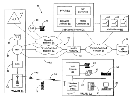
2. Exemplary Network Architecture
Figure 1 is a simplified block diagram of an exemplary wireless
telecommunications
system 10. In Figure 1, connections that carry primarily voice or other media
are shown as
solid lines and connections that carry primarily signaling are shown as dashed
lines.
Wireless telecommunications system 10 includes network elements that function
together as a wireless local area network (WLAN) 12 and network elements that
function
together as a wireless local area network (WWAN) 14. WLAN 12 may provide
wireless
coverage in a relatively limited area, such as in a building or part of a
building. In addition,
WLAN 12 may use one or more unlicensed frequency bands, such as the unlicensed
frequency
band in the 2.4 GHz range. For example, WLAN 12 may use IEEE 802.11a, IEEE
802.11b,
IEEE 802.11e, IEEE 802.11g, IEEE 802.11h, or IEEE 802.11n (wherein these and
other
members of the IEEE 802.11 family of specifications are referred to
generically herein as
"802.11x"), or variations thereof, for wireless communication. These 802.1 lx
standards are
incorporated herein by reference. Alternatively or additionally, WLAN 12 may
use IEEE
802.16, Bluetooth, HomeRF, HiperLAN, a Multichannel Multipoint Distribution
Service
(MMDS), or some other wireless protocol or format for wireless communication.
WWAN 14 may provide wireless coverage in a relatively large geographic area,
such
as an entire city, often by using a plurality of contiguous wireless coverage
areas, such as cells
CA 02608660 2007-11-16
WO 2006/127255 PCT/US2006/017737
9
or sectors. The wireless communication in WWAN 14 may occur in an analog
format, such as
the Advanced Mobile Phone Service (AMPS), or in a digital format, such as code
division
multiple access (CDMA), time division multiple access (TDMA), or Global System
for
Mobile communication (GSM), and it may occur in licensed frequency bands, such
as the 1.9
GHz PCS bands.
A multi-mode mobile station 16 has a first interface for wireless
communication with
WLAN 12 and a second interface for wireless communication with WWAN 14. Thus,
multi-
mode mobile station 16 is able to communicate with WLAN 12 when operating in
an area
served by WLAN 12 and is able to communicate with WWAN 14 when operating in an
area
served by WWAN 14. In some areas, the wireless coverage of WLAN 12 and WWAN 14
may be overlapping, and multi-mode mobile station 16 may use an arbitration
method to
determine whether to communicate with WLAN 12 or with WWAN 14.
Multi-mode mobile station 16 may be a wireless telephone, wirelessly-equipped
personal digital assistant (PDA), wirelessly-equipped laptop computer, or
other type of
wireless communication device. The first and second interfaces of multi-mode
mobile station
16 may each include an antenna, a radio frequency (RF) transceiver, and a
communication
module appropriate for communicating using the particular wireless technology.
A
communication module may be implemented by hardware, firmware, and/or
software.
WLAN 12 includes at least one wireless access point -18. Wireless access point
18
provides a wireless coverage area within which wireless access point 18 is
able to
communicate with wireless communication devices, such as multi-mode mobile
station 16,
over an air interface 20. Wireless access point 18 may be communicatively
coupled to other
network elements, e.g., via a local area network (LAN) 22. LAN 22 may carry
voice, data,
and/or other media in a packet-based format. Thus, LAN 22 may be connected to
other
communication devices that exchange voice in a packet-based format. For
example, LAN 22
CA 02608660 2007-11-16
WO 2006/127255 PCT/US2006/017737
may be connected to a voice-over-packet (VoP) telephone 24, a personal
computer 26
equipped for audio communication, e.g., equipped with a microphone and
speaker, and/or one
or more other wireless access points.
LAN 22 may also be connected to a VoP system 28 that controls VoP
communications
5 in WLAN 12. VoP system 28 may, for example, function as a private branch
exchange, such
as an "IP-PBX," and/or a media terminal adapter (MTA). VoP system 28 may, in
turn, be
communicatively coupled to a variety of wireline and/or wireless communication
devices. For
example, VoP system 28 may be connected to analog telephony devices, such as
analog
telephone 30, facsimile machines, and/or modems. VoP system 28 may also be
connected to
10 digital telephony devices, such as digital telephone 32.
LAN 22 may be communicatively coupled to a wide area packet-switched network
34,
via a network access device 36. Network access device 36 could be, for
example, a cable
modem, DSL modem, or router. Packet-switched network 34 may route packets
using a
network protocol, such as the Internet Protocol (IP), in combination with the
User Datagram
Protocol (UDP) or Transmission Control Protocol (TCP). The IP packets may be
carried over
lower level protocols, such as asynchronous transfer mode (ATM) protocols.
Protocols, such
as the Real-Time Transport Protocol (RTP), may be used to carry voice or other
media
through packet-switched network 34 in a real-time format. Relevant aspects of
RTP are
described in Schulzrinne, et al., "RTP: A Transport Protocol for Real-Time
Applications,"
Request for Comments 1889 (January 1996), which is incorporated herein by
reference.
Other protocols, such as the Session Initiation Protocol (SIP), may be used to
set up
and/or manage communication sessions through packet-switched network 34.
Voice, data,
and/or other media may be exchanged in such communication sessions. Relevant
aspects of
SIP are described in Rosenberg, et al., "SIP: Session Initiation Protocol,"
Request for
Comments 3261 (June 2002), which is incorporated herein by reference. SIP
and/or other
CA 02608660 2007-11-16
WO 2006/127255 PCT/US2006/017737
11
protocols may, in turn, use the Session Description Protocol (SDP) to describe
the
communication sessions that are being set up or managed. Relevant aspects of
SDP are
described in M. Handley, et al., "SDP: Session Description Protocol," Request
for Comments
2327 (April 1998), which is incorporated herein by reference.
In an exemplary embodiment, SIP is used to set up communication sessions
through
packet-switched network 34 that involve WLAN 12. WLAN 12 may include one or
more SIP
user agents for this SIP signaling. For example, VoP system 28 may include a
SIP user agent
to engage in SIP signaling on behalf of multi-mode mobile station 16 or other
communication
devices communicatively coupled to WLAN 12. Alternatively, multi-mode mobile
station 16
may have its own SIP user agent.
WWAN 14 may include a base transceiver station (BTS) 38 that provides a
wireless
coverage area within which BTS 38 may communicate with one or more mobile
stations, such
as multi-mode mobile station 16, over an air interface 40. Although Figure 1
shows only one
BTS, it is to be understood that WWAN 14 may include a plurality of BTSs that
may provide
a plurality of wireless coverage areas. The communications between BTS 38 and
multi-mode
mobile station 16 may occur in a digital format, such as CDMA, TDMA, GSM, or
they may
occur in an analog format, such as AMPS. The communications could be voice
only, data
only (e.g., using EV-DO), or may include a combination of voice and data
(e.g., using EV-
DV). A preferred wireless communications format is cdma2000 such as described
in
EIA/TIA/IS-2000 Series, Rev. A (published March 2000), which is incorporated
herein by
reference.
BTS 38 may be controlled by a base station controller (BSC) 42, which, in
turn, may
be controlled by a mobile switching center (MSC) 44. Although Figure 1 shows
only one
MSC and only one BSC, it is to be understood that WWAN 14 may include a
plurality of
MSCs, which may, in turn, control a plurality of BTSs, via a plurality of
BSCs. MSC 44 also
CA 02608660 2007-11-16
WO 2006/127255 PCT/US2006/017737
12
has access to a visitor location register (VLR) 46. VLR 46 stores data records
for mobile
stations, such as multi-mode mobile station 16, that are being served by MSC
44. A data
record stored in VLR 46 for a mobile station may identify the mobile station,
e.g., by mobile
directory number (MDN), mobile station identification (MSID), and/or
electronic serial
number (ESN). The data record may also include status information for the
mobile station,
such as whether the mobile station is busy, and may also include a service
profile that
identifies the services to which the mobile station subscribes. The data
record may also
include other information relating to the mobile station. Although Figure 1
shows VLR 46 as
a network element separate from MSC 44, VLR 46 may be integrated or co-located
with MSC
44.
WWAN 14 may also include a home location register (HLR) 48 that stores a data
record for multi-mode mobile station 16. The data record stored in HLR 48 for
multi-mode
mobile station 16 may identify multi-mode mobile station 16, such as by MDN,
MSID, and/or
ESN and may include a last known location of multi-mode mobile station 16. For
example,
the data record may identify the VLR that most recently registered multi-mode
mobile station
16 with HLR 48. The data record may also include status information for multi-
mode mobile
station 16, a service profile for multi-mode mobile station 16, and other
information relating to
multi-mode mobile station 16.
MSC 44 is connected to the public switched telephone network (PSTN) 50. PSTN
50
may use an out-of-band signaling system, such as Signaling System 7 (SS7) to
route calls.
Thus, PSTN 50 may include a circuit-switched network 52 that carries bearer
traffic, i.e., the
voice or other media in calls, and a signaling network 54 that carries
signaling traffic used to
set up, tear down, monitor, and control calls. Circuit-switched network 52 may
include a
plurality of trunks, with each trunk carrying media in a time division
multiplex (TDM) format.
Signaling system 54 may include a plurality of networked signal transfer
points (STPs).
CA 02608660 2007-11-16
WO 2006/127255 PCT/US2006/017737
13
PSTN 50 may also be connected to various landline telephony endpoints,
exemplified
in Figure 1 by landline telephone 56. More particularly, landline telephone 56
may be
connected to a switching system, such as service switching point (SSP) 58,
which, in turn, may
have a bearer connection to circuit-switched network 52 and a signaling
connection to
signaling network 54.
MSC 44 may communicate with signaling network 54, e.g., using SS7, to route
calls
via circuit-switched network 52 to and from mobile stations being served by
WWAN 14, such
as multi-mode mobile station 16. To provide telecommunications services to
mobile stations
being served by WWAN 14, such as multi-mode mobile station 16, MSC 44 may also
communicate with HLR 48 via signaling network 54. The communications between
MSC 44
and HLR 48 may conform to IS-41 specifications. A recent revision of the IS-41
specifications, ANSI/TIAIEIA-41-D-97, published in December 1997, is
incorporated herein
by reference. The IS-41 signaling may be carried in signaling network 54 as an
SS7
application layer.
Packet-switched network 34 may be communicatively coupled to circuit-switched
network 52, via a media gateway 60. Media gateway 60 may convert between media
formats
used in circuit-switched network 52 and packet-switched network 34. For
example, media
gateway 60 may receive media from circuit-switched network 52 in a TDM format
and
convert the media into an RTP format for transmission over packet-switched
network 34, and
vice-versa. Media gateway 60 may also be connected to, or integrated with,
MSCs, such as
MSC 44. Thus, MSC 44 may have a bearer connection with media gateway 60 via an
intermachine trunk 62.
A media serer 64 may also be communicatively coupled to packet-switched
network
34. Media server 64 provides a plurality of conference bridges, such as
conference bridges 66,
68, and 70, each of which may be able to bridge three or more call legs that
extend through
CA 02608660 2007-11-16
WO 2006/127255 PCT/US2006/017737
14
packet-switched network 34 as three or more media streams (e.g., in an RTP
format). For
example, with multi-mode mobile station 16 involved in a call with an
endpoint, conference
bridge 66 might bridge together: (i) a first call leg that extends from media
server 64 to multi-
mode mobile station 16 via packet-switched network 34, WLAN 12, and air
interface 20; (ii) a
second call leg that extends from media server 64 to multi-mode mobile station
16 via packet-
switched network 34, media gateway 60, circuit-switched network 52, WWAN 14,
and air
interface 40; and (iii) a third call leg that extends from the endpoint, e.g.,
landline telephone
56, to media server 64 via SSP 58, circuit-switched network 52, media gateway
60, and
packet-switched network 34.
Although Figure 1 shows three conferences bridges in media server 64, it is to
be
understood that media server 64 could include a greater or fewer number of
conference
bridges. In addition, conference bridges 66, 68, and 70 could be provided by
one or more
other network elements. For example, conference bridges 66, 68, and 70 could
be provided by
a media resource function (MRF) or by a media gateway.
Each conference bridge in media server 64 may be associated with a particular
multi-
mode mobile station. More particularly, each conference bridge may be given a
conference
bridge identifier that is, in turn, assigned to a particular multi-mode mobile
station. For
example, conference bridge 66 might be associated with multi-mode mobile
station 16. As
described in more detail, this association may result in -having all calls to
or from multi-mode
mobile 16 station routed through conference bridge 66.
Wireless telecommunications system 10 may include a conference bridge
identifier
(CBI) database 72 that keeps track of which conference bridges are assigned to
which multi-
mode mobile stations. For example, CBI database 72 may store conference bridge
identifiers
of the conference bridges provided by media server 64 and may store mobile
station identifiers
of multi-mode mobile stations so that the mobile station identifiers are
mapped to the
CA 02608660 2007-11-16
WO 2006/127255 PCT/US2006/017737
conference bridge identifiers of their associated conference bridges. Such
mobile station
identifiers may include, for example, MDN, MSID, and/or ESN. In this way, a
mobile station
identifier of a multi-mode mobile station may be used to query CBI database 72
and obtain the
conference bridge identifier of the conference bridge associated with that
multi-mode mobile
5 station.
CBI database 72 may be communicatively coupled to packet-switched network 34,
as
shown in Figure 1. Alternatively, CBI database 72 could be provided in
telecommunications
system 10 in other ways. For example, CBI database 72 could be integrated into
a network
element such as a home subscriber server (HSS).
10 Media server 64 could be controlled by a call control system 74 that
functions to route
calls to and from multi-mode mobile stations through their associated
conference bridges in
media server 64, for example, via packet-switched network 34, PSTN 50, and
media gateway
60. Call control system 74 may include a number of functional components, such
as a media
controller 76, a SIP server 78, a signaling gateway 80, and an IP VLR 82.
These components
15 may be provided in a single network element, such as softswitch or a call
session control
function (CSCF). Alternatively, these components may be distributed among
multiple
network elements.
Media controller 76 may function to control media gateway 60, for example, to
extend
calls from PSTN 50 to packet-switched network 34, or vice-versa, and may
function-to control
media server 64 to set up specific conference bridges for calls to and from
their associated
multi-mode mobile stations. Media controller 76 may communicate with media
gateway 60
and media server 64 via signaling links, e.g., using the Media Gateway Control
Protocol
(MGCP), H.248/Megaco, SIP, VoiceXML, and/or other protocols.
SIP server 78 may communicate with SIP user agents (which may be included in
multi-mode mobile stations or in other network elements, such as VoP system
28, that act on
CA 02608660 2007-11-16
WO 2006/127255 PCT/US2006/017737
16
behalf of multi-mode mobile station) to set up and control voice calls and
other
communication sessions through packet-switched network 34. For example, SIP
server 78
may function as a SIP registrar that registers SIP user agents through the use
of the SIP
REGISTER method. SIP server 78 may also function as a SIP proxy server, e.g.,
to set up
communication sessions using the SIP INVITE method.
Signaling gateway 80 functions to convert between the signaling format used in
packet-switched network 34, e.g., SIP, and the signaling format used in
signaling network 54,
e.g., SS7 and IS-41. Thus, using signaling gateway 80, call control system 74
can route calls
that originate from PSTN 50 through packet-switched network 34 and can route
calls that
originate from packet-switched network 34 through PSTN 50.
IP VLR 82 serves as a visitor location register for packet-switched network
34, storing
a data record for each multi-mode mobile station that has registered via
packet-switched
network 34. More particularly, when a multi-mode mobile station associates
with WLAN 12,
the multi-mode mobile station may register for services via packet-switched
network 34, e.g.,
by sending a SIP REGISTER message to SIP server 78. In response, call control
system 74
may obtain a data record for that multi-mode mobile station from HLR 48, e.g.,
by having
signaling gateway 80 send an IS-41 REGNOT message to HLR 48, and then store
that data
record in IP VLR 82. In this way, IP VLR 82 keeps track of which multi-mobile
stations are
currently being served by WLAN 12.
3. Exemplary Operation
Figures 2-6 are flow charts illustrating exemplary methods of operation. More
particularly, Figure 2 illustrates an exemplary method of establishing a call
from an endpoint
to a multi-mode mobile station via a WWAN, using the conference bridge
associated with the
multi-mode mobile station. Figure 3 illustrates an exemplary method of
effecting a handoff of
the WWAN call established as in Figure 2 so that the call continues over a
WLAN. Figure 4
CA 02608660 2007-11-16
WO 2006/127255 PCT/US2006/017737
17
illustrates an exemplary method of establishing a call originated by the multi-
mode mobile
station via a WLAN, using the conference bridge associated with the multi-mode
mobile
station. Figure 5 illustrates an exemplary method of effecting a handoff of
the WLAN call
established as in Figure 4 so that the call continues over the WWAN. Figure 6
illustrates an
exemplary method of using the conference bridge to re-connect the multi-mode
mobile station
when its call leg has been unintentionally dropped. The examples of Figures 2-
6 assume the
network architecture of Figure 1. However, it is to be understood that other
network
architectures could be used.
With reference to Figure 2, an exemplary process may begin when a caller dials
a
directory number associated with a multi-mode mobile station (e.g., its MDN),
as indicated by
block 100. For purposes of illustration, it will be assumed that the caller is
calling from a
landline station, e.g., landline telephone 56 in Figure 1. However, it is to
be understood that
the caller could also be calling from a mobile station (via either a WWAN or a
WLAN), from
a wireline station coupled to a packet-switched network, or from some other
endpoint.
A call control system then receives a request to establish the call to the
multi-mode
mobile station, as indicated by block 102. The request may take the form of
call set-up
signaling, such as SS7 signaling for calls from PSTN 50 or SIP signaling for
calls from
packet-switched network 34. Thus, if landline telephone 56 is originating the
call, SSP 58
may generate an SS7 IAM message that identifies the multi-mode mobile station,
e.g., by its
MDN, as the called party. Signaling gateway 80 in call control system 74 may
then receive
the SS7 TAM message via signaling network 54.
In response to this request, the call control system queries a CBI database to
identify
which conference bridge is associated with the called multi-mode mobile
station, as indicated
by block 104. For example, call control system 74 may send a query to CBI
database 72 that
identifies the called multi-mode mobile station, e.g., by its MDN. CBI
database 72 may then
CA 02608660 2007-11-16
WO 2006/127255 PCT/US2006/017737
18
perform a look-up and respond with a conference bridge identifier that
identifies the
conference bridge that has been assigned to the multi-mode mobile station.
The call control system then routes the call to the identified conference
bridge, as
indicated by block 106. For example, if conference bridge 66 is to be used for
the call, media
controller 76 of call control system 74 may signal to media server 64 to
prepare conference
bridge 66 for the call. In this signaling, media controller 76 may specify
that conference
bridge 66 is to be used by providing the conference bridge identifier obtained
from CBI
database 72.
The call control system may also determine where the called multi-mode mobile
station is currently operating, as indicated by block 108. For example, call
control system 74
may determine whether the called multi-mode mobile station is currently being
served by
WLAN 12 or by WWAN 14. To do this, signaling gateway 80 may send an IS-41
LOCREQ
message to HLR 48.
In this example, the called multi-mode mobile station is being served by WWAN
14.
Thus, in response to the IS-41 LOCREQ message, HLR 48 checks its data record
for the
called multi-mode mobile station and thereby determines that the called multi-
mode mobile
station is currently being served by MSC 44. HLR 48 then sends an IS-41
ROUTEREQ
message to MSC 44 to obtain a temporary local directory number (TLDN) and
forwards this
TLDN to signaling gateway 80 in response to the LOCREQ message.
Once the called multi-mode mobile station is located, the call control system
extends
the call from the conference bridge to the called multi-mode mobile station,
via the WWAN,
as indicated by block 110. For example, media controller 76 may signal to
media gateway 60
and media server 64 to set up a voice session through packet-switched network
34, and
signaling gateway 80 may use the TLDN from the LOCREQ response to route the
call through
signaling network 54 (e.g., in an SS7 LAM message) from media gateway 60 to
MSC 44.
CA 02608660 2007-11-16
WO 2006/127255 PCT/US2006/017737
19
The WWAN receives the signaling to terminate the call to the multi-mode mobile
station and, in response, notifies the multi-mode mobile station of the
incoming call (i.e.,
pages and alerts the multi-mode mobile station). The multi-mode mobile station
may then
answer the call, as indicated by block 112. In this way, a WWAN call leg is
established
between the conference bridge and the called multi-mode mobile station, as
indicated by block
114, through which the multi-mode mobile station and endpoint can exchange
voice or other
media via the WWAN. Thus, landline telephone 56 and conference bridge 66 can
exchange
media via SSP 58, circuit-switched network 52, media gateway 60, and packet-
switched
network 34, and conference bridge 66 and multi-mode mobile station 16 can
exchange media
via packet-switched network 34, media gateway 60, circuit-switched network 52
(or IMT 62),
WWAN 14, and air interface 40.
Figure 3 illustrates an exemplary process for effecting a handoff from the
WWAN to
the WLAN. At some point during the call, the multi-mode mobile station may
determine that
a different wireless network (e.g., WLAN 12) is available and preferred, as
indicated by block
116. The multi-mode mobile station may use any of various methods to determine
when to
check for availability of the other wireless network. In some cases, the multi-
mode mobile
station may periodically check for availability, or it may do so at the
instance of the user.
Alternatively, a triggering event may cause the multi-mode mobile station to
determine that it
should check for availability of the second wireless network. For example, the
multi-mode
mobile station may use information about its location or movement ' to
determine when to
check for availability of the second wireless network. Examples of such
approaches are
described in U.S. Patent Application No. 10/391,158, filed March 18, 2003,
titled "Method for
Determining Availability of a Radio Network," in U.S. Patent Application No.
10/629,406,
filed July 29, 2003, titled "Method for Determining Availability of a Radio
Network," and in
U.S. Patent Application No. 10/980,727, titled "Method and System for
Triggering Events in a
CA 02608660 2007-11-16
WO 2006/127255 PCT/US2006/017737
Wireless Network," filed November 3, 2004, which applications are incorporated
herein by
reference.
Once the multi-mode mobile station determines that the other wireless network
is
available, the multi-mode mobile station may then determine whether it is
preferred. The
5 determination that the other wireless network is preferred could be based on
pre-set
preferences and/or could depend on various criteria, such as the quality of
the link and/or the
availability of desired services (e.g., voice service) using the other
wireless network.
In response to the determination that the WLAN is available and preferred, the
multi-
mode mobile station registers with the WLAN, as indicated by block 118. For
example, the
10 multi-mode mobile station may transmit a SIP REGISTER message to SIP server
78. The
multi-mode mobile station then calls a predetermined handoff number using its
WLAN
interface, as indicated by block 120. If the multi-mode mobile station
includes a SIP user
agent, the multi-mode mobile station may do this by sending SIP server 78 a
SIP INVITE
message with a Request-URI that includes the handoff number. If the multi-mode
mobile
15 station does not include a SIP user agent, the multi-mode mobile station
may use a different
protocol to send a message to a network element that does include a SIP user
agent (e.g., VoP
system 28), which then sends a SIP INVITE message on behalf of the multi-mode
mobile
station.
The call control system recognizes from the handoff number specified in the
SIP
20 INVITE message that the caller is a multi-mode mobile station, with an
associated conference
bridge, that is requesting a handoff. The call control system then queries the
CBI database to
identify which conference bridge is associated with the multi-mode mobile
station, as
indicated by block 122. For example, call control system 74 may send CBI
database 72 a
query that includes an identifier of the multi-mode mobile station (e.g., an
MDN, MSID, or
ESN) obtained from the SIP INVITE message. CBI database 72 may then respond
with a
CA 02608660 2007-11-16
WO 2006/127255 PCT/US2006/017737
21
conference bridge identifier that identifies the multi-mode mobile station's
designated
conference bridge, e.g., conference bridge 66.
The call control system then sets up a voice session between the identified
conference
bridge and the multi-mode mobile station via the WLAN, as indicated by block
124. To do
this, media controller 76 may communicate with media server 64 to prepare
conference bridge
66 for the voice session, and SIP server 78 may respond to the SIP INVITE
message with a
200 OK message. In this way, a WLAN call leg is established between the multi-
mode mobile
station and its associated conference bridge, as indicated by block 126,
through which the
multi-mode mobile station and the endpoint can exchange voice and/or other
media. Thus,
landline telephone 56 and conference bridge 66 can exchange media via SSP 58,
circuit-
switched network 52, media gateway 60, and packet-switched network 34, and
conference
bridge 66 and multi-mode mobile station 16 can exchange media via packet-
switched network
34, WLAN 12, and air interface 20.
Moreover, the conference bridge bridges the WWAN and WLAN call legs, as
indicated by block 128. In particular, the conference bridge mixes the voice
or other media for
the WWAN and WLAN call legs, so that media transmitted by the endpoint is sent
to the
multi-mode mobile station via both the WWAN and the WLAN call legs, and media
that the
multi-mode mobile station transmits over either call leg is sent to the
endpoint.
At some point, for example, when the multi-mode mobile station starts
receiving media
via its WLAN interface, the multi-mode mobile station drops the WWAN call leg,
e.g., by
transmitting a release message, as indicated by block 130. In this way, the
conference bridge
can beneficially facilitate a soft handoff between the WWAN and the WLAN.
Calls originating from multi-mode mobile stations may also be routed through
their
respective conference bridges, as illustrated in Figures 4 and 5. For purposes
of illustration,
the multi-mode mobile station is currently being served by a WLAN, e.g., WLAN
12, in the
CA 02608660 2007-11-16
WO 2006/127255 PCT/US2006/017737
22
example of Figures 4 and 5. With reference to Figure 4, the process may begin
when the user
of a multi-mode mobile station dials the directory number of an endpoint,
e.g., landline
telephone 56, as indicated by block 200.
In response, the multi-mode mobile station transmits a request, via its WLAN
interface, to establish a call to the endpoint, as indicated by block 202. For
example, the
multi-mode mobile station may transmit (or another network element may
transmit on behalf
of the multi-mode mobile station) a SIP INVITE message to SIP server 78. The
SIP INVITE
message may include a Request-URI that identifies the endpoint and may
identify the calling
multi-mode mobile station, e.g., by MDN, MSID, or ESN.
A call control system receives the request and recognizes (e.g., from an
identification
of the multi-mode mobile station contained in the request) that the call
should be routed
through the conference bridge that is associated with the multi-mode mobile
station, as
indicated by block 204. To identify which conference bridge is associated with
the multi-
mode mobile station, the call control system queries a CBI database, as
indicated by block
206. For example, call control system 74 may send CBI database 72 a query that
identifies the
calling multi-mode mobile station, and CBI database 72 may respond with a
conference bridge
identifier that specifies what conference bridge to use for the call, e.g.,
conference bridge 66.
The call control system then establishes a call leg between the endpoint and
the
identified conference bridge, as indicated- by block 208. For example, media
controller 76
may signal to media server 64 to prepare conference bridge 66 for the call,
and signaling
gateway 80 may transmit an SS7 IAM message through signaling network 54 to
route the call
to the called endpoint, e.g., landline telephone 56.
Once the called endpoint answers, the call leg between the called endpoint and
the
conference bridge is completed. The call control system then accepts the multi-
mode mobile
station's request to establish a call to the endpoint, as indicated by block
210. For example,
CA 02608660 2007-11-16
WO 2006/127255 PCT/US2006/017737
23
the call control system may send a SIP 200 OK message to the multi-mode mobile
station,
which may then respond with an ACK acknowledgement. In this way, a WLAN call
leg is
established between the conference bridge and the multi-mode mobile station,
as indicated by
block 212, through with the multi-mode mobile station and the called endpoint
can exchange
voice or other media. Thus, once the call to landline telephone 56 is
established, landline
telephone 56 and conference bridge 66 can exchange media via SSP 58, circuit-
switched
network 52, media gateway 60, and packet-switched network 34, and conference
bridge 66
and multi-mode mobile station 16 can exchange media via packet-switched
network 34,
WLAN 12, and air interface 20.
Figure 5 illustrates an exemplary process for effecting a handoff from the
WLAN to
the WWAN. At some point during the call, the multi-mode mobile station
determines that the
WWAN is available and preferred, as indicated by block 214. In response, the
multi-mode
mobile station registers with the WWAN, as indicated by block 216. For
example, if the
multi-mode mobile station is an area served by MSC 44, then the multi-mode
mobile station
may transmit a registration message and MSC 44 may responsively send an IS-41
REGNOT
message to HLR 48. The multi-mode mobile station then calls a predetermined
handoff
number using its WWAN interface, as indicated by block 218. The signaling for
the call to the
handoff number is routed to the call control system, as indicated by block
220. For example,
MSC 44 may generate an SS7 IAM message that identifies the handoff number as
the called
number. Signaling network 54 may then route the SS7 IAM message to signaling
gateway 80,
e.g., based on a point code for signaling gateway 80 that is associated with
the handoff
number.
The call control system receives this signaling and recognizes (e.g., from an
identification of the multi-mode mobile station) that the call should be
routed through the
multi-mode mobile station's conference bridge. To identify which conference
bridge is
CA 02608660 2007-11-16
WO 2006/127255 PCT/US2006/017737
24
associated with the multi-mode mobile station, the call control system queries
the CBI
database, as indicated by block 222. The call control system then routes the
call to the
identified conference bridge, as indicated by block 224.
In this way, a WWAN call leg is established between the multi-mode mobile
station
and the conference bridge, as indicated by block 226, through which the multi-
mode mobile
station and the called endpoint can exchange voice or other media. Moreover,
the conference
bridge bridges the WWAN and WLAN call legs, as indicated by block 228. As a
result, the
multi-mode mobile station can receive media from the endpoint via either call
leg and can
transmit media to the endpoint via either call leg.
At some point, for example, when the multi-mode mobile station starts
receiving media
via its WWAN interface, the multi-mode mobile station drops the WLAN call leg,
as indicated
by block 230, e.g., by de-registering with SIP server 78. To de-register,
multi-mode mobile
station 16 may, for example, transmit a SIP REGISTER message with an
expiration period of
0. The multi-mode mobile station may do this, for example, when it begins to
receive media
via its WWAN interface. Alternatively, the multi-mode mobile station may
transmit a SIP
BYE message.
Once the WLAN call leg is dropped, the multi-mode mobile station continues
using the
WWAN call leg for the call. In this way, a soft handoff from the WLAN to the
WWAN may
be effected.
The approach of routing calls to and from a multi-mode mobile station through
its
associated conference bridge can also facilitate the process of re-connecting
the multi-mode
mobile station when its call leg has been unintentionally dropped, as
illustrated in Figure 6.
The process may begin when the multi-mode mobile station is engaged in a call
with an
endpoint via a conference bridge in a media server, as indicated by block 300.
Thus, the call
includes an endpoint call leg that extends between the endpoint and the
conference bridge and
CA 02608660 2007-11-16
WO 2006/127255 PCT/US2006/017737
a multi-mode mobile station call leg that extends between the multi-mode
mobile station and
the conference bridge. The call may have been originated by either the multi-
mode mobile
station or the endpoint. In addition, the multi-mode mobile station may be
involved in the call
via either the WWAN or the WLAN. Thus, the call could have been established as
set forth in
5 Figure 2 or Figure 4.
At some point during the call, the multi-mode mobile station's call leg is
unintentionally dropped, as indicated by block 302. This may occur, for
example, because of a
temporary degradation in signal quality or for some other reason. The media
server may
detect the dropped call leg and, in response, may play an announcement to the
endpoint, as
10 indicated by block 304. The announcement could be, for example, a pre-
recorded or speech-
synthesized message asking the party at the endpoint to please hold because
the other party has
been dropped from the call and is attempting to re-connect. The announcement
may be chosen
so as to fill up the expected amount of time needed for the multi-mode mobile
station to re-
connect. In this regard, the media server may allow the multi-mode mobile
station a
15 predetermined period of time, e.g., 15 seconds, within which to re-connect
before releasing the
endpoint's call leg.
The multi-mode mobile station also detects the dropped call leg and, in
response, calls
a predetermined re-establishment number, as indicated by block 306. The re-
establishment
number could be, for example, the same directory number as the handoff number.
The multi-
20 mode mobile station could transmit the call re-establishment request via
the same wireless
network as the dropped call leg. Alternatively, if the other wireless network
is available, then
the multi-mode mobile station may register with the other wireless network and
then transmit
the call re-establishment request.
The signaling for the call to the re-establishment number is routed to the
call control
25 system, as indicated by block 308. The call control system then queries the
CBI database to
CA 02608660 2007-11-16
WO 2006/127255 PCT/US2006/017737
26
identify the multi-mode mobile station's conference bridge, as indicated by
block 310. For
example, call control system 74 may send CBI database 72 a query that includes
an identifier
of the multi-mode mobile station (e.g., an MDN, MSID, or ESN) that the multi-
mode mobile
station included in its call re-establishment request. CBI database 72 may
respond with a
conference bridge identifier that identifies the multi-mode mobile station's
designated
conference bridge, i.e., the conference bridge being used for the call. The
call control system
then routes the re-establishment call to the identified conference bridge, as
indicated by block
312. In this way, the multi-mode mobile station's call leg is re-established,
as indicated by
block 314.
4. Conclusion
Exemplary embodiments of the present invention have been described above.
Those
skilled in the art will understand, however, that changes and modifications
may be made to these
embodiments without departing from the true scope and spirit of the invention,
which is defined
by the claims.