Note: Descriptions are shown in the official language in which they were submitted.
CA 02608748 2007-11-19
WO 2006/124380 PCT/US2006/017794
TRAINING ENHANCED PSEUDO ACCOMMODATION METHODS,
SYSTEMS AND DEVICES FOR MITIGATION OF PRESBYOPIA
BACKGROUND OF THE INVENTION
[0001] This invention generally relates to optical correction, and in
particular provides
methods, devices, and systems for mitigating or treating presbyopia and/or
other vision
conditions. Exemplary embodiments employ aspherical refractive corrections for
providing
appropriate accommodative power with changes in pupil size.
[0002] Presbyopia is a condition that affects the accommodation properties of
the eye. As
objects move closer to a young, properly functioning eye, the effects of
ciliary muscle
contraction increases the optical power of the lens of the eye to focus at
nearer distances.
Hence, accommodation can allow the eye to focus and refocus between near and
far objects.
[0003] Presbyopia normally develops as a person ages, and is associated with a
natural
progressive loss of accommodation, sometimes referred to as "old sight." The
presbyopic eye
often loses the ability to rapidly and easily refocus on objects at varying
distances. Although
the condition progresses over the lifetime of an individual, the effects of
presbyopia usually
become noticeable after the age of 45 years. By the age of 65 years, the
crystalline lens has
often lost most of its elastic properties and has only limited ability to
change shape. Residual
accommodation refers to the amount of accommodation that remains in the eye. A
lower
degree of residual accommodation contributes to more severe presbyopia,
whereas a higher
amount of residual accommodation correlates with less severe presbyopia.
[0004] A variety of methods and devices for treatment of presbyopia have been
employed,
with varying results. The goal of such treatments is generally to allow the
eye to see clearly
both distant objects and near objects. Reading glasses have traditionally
allowed the eye to
focus on and maintain a clear image of near objects by adding plus power
diopter to the eye,
using an approach similar to that applied for treatment of farsightedness or
hyperopia. To
facilitate viewing both near and far objects, presbyopia has also been treated
with bifocal
eyeglasses. A variety of other approaches have also been suggested, but none
of the known
presbyopia-treatment modalities that are commonly used by patients have been
shown to be
without drawbacks for at least some cases.
1
CA 02608748 2011-05-06
[0005] In work associated with embodiments of the present invention, it has
recently been proposed
to provide refractive shapes which take of advantage of changes in a size of a
patient's pupil with
changes in viewing distances, so as to provide enhanced optical imaging. U.S.
Patent No.
7,293,873, entitled "Presbyopia Correction Using Patient Data," presents a
variety of approaches for
establishing prescriptions that mitigate or treat presbyopia of particular
patients. Suitable shapes
may be optically optimized, scaled or otherwise varied, and/or may provide
optical powers that
change with pupil size, with the preferred prescriptions often being tailored
to measurements of a
patient's eye at differing viewing conditions. U.S. Patent No. 7,387,387,
entitled "Correction of
Presbyopia Using Adaptive Optics and Associated Methods," describes systems
and devices which
may be suited for accurately measuring characteristics of the eye at differing
viewing distances. By
taking advantage of these recent improvements, many patients may experience
enhanced abilities to
view at different viewing distances without the inconvenience of reading
glasses, bifocals, or the
like.
[00061 While the recent proposals may represent a significant advancement in
the art, as with many
such successes, still further improvements would be desirable. In particular,
work in connection
with embodiments of the present invention indicates that the benefits of
pseudo accommodation can
be limited in at least some cases. Hence, it would be advantageous to provide
improved devices,
systems, and methods for treatment of presbyopia, and particularly to provide
such improvements
so as to extend the benefits of the recently proposed presbyopia mitigation
techniques to additional
individual patients, groups of patients, and the like. It may also be
advantageous to increase the
clinical efficacy of presbyopia-mitigating techniques so as to improve optical
imaging, acuity,
and/or patient satisfaction.
BRIEF SUMMARY OF THE INVENTION
[0007] Embodiments of the present invention generally provide improved
devices, systems, and
methods for developing prescriptions for and/or treating one or both eyes of a
patient. Embodiments
of the invention are particularly well suited for addressing presbyopia, and
may help provide
improved viewing at differing viewing distances using an alteration to the
refractive tissues of the
eye, together with changes in the response of the patient's visual system. The
visual system response
may include, for example, using residual accommodation in a manner similar to
that employed by a
latent hyperope. A variety of other helpful visual system responses may also
be taken advantage of,
including a trained response of the pupil, trained psychophysics, or the like.
Advantageously, the
2
CA 02608748 2011-05-06
refractive prescription may be tailored to take advantage of one or more of
these visual system
imaging stimuli responses. Although full visual response training time may be
surprisingly long, so
that if training is not started until after a procedure the patient's
satisfaction may not peak until
significantly after the refractive properties of the eye have stabilized, once
a patient's visual
response has adapted to a suitable refractive prescription the patient may
achieve accuity results of
20/20 vision or better and J3 or better. Refractive prescriptions (along with
devices and methods for
their generation and/or imposition) are also provided which are particularly
well suited to take
advantage of the subsequent visual system response so as to mitigate
presbyopia for a wide range of
patients.
[0008] A first embodiment provides a method for treating presbyopia in a
vision system of the
patient. The vision system includes an eye, and the method comprises applying
a refractive
prescriptive change to the eye. The refractive change alters optical
properties of the eye so as to
provide a first near acuity and a first far acuity. In response to the altered
optical properties of the
eye, a modified response of the visual system is induced so as to provide a
second near acuity which
is better than the first near acuity, and/or a second far acuity which is
better than the first far acuity,
such that presbyopia of the eye is mitigated.
[0009] The modified response of the visual system may significantly improve
visual acuity from an
optically stabilized acuity to a trained acuity. This improvement may occur
significantly after the
altered optical properties of the eye have substantially stabilized. For
example, when the optical
properties of the eye are applied using a LASIK procedure, the eye may have
substantially
stabilized optically in as little as one hour after the procedure.
Nonetheless, a significant
improvement in near visual acuity may be provided only after more than one
hour later than the
LASIK procedure, in many cases occurring more than one day after the LASIK
procedure, and
often occurring more than one week after the LASIK procedure. In some cases,
the full benefit of a
presbyopia treatment may be provided more than one month after the LASIK
procedure, that a
patient measured one month after the LASIK procedure can have a first visual
acuity when viewing
at a near distance, and that same patient may have a significantly improved
second near visual
acuity when measured still later, such as three months after the LASIK
procedure.
[0010] A modified response of the visual system will often include a modified
tissue response to
imaging stimuli. This tissue response may comprise psychophysics, a trained
pupil
3
CA 02608748 2011-05-06
pseudo-accommodation, latent presbyopia-like accommodation, and/or the like.
Such visual system
responses may be obtained by training the visual system of the patient to take
advantage of the
altered optical characteristics available after the refractive prescription is
applied to the eye.
Advantageously, the visual system response may be anticipated, and the
refractive prescription may
be generated using the anticipated visual system response. The anticipated
visual system response
may be determined by studying the visual system responses of prior patients,
and/or may be
determined by measurements of the patient being treated. For example, when a
permanent refractive
alteration of the patient's eye is planned, temporary refractive alterations
(such as contact lenses or
the like) may be used in such measurements.
[0011] Ideally, the initial far acuity will be at least 20/20, so that the
mitigation of presbyopia may
be effected by improving near visual acuity after the prescriptive change is
imposed. The refractive
prescription will often be tailored or determined using a measured response of
the eyes of the
patient, often by measuring a pupil dilation response, a residual
accommodation, or the like. The
anticipated visual system response may correspond to a rate of change in total
overall effective
power of the eye with changes in pupil size, allowing a refractive
prescription to be used even
though an effective refractive power of the prescription has a rate of change
that is lower than the
total rate. For example, the refractive prescription may correspond to a
change in effective power
with changes in pupil size at a rate of between about 0.4 D per millimeter and
about 0.6 D per
millimeter. After the refractive prescription is imposed, the a change in
manifest power with a
change in pupil size (which may correspond to the total compensation rate) may
be significantly
greater than this rate.
[0012] Another embodiment provides a system for treating presbyopia in a
visual system of a
patient. The visual system includes an eye, and the system comprises a laser
for resculpting the eye
of the patient according to a refractive prescription. The prescription alters
optical properties of the
eye so that the eye, after optical stabilization, has a first near acuity and
first far acuity. A processor
is coupled to the laser resculpting system. The processor determines the
refractive prescription from
optical properties of the eye, such that the optical properties of the eye as
altered by the prescription
induce a modified response of the visual system. This modified response
provides a second near
acuity better than the first near acuity, or a second far acuity better than
the first far acuity. Hence,
presbyopia of the eye is mitigated.
[0013] Yet another embodiment provides a system for determining a refractive
prescription so as to
mitigate presbyopia in a visual system of a patient. The visual system
includes an eye with
4
CA 02608748 2011-05-06
refractive tissue. The system includes an aberrometer for measuring initial
optical properties of the
eye, and a processor coupled to the aberrometer. The processor determines the
refractive
prescription from the initial optical properties of the eye so that the
refractive tissues of the eye
provide a first near acuity and first far acuity. The altered optical
properties of the eye are
configured by the processor to induce a modified response of the visual system
so as to provide a
second near acuity better than the first near acuity, or a second far acuity
better than the first far
acuity (and in some cases both). Hence, the presbyopia of the eye will be
mitigated.
[0013a] Another embodiment provides a system for treating presbyopia in a
visual system of a
patient, the visual system including an eye. The system includes a laser for
resculpting the eye of
the patient according to a refractive prescription, the prescription altering
optical properties of the
eye so that the eye, after optical stabilization has a first near acuity and a
first far acuity. The
system further includes a processor coupled to the laser resculpting system,
and a machine-readable
medium storing instructions for directing the processor to determine the
refractive prescription from
optical properties of the eye, such that the altered optical properties of the
eye induce a modified
response of the visual system so as to provide a second near acuity better
than the first near acuity,
or a second far acuity better than the first far acuity, such that presbyopia
of the eye is mitigated.
[0013b] Another embodiment provides a system for determining a refractive
prescription so as to
mitigate presbyopia in a visual system of a patient, the visual system
including an eye with
refractive tissues. The system includes an aberrometer for measuring initial
optical properties of the
eye, and a processor coupled to the aberrometer. The system further includes a
machine-readable
medium storing instructions for directing the processor to determine the
refractive prescription from
the initial optical properties of the eye so that the refractive tissues of
the eye provide, when the eye
has optically stabilized, a first near acuity and a first far acuity. The
altered optical properties of the
eye are configured to induce a modified response of the visual system so as to
provide a second near
acuity better than the first near acuity, or a second far acuity better than
the first far acuity, such that
presbyopia of the eye is mitigated.
[0013c] Other aspects and features of illustrative embodiments will become
apparent to those
ordinarily skilled in the art upon review of the following description of such
embodiments in
conjunction with the accompanying figures.
5
CA 02608748 2011-05-06
BRIEF DESCRIPTION OF THE DRAWINGS
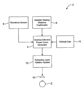
[0014] Fig. 1 is a schematic block diagram illustrating a system for
generating and imposing a
refractive prescription suitable for inducing a response of the visual system
so as to mitigate
presbyopia.
[0015] Fig. 2 illustrates a laser eye surgery system for imposing a refractive
prescription on a cornea
of a patient.
[0016] Fig. 2 A is a schematic illustration showing a block diagram of a
computer of the systems of
Figs. 1 and/or 2.
[0017] Fig. 3 is a schematic illustration showing a wavefront sensor system
for measuring refractive
aberrations of the eye, for use in the system of Fig. 1.
[0018] Fig. 4 is a schematic diagram of a system for measuring a response to
varying viewing
distances for use in the system of Fig. 1.
[0019] Figs. 5 and 6 are a side view and a perspective view, respectively, of
a basic refractive shape
which can be scaled or modified to provide a desired effective power profile
and/or to induce a
desirable visual system response so as to mitigate presbyopia using the system
of Fig. 1.
[0020] Fig. 7 graphically illustrates changes in effective power with changes
in pupil size using the
refractive shape of Figs. 5A and 513 so as to provide pseudo accommodation.
[0021] Fig. 8 graphically illustrates clinical data indicating a relationship
between manifest
spherical power and pupil size for a number of different patients.
5A
CA 02608748 2007-11-19
WO 2006/124380 PCT/US2006/017794
[0022] Fig. 9 graphically illustrates the effects of residual accommodation on
an effective
power/pupil size curve.
[0023] Figs. 1OA-C schematically illustrate optical properties of an eye at
differing pupil
sizes.
[0024] Fig. 11 graphically illustrates a schematic relationship between
accommodation and
pupil size.
[0025] Fig. 12 graphically illustrates a relationship between effective power
and pupil size
for a latent hyperope, and shows how such individuals accommodate at different
viewing
distances.
[0026] Fig. 13 schematically illustrates a desired effective power curve
having a slope that is
less than a total accommodation power curve so as to fully compensate for
changes in viewing
distance with changes in pupil size, and which may induce a tissue response so
as to mitigate
presbyopia.
[0027] Fig. 13A schematically illustrates a trained latent hyperope-like
accommodation
tissue response in combination with changes in effective power of an
aspherical shape so as to
mitigate presbyopia using a patient's residual accommodation.
[0028] Fig. 14 is a schematic flow chart illustrating a method for determining
a prescription
for and treating of a patient having presbyopia.
DETAILED DESCRIPTION OF THE INVENTION
[0029] In general, presbyopes have lost a significant amount (but often not
all) of the
accommodation amplitude typically exhibited by young patients. This reduction
in
accommodation may be related to a loss of ability to change shape in the lens
of the eye. To
compensate for the loss in accommodation, it may be desirable to increase the
power of the
refractive system of the eye when viewing objects at a near distance.
[0030] As an eye adjusts from viewing a far object to viewing at a near
distance, the near
accommodative reflex includes constriction of the pupil at the eye tries to
focus on the near
target. Embodiments of the present invention may take advantage of this pupil
constricting
accommodative reflex through use of an aspheric prescriptive lens. Such a
prescriptive lens
may be employed anterior to the patient's cornea (such as a contact lens, or
the like), within the
patient's cornea (such as through selective stromal ablation), or posterior of
the cornea (such as
6
CA 02608748 2007-11-19
WO 2006/124380 PCT/US2006/017794
with an intra-ocular lens "IOL"). Regardless, the aspheric prescriptive lens
may, at least in
part, mimic the accommodative properties of a healthy eye. For example, as the
eye adjusts
from viewing at a far viewing distance to a near viewing distance. The
prescriptive aspheric
lens may take advantage of the constriction of the pupil to increase the power
of the refractive
tissues in the eye, thereby mimicking, at least to some extent, the change in
accommodative
power of the eye with changes in pupil size that would occur if the eye were
not presbyopic (or
were less presbyopic). The desired total change in accommodative power of the
eye with
changes in pupil size will sometimes be referred to herein as the
"accommodative trajectory" of
the eye. In may embodiments, the prescriptive aspheric lens to be applied to a
particular
patient will be derived at least in part from the accommodative trajectory of
that specific
patient. In other embodiments, the prescriptive shape may be based at least in
part on
accommodative trajectories of one or more prior patients.
[0031] In many embodiments, the accommodative trajectory will be measured by
stimulating
accommodation of the patient and measuring characteristics of the eye, often
including the
pupil size. The accommodation stimulus can be at a continuous range of
distances from the
eye or at individual discreet viewing distances. The range of viewing distance
stimuli will
preferably encompass a distant target at more than 20 feet viewing distance
from the eye,
preferably at an effectively infinite viewing distance, and a near viewing
target at a viewing
distance of less than 16 inches from the eye, ideally with a plurality of
intermediate viewing
distance targets at viewing distances therebetween.
[0032] Referring now to Fig. 1, a presbyopia system 2 is schematically
illustrated.
Presbyopia system 2 may be used to determine an appropriate prescription for
treatment of a
patient and/or effect that treatment so that presbyopia is mitigated. For
developing an
appropriate prescription, presbyopia system 2 generally includes a desired
effective power
curve generator 4 which makes use of information from a wavefront sensor 6
and/or a variable
viewing distance pupilometer 8. In some embodiments, clinical data 11 from one
or more prior
refractive treatments may be factored into the prescription by desired
effective power curve
generator 4.
[0033] Once an appropriate prescription has been developed, presbyopia system
2 may
optionally be used to treat eye E, optionally using a refractive laser
ablation system 13. Laser
system 13 will often be used to selectively ablate a portion of a cornea of
eye E. In some
embodiments, laser ablation system 13 may be used to form a lens 15, such as a
contact lens,
7
CA 02608748 2007-11-19
WO 2006/124380 PCT/US2006/017794
an intraocular lens ("IOL"), or the like. Such a lens may be used to verify
that the prescription
is appropriate for eye E and that the patient is satisfied with the resulting
visual system
performance. Laser system 13, or another laser system, may then be used to
impose the
prescription on the corneal tissue of the eye. In some embodiments, lens 15
may be used to at
least begin training the visual system so as to take advantage of the
refractive properties of the
prescription, or the like.
[0034] Eye characteristics such as pupil size, the accommodative trajectory,
and/or the like
may be measured by variable viewing distance pupilometer 8. Once the
accommodative
trajectory of the patient's eye is known, the desired effective power curve
generator 4 can use
this information to determine the desired prescriptive power as a function of
pupil size. In
some embodiments, an aspheric shape can be designed so as to emulate the full
accommodative trajectory power change. In many embodiments, the aspheric shape
may not
provide all of the power indicated by the accommodative trajectory. For
example, the eye may
make use of any remaining residual accommodation so as to provide good visual
acuity
throughout a desired range of viewing distances, ideally providing acuities of
20/25 or better
and J3 or better, and in many cases providing acuities of 20/20 or better and
J1 or better.
Hence, desired effective power curve generator 4 may adjust the prescription
so as to take
advantage of residual accommodation or the like, rather than attempting to
fully compensate
for changes in viewing distances using changes in effective power of the
refractive prescription
alone in at least some cases. Surprisingly, such residual accommodation
benefits may not be
fully available to at least some eyes until a modified visual response has
been induced, such as
by training the eye to take advantage of the modified ocular optics.
[0035] Referring now to Fig. 2, a laser eye surgery system 10 maybe used as
refractive laser
system 13 (see Fig. 1), and includes a laser 12 that produces a laser beam 14.
Laser 12 is
optically coupled to laser delivery optics 16, which directs laser beam 14 to
an eye of patient P.
A delivery optics support structure (not shown here for clarity) extends from
a frame 18
supporting laser 12. A microscope 20 is mounted on the delivery optics support
structure, the
microscope often being used to image a cornea of the eye.
[0036] Laser 12 generally comprises an excimer laser, ideally comprising an
argon-fluorine
laser producing pulses of laser light having a wavelength of approximately 193
nm. Laser 12
will preferably be designed to provide a feedback stabilized fluence at the
patient's eye,
delivered via laser delivery optics 16. The present invention may also be
useful with
8
CA 02608748 2011-05-06
alternative sources of ultraviolet or infrared radiation, particularly those
adapted to controllably
ablate the corneal tissue without causing significant damage to adjacent
and/or underlying tissues of
the eye. In alternate embodiments, the laser beam source employs a solid state
laser source having a
wavelength between 193 and 215 nm as described in U.S. Patent Nos. 5,520,679
and
5,144,630 to Lin and 5,742,626 to Mead. In another embodiment, the laser
source is an infrared
laser as described in U.S. Patent Nos. 5,782,822 and 6,090,102 to Telfair.
Hence, although an
excimer laser is the illustrative source of an ablating beam, other lasers may
be used in the present
invention.
[0037] Laser 12 and laser delivery optics 16 will generally direct laser beam
14 to the eye of patient
P under the direction of a computer system 22. Computer system 22 may perform
some or all of the
functions of effective power curve generator 4, or may comprise a separate
processor structure.
Computer system 22 will also often selectively adjust laser beam 14 to expose
portions of the
cornea to the pulses of laser energy so as to effect a predetermined sculpting
of the cornea and alter
the refractive characteristics of the eye. In many embodiments, both laser 12
and the laser delivery
optical system 16 will be under control of computer system 22 to effect the
desired laser sculpting
process, with the computer system effecting (and optionally modifying) the
pattern of laser pulses.
The pattern of pulses may be summarized in machine readable data of tangible
media 29 in the form
of a treatment table, and the treatment table may be adjusted according to
feedback input into
computer system 22. The laser treatment system 10, and computer system 22 may
continue and/or
terminate a sculpting treatment in response to the feedback, and may
optionally also modify the
planned sculpting based at least in part on the feedback.
[0038] Additional components and subsystems may be included with laser system
10, as should be
understood by those of skill in the art. Further details of suitable systems
for performing a laser
ablation procedure can be found in commonly assigned U.S. Pat. Nos. 4,665,913;
4,669,466;
4,732,148; 4,770,172; 4,773,414; 5,207,668; 5,108,388; 5,219,343; 5,646,791;
and 5,163,934.
Suitable systems also include commercially available refractive laser systems
such as those
manufactured and/or sold by Alcon, Bausch & Lomb, Nidek, WaveLight,
LaserSight, Schwind,
Zeiss Meditec, and the like.
9
CA 02608748 2007-11-19
WO 2006/124380 PCT/US2006/017794
[0039] Fig. 2A is a simplified block diagram of an exemplary computer system
22 that may
be used by the laser surgical system 10 of the present invention, and/or which
may perform
some or all of the method steps of effective power curve generator 4. Computer
system 22
typically includes at least one processor 52 which may communicate with a
number of
peripheral devices via a bus subsystem 54. These peripheral devices may
include a storage
subsystem 56, comprising a memory subsystem 58 and a file storage subsystem
60, user
interface input devices 62, user interface output devices 64, and a network
interface subsystem
66. Network interface subsystem 66 provides an interface to outside networks
68 and/or other
devices, such as the wavefront measurement system 30.
[0040] User interface input devices 62 may include a keyboard, pointing
devices such as a
mouse, trackball, touch pad, or graphics tablet, a scanner, foot pedals, a
joystick, a touchscreen
incorporated into the display, audio input devices such as voice recognition
systems,
microphones, and other types of input devices. User input devices 62 will
often be used to
download a computer executable code from a tangible storage media 29 embodying
any of the
methods of the present invention. In general, use of the term "input device"
is intended to
include a variety of conventional and proprietary devices and ways to input
information into
computer system 22.
[0041] User interface output devices 64 may include a display subsystem, a
printer, a fax
machine, or non-visual displays such as audio output devices. The display
subsystem may be a
cathode ray tube (CRT), a flat-panel device such as a liquid crystal display
(LCD), a projection
device, or the like. The display subsystem may also provide a non-visual
display such as via
audio output devices. In general, use of the term "output device" is intended
to include a
variety of conventional and proprietary devices and ways to output information
from computer
system 22 to a user.
[0042] Storage subsystem 56 stores the basic programming and data constructs
that provide
the functionality of the various embodiments of the present invention. For
example, a database
and modules generally comprise machine readable code, and implementing the
functionality of
one or more of the methods of the present invention, as described herein,
maybe stored in
storage subsystem 56. These software modules are generally executed by
processor 52. In a
distributed environment, the software modules maybe stored on a plurality of
computer
systems and executed by processors of the plurality of computer systems.
Storage subsystem
56 typically comprises memory subsystem 58 and file storage subsystem 60.
CA 02608748 2007-11-19
WO 2006/124380 PCT/US2006/017794
[0043] Memory subsystem 58 typically includes a number of memories including a
main
random access memory (RAM) 70 for storage of instructions and data during
program
execution and a read only memory (ROM) 72 in which fixed instructions are
stored. File
storage subsystem 60 provides persistent (non-volatile) storage for program
and data files, and
may include tangible storage media 29 (Fig. 1) which may optionally embody
wavefront
sensor data, wavefront gradients, a wavefront elevation map, a treatment map,
and/or an
ablation table. File storage subsystem 60 may include a hard disk drive, a
floppy disk drive
along with associated removable media, a Compact Digital Read Only Memory (CD-
ROM)
drive, an optical drive, DVD, CD-R, CD-RW, solid-state removable memory,
and/or other
removable media cartridges or disks. One or more of the drives may be located
at remote
locations on other connected computers at other sites coupled to computer
system 22. The
modules implementing the functionality of the present invention may be stored
by file storage
subsystem 60.
[0044] Bus subsystem 54 provides a mechanism for letting the various
components and
subsystems of computer system 22 communicate with each other as intended. The
various
subsystems and components of computer system 22 need not be at the same
physical location
but may be distributed at various locations within a distributed network.
Although bus
subsystem 54 is shown schematically as a single bus, alternate embodiments of
the bus
subsystem may utilize multiple busses.
[0045] Computer system 22 itself can be of varying types including a personal
computer, a
portable computer, a workstation, a computer terminal, a network computer, a
control system
in a wavefront measurement system or laser surgical system, a mainframe, or
any of a wide
variety of other data processing system. Due to the ever-changing nature of
computers and
networks, the description of computer system 22 depicted in Fig. 2A is
intended only as a
specific example for purposes of illustrating one embodiment of the present
invention. Many
other configurations of computer system 22 are possible having more or less
components than
the computer system depicted in Fig. 2A.
[0046] Referring now to Fig. 3, one embodiment of a wavefront measurement
system 30 is
schematically illustrated in simplified form, and may be used as wavefront
sensor 6 (see Fig.
1). In very general terms, wavefront measurement system 30 is configured to
sense local
slopes of a gradient map exiting the patient's eye. Devices based on the
Hartmann-Shack
principle generally include a lenslet array to sample the gradient map
uniformly over an
11
CA 02608748 2007-11-19
WO 2006/124380 PCT/US2006/017794
aperture, which is typically the exit pupil of the eye. Thereafter, the local
slopes of the
gradient map are analyzed so as to reconstruct the wavefront surface or map.
Hence,
wavefront measurement system 20 may allow presbyopia system 10 to measure
and/or correct
irregular and/or regular refractive errors of the eye by appropriate
modifications to a refractive
prescription.
[0047] More specifically, wavefront measurement system 30 includes an image
source 32,
such as a laser, which projects a source image through optical tissues 34 of
eye E so as to form
an image 44 upon a surface of retina R. The image from retina R is transmitted
by the optical
system of the eye (e.g., optical tissues 34) and imaged onto a wavefront
sensor 36 by system
optics 37. The wavefront sensor 36 communicates signals to a computer system
22' for
measurement of the optical errors in the optical tissues 34 and/or
determination of an optical
tissue ablation treatment program. Computer 22' may include the same or
similar hardware as
the computer system 22 illustrated in Figs. 1 and 2. Computer system 22' may
be in
communication with computer system 22 that directs the laser surgery system 10
and/or which
generates a desired power curve, or some or all of the components of computer
system 22, 22'
of the wavefront measurement system 30, laser surgery system 10, and power
curve generator
4 may be combined or separate. If desired, data from wavefront sensor 36 may
be transmitted
to a laser computer system 22 via tangible media 29, via an I/O port, via an
networking
connection 66 such as an intranet or the Internet, or the like.
[0048] Wavefront sensor 36 generally comprises a lenslet array 38 and an image
sensor 40.
As the image from retina R is transmitted through optical tissues 34 and
imaged onto a surface
of image sensor 40 and an image of the eye pupil P is similarly imaged onto a
surface of lenslet
array 38, the lenslet array separates the transmitted image into an array of
beamlets 42, and (in
combination with other optical components of the system) images the separated
beamlets on
the surface of sensor 40. Sensor 40 typically comprises a charged couple
device or "CCD,"
and senses the characteristics of these individual beamlets, which can be used
to determine the
characteristics of an associated region of optical tissues 34. In particular,
where image 44
comprises a point or small spot of light, a location of the transmitted spot
as imaged by a
beamlet can directly indicate a local gradient of the associated region of
optical tissue.
[0049] Eye E generally defines an anterior orientation ANT and a posterior
orientation POS.
linage source 32 generally projects an image in a posterior orientation
through optical tissues
34 onto retina R as indicated in Fig. 3. Optical tissues 34 again transmit
image 44 from the
12
CA 02608748 2007-11-19
WO 2006/124380 PCT/US2006/017794
retina anteriorly toward wavefront sensor 36. Image 44 actually formed on
retina R may be
distorted by any imperfections in the eye's optical system when the image
source is originally
transmitted by optical tissues 34. Optionally, image source projection optics
46 may be
configured or adapted to decrease any distortion of image 44.
[0050] In some embodiments, image source optics 46 may decrease lower order
optical
errors by compensating for spherical and/or cylindrical errors of optical
tissues 34. Higher
order optical errors of the optical tissues may also be compensated through
the use of an
adaptive optics system, such as a deformable mirror. Use of an image source 32
selected to
define a point or small spot at image 44 upon retina R may facilitate the
analysis of the data
provided by wavefront sensor 36. Distortion of image 44 may be limited by
transmitting a
source image through a central region 48 of optical tissues 34 which is
smaller than a pupil 50,
as the central portion of the pupil may be less prone to optical errors than
the peripheral
portion. Regardless of the particular image source structure, it will be
generally be beneficial
to have a well-defined and accurately formed image 44 on retina R.
[0051] The wavefront data maybe stored in a computer readable medium 29 or a
memory of
the wavefront sensor system 30 in two separate arrays containing the x and y
wavefront
gradient values obtained from image spot analysis of the Hartmann-Shack sensor
images, plus
the x and y pupil center offsets from the nominal center of the Hartmann-Shack
lenslet array,
as measured by the pupil camera 51 (Fig. 3) image. Such information may
contain the
available information on the wavefront error of the eye and may be sufficient
to reconstruct the
wavefront or any portion of it. The wavefront data may be stored in a memory
of the
wavefront sensor system in a single array or multiple arrays.
[0052] While some methods of the present invention may be described with
reference to
sensing of an image 44, it should be understood that a series of wavefront
sensor data readings
may be taken. For example, a time series of wavefront data readings may help
to provide a
more accurate overall determination of the ocular tissue aberrations. As the
ocular tissues can
vary in shape over a brief period of time, a plurality of temporally separated
wavefront sensor
measurements can avoid relying on a single snapshot of the optical
characteristics as the basis
for a refractive correcting procedure. Still further alternatives are also
available, including
taking wavefront sensor data of the eye with the eye in differing
configurations, positions,
and/or orientations. For example, a patient will often help maintain alignment
of the eye with
wavefront measurement system 30 by focusing on a fixation target, as described
in U.S. Patent
13
CA 02608748 2011-05-06
No. 6,004,313. By varying a position of the fixation target as described in
that reference, optical
characteristics of the eye may be determined while the eye accommodates or
adapts to image a field
of view at a varying distance and/or angles.
[0053] The location of the optical axis of the eye may be verified by
reference to the data provided
from a pupil camera 52. In the exemplary embodiment, a pupil camera 52 images
pupil 50 so as to
determine a position of the pupil for registration of the wavefront sensor
data relative to the optical
tissues.
[0054] An exemplary variable viewing distance pupilometer 8 (see Fig. 1) with
an integrated
wavefront sensor is illustrated in Fig. 4. Pupilometer/wavefront sensor
apparatus 110 generally
includes an optical path 112R coupling an adjustable viewing distance target
114 with a right eye
166R of a patient. A similar optical path 112L couples adjustable target 114
with a left eye 116L,
thereby providing a binocular viewing system. As the components of the optical
path, sensors, and
the like of apparatus 110 along with the right optical path 112R are generally
similar to those of the
left optical path 112L, only the right side need be described to understand
the structure and use of
the apparatus.
[0055] Optical path 112R includes a series of lenses L and mirrors M optically
coupling adjustable
target 114 to right eye 116R via a deformable mirror 118R. A Hartmann-Shack
wavefront sensor
HS is coupled to optical path 112R by a beam splitter BS for measurement of
aberrations of eye
116R. A sensor 120 is also coupled to the optical path 112R by one or more
beam splitters BS for
measurement of a size of a pupil of eye 116R, and may also be used to
determine a position of the
eye and the like, as described above regarding the wavefront measurement
system of Fig. 3.
[0056] Adjustable target 114 transmits an image along optical path 112R, with
the light being
profiled by an aperture A having a field stop, the light then being collimated
by an adjustable focal-
length lens L before being directed along the optical path using a prism P. At
the end of the optical
path adjacent eye 116R, the light is re-collimated by lenses L to go through
the optics of the eye,
primarily the cornea and the lens of the eye, so as to form an image on the
retina.
[0057] As described above regarding the wavefront sensor of Fig. 3, light from
the retina may be
imaged back through the ocular optics and adjacent Lenses of optical path
112R. This light image
may be split from the optical path of the target image by a Beam Splitter.
This retinal image light
may again be split into two channels by a second Beam Splitter. These two
channels may be
directed by a lens L to sensor 120 for imaging the pupil, the sensor often
comprising a charge
couple device ("CCD"), a pupilometer, and/or the like. The second channel may
be directed from
14
CA 02608748 2011-05-06
the second beam splitter BS via adjacent lenses L to a Hartmann-Shack
wavefront sensor HS and its
associated CCD 126. A deformable mirror control 128 and computer control
system 122 of
pupilometer/wavefront sensor 110 may decrease any distortion of the image
formed on the back of
the retina by the adjustable viewing target 114, and/or may model a presbyopia-
mitigating refractive
shape as more fully described in U.S. Patent No. 7,387,387, entitled
"Correction of Presbyopia
Using Adaptive Optics and Associated Methods". Apertures A, prisms P, and
other components of
the adjustable viewing target 114 are also more fully described in that
reference, along with
components of optical paths 112R and 112L. By determining the range at which
eyes 116R and
116L are able to accurately image a viewing target, and optionally by
measuring the changes in the
wavefront from the eyes during accommodative viewing of differing viewing
targets, apparatus 110
may allow measurements of residual accommodation, along with pupil size (using
CCD 120), the
accommodative trajectory, and the like throughout a range of viewing
distances.
[0058] While it may for some patients and/or patient groups (such as
hyperopes) the refractive
prescription may not necessarily follow the accommodative trajectory of the
eye for many patients.
Instead, the desired defective power curve generator 4 will often generate a
desired power curve
which differs from the total accommodative trajectory of the eye so as to take
advantage of any
residual accommodation. More specifically, the change in effective power of
the refractive
prescription with a change in pupil size may be less for the desired effective
power curve than for
the total accommodation trajectory, as any ability of the lens L of the eye to
change in shape with
residual accommodation may help make up for the difference between the desired
power curve and
the total accommodative trajectory. The desired power curve may also differ
from the
accommodative trajectory due to psychophysics, a modified tissue response to
imaging stimuli
(such as through training the eye to alter the constriction with changes in
viewing distances, training
of the neural image processing capabilities of the vision system to interpret
images generated by an
aspherical optical system, and/or the like), latent hype rope-alike
accommodation, and/or the like.
Hence, desired effective power curve generator 4 may determine a relationship
between
accommodative
CA 02608748 2007-11-19
WO 2006/124380 PCT/US2006/017794
power and pupil size, and may derive the desired effective power curve for a
refractive
prescription by modifying that relationship.
[0059] Referring now to Figs. 5 and 6, an exemplary aspheric presbyopic
prescriptive lens
basis shape 202 is shown in a simplified cross-section view and a perspective
view,
respectively. Presbyopic shape 202 include a central spherical portion
surrounded by a
peripheral plano P region, which together define an overall aspheric shape.
The asphericity
can be implemented by applying, for example, a laser ablation similar to that
applied for
treatment of hyperopia within the central region of the eye, along with a
piano P ablation
pattern around the central region. The size of the central region may be
scaled with a pupil
dimension, in an exemplary embodiment by sizing the central region at 0.48
times a size of a
scotopic pupil 204, with the central portion having a power of -2.5 D. As the
presbyopic
power of the central region is smaller than a pupil diameter, a substantial
portion of the total
area (as much as 77% in the exemplary embodiment) does not have any additional
spherical
power. Theoretical analysis and data comparisons of a model representing the
small spherical
central shape indicates that its contribution to the power of the overall
optics within the pupil
aperture can be assessed to calculate the effective power of this aspherical
shape on the overall
refractive optics of the eye.
[0060] Effective power is the dioptric power one sees through a set of optics.
Manifest
refraction is an operational measure of effective power. For a spherical
correction, manifest
refraction does not change with changes in pupil diameter. In contrast, an
aspheric correction
can change in manifest refraction with changes in pupil diameter. Hence, the
asphericity can
effect the manifest measurements, in that manifest refractions may be
different with different
pupil diameters.
[0061] An analysis of asphericity may involve evaluating the effective power
of an aspheric
shape. This evaluation may involve calculating the spherical power of the
aspherical shape
within a range of differing pupil diameters, often at a plurality of pupil
diameters within the
range. Optionally, power may be evaluated continuously throughout the range.
To calculate
effective power, aspherical shapes may be decomposed into their Zernike
expansion. Effective
power may then be calculated with the following formula:
2 2
16
ca + es
EffectivePower = -4 3z [4J+2[
f r
16
CA 02608748 2007-11-19
WO 2006/124380 PCT/US2006/017794
[0062] In this equation, c3, c4, and cs, are the standard OSA indexed Zemike
coefficients, and
r is the pupil radius.
[0063] Applying the above equation to the exemplary presbyopia shape of Figs.
5 and 6, the
Zernike expansion of that shape with a 6 mm pupil size using the OSA
convention would be
S6,,,,,,= 0.327428Z4-0.30046Z12+0.003138Z14+0.201588Z24+0.003462Z26
[0064] Inserting the Zernike coefficients for this shape into the equation for
calculating
effective indicates that the effective power for this shape with a 6 mm pupil
is:
0.327428
EffectivePower = -4/3 3 2
_ -0.252 Diopters
Hence, this exemplary presbyopic shape produces a myopic shift of about -0.25
D. The
effective power for this lens at a range of different pupil diameters were
also calculated from
the Zernike expansions of the associated surfaces by a method described by Jim
Schweigerling
entitled "Scaling Zernike Expansion Coefficients to Different Pupil Sizes," J.
Opt. Soc. Am.,
Vol. 19, No. 10, October 2002, pp. 1937-45, and the results are graphically
illustrated in Fig. 7.
The three curves in the graph show the changes in effective power with
constriction of the
pupil for the above-described shape scaled for a 6 millimeter pupil size.
Curves are also shown
with the central portion scaled for a 5 mm pupil size and a 4 mm pupil size,
the pupil sizes
being again being for the scotopic pupil. The smooth lines are third order
curves fit to the
calculated values, and the equations for these curves are:
6mm Pupil= 2.531-0.22*x+0.806*x^2-0.158*xA3
5mm Pupil= -2.488-0.284*x+1.223 *x^2-0.295*xA3
4mm Pupil= -2.488-0.355*x+1.91 *x^2-0.575*xA3
A wide variety of alternative curve equation formats may also be employed.
[0065] Referring now to Fig. 8, clinical data from one or more prior patients
may be used to
help determine a total accommodative trajectory. Fig. 8 shows data from twenty
eyes treated
using laser eye surgery. Each of the eyes had the ablation profile illustrated
in Figs. 5 and 6
imposed on the eye, with the size of the central portion being consistently
2.5 mm in diameter
regardless of the pupil size of the eyes. Manifest refraction sphere powers of
the eyes were
measured, and plotted against the measured pupil size. A linear equation fit
to the data
indicates that the rate of power change is about 0.4 D per millimeter of pupil
diameter.
17
CA 02608748 2007-11-19
WO 2006/124380 PCT/US2006/017794
[0066] From the above discussion regarding changes in optical power with
constriction of
the pupil, the manifest power should correlate with the aspheric change in
effective power of
our model. The curved line shown in Fig. 8 represents a theoretical 7.2 mm
pupil treated with
the same 2.5 mm central portion presbyopia shape that was imposed on the
twenty eyes, giving
a central portion to pupil ratio of 0.34. As indicated in Fig. 8, the curved
theoretical line
correlates well with the clinical results. Hence, manifest refraction sphere
of an individual
patient, as that patient's pupil constricts appears to provide an effective
power variation that
correlates to clinical data from a plurality of different patients, and the
effective power model
appears reasonable.
[0067] It may be advantageous to customize the presbyopia shape for a
particular patient by
measuring the accommodative power requirement and the corresponding pupil size
for that
patient. From this information, a shape may be generated which produces the
desired
accommodative trajectory. As a result, changes in the pupil size during
accommodation will
induce changes in the effective power of the refractive tissue, thereby
simulating natural
accommodation. There may, however, be disadvantages in highly aspheric lenses
that are
capable of generating large changes in effective power so as to fully simulate
the
accommodative trajectory. For example, highly aspheric lens shapes may degrade
visual
acuity at one or more viewing distances, such as at a far viewing distance, a
near viewing
distance, or one or more intermediate viewing distances. Additionally, it may
be difficult to
provide a refractive prescription which exactly compensates for the
accommodative trajectory,
and/or the accommodative trajectory may change with increasing age, differing
lighting
conditions, fatigue of the eye or patient, and/or the like. Advantageously,
residual
accommodation may aid the patient's visual system performance when the
accommodative
trajectory and effective power of the refractive prescription differ.
[0068] Referring now to Fig. 9, residual accommodation may, for example, allow
a patient to
exhibit good visual acuity despite a presbyopic shape which presents an
imperfect fit to the
accommodative trajectory. In this example, an eye having one diopter of
residual
accommodation may allow the patient to image with good acuity anywhere
throughout a one-
diopter visual accommodation range, effectively indicating the power to pupil
diameter curve
maybe a one-diopter thick line, band, or range, rather than a thin theoretical
line as indicated
above. The desired power curve from which the refractive prescription is
generated will,
nonetheless, typically comprise such a thin theoretical curve, and will
typically be disposed at
least in part within the range or band of residual accommodation, often being
primarily
18
CA 02608748 2011-05-06
disposed within the band of residual accommodation, and ideally being
contained within the band of
residual accommodation. Preferably, the prescriptive shape will have
properties which allow the eye
to adjust so as to take advantage of its optical properties so as to provide
good visual acuity
throughout a range of viewing distances. In some embodiments, the visual
system may benefit from
training so as to take full advantage of the prescription.
[00691 Referring now to Fig. IA, a relationship between accommodation and
pupil size in healthy
eyes allows those eyes to adjust to differing viewing distances. As
illustrated in Fig. IOB, an
appropriate relationship between effective power of an eye and pupil size for
a particular patient can
be provided from a refractive presbyopia prescription so as to effect desired
changes in power with
changes in pupil size under differing viewing conditions. The aspheric shape
described above
(having a spherical central region and a planar peripheral region) is one
example of a shape which
may be modified, tailored, changed in size, power, and/or the like so as to
provide a desired
relationship between effective power and pupil size. Other shapes are
described in more detail in
U.S. Patent No. 7,293,873, entitled "Presbyopia Correction Using Patient
Data," which also
describes methods for the calculation of such shapes. Suitable shapes may be
generated by
optimization routines so as to optimize an appropriate visual performance
metric at a plurality of
viewing distances or a range of viewing distances, by matching an effective
power requirement at a
plurality of points or throughout a range, or the like. Regardless, the
desired power versus pupil size
data may be measured directly for the patient for whom the prescription is to
be derived.
Alternatively, as illustrated in Fig. 1 C, a relationship between manifest
power and pupil diameter
may be measured from a plurality of prior patients having differing pupil
diameters and who have
been successfully treated with a presbyopia-mitigating prescription. The
relationship may then be
used to identify the desired change in optical power with changes in pupil
diameter for a specific
patient, as described above.
[0070] Referring now to Fig. 11, using one or more of the methods described
herein, or using any
other suitable method, a relationship 212 between total accommodative power
and pupil size for the
patient may be developed, the relationship typically comprising the
accommodative trajectory.
Relationship 212 indicates a total optical presbyopia compensation power with
changes in pupil
size. Relationship 212 has a rate of change in power for changes in pupil size
19
CA 02608748 2007-11-19
WO 2006/124380 PCT/US2006/017794
which may be constant through some or all of the pupil size variation range,
or may have a rate
which changes as shown in Fig. 11.
[0071] Referring now to Fig. 12, a theoretical graph schematically illustrates
how hyperopic
eyes adjust to changes in viewing distances. A cornea 214 is here shown as
having a spherical
shape, so that its power does not change with changes in pupil size. For a
latent hyperope
having a sufficient residual accommodation band limit 216, the eye fully
adjusts or
accommodates as the patient views at differing viewing conditions. More
specifically, along
with changes in the pupil size, the lens of the eye changes shape to drive the
overall power of
the eye down 218 as needed to provide the overall accommodative trajectory
relationship 212.
So long as the eye retains sufficient residual accommodation 220, the patient
remains a latent
hyperope with good visual acuity throughout the range of viewing distances
(despite a latent
spherical error in the refractive properties of the eye). However, as
accommodation decreases
with age to a smaller residual accommodation 222, the band of acceptable
effective power of
the eye decreases to the range between the line at 212 and the reduced
residual accommodation
limit 224. As the patient is no longer capable of accommodating throughout the
range of
viewing distances, when viewing at a near distance the residual accommodation
is insufficient
to provide the relationship 212 due to the excessive power of the cornea 214.
Hence, the
patient is no loner a latent hyperope and is now hyperopic.
[0072] By taking advantage of accommodation similar to that of a latent
hyperope, and by
designing an appropriate effective power curve 230, a patient may take
advantage of their
residual accommodation throughout a range of viewing distances, as indicated
by Figs. 13 and
13A. Note that desired power curve 230 has a rate of change in effective power
which is less
than the total optical compensation power indicated by accommodative
trajectory 212.
Nonetheless, so long as the power curve 230 remains within a residual
accommodation band
232, the patient can make use of their residual accommodation to obtain the
desired image
quality using an accommodative approach similar to that of a latent hyperope.
Even where a
desired effective power curve 230 extends outside the accommodative band 232,
the residual
accommodation may still provide acceptable (if not ideal) imaging, and/or the
power of any
viewing aid such as reading glasses or the like may be decreased.
[0073] As the accommodation effected using a refractive prescription generated
from desired
power curve 230 is similar to that of a latent hyperope, patients who were
latent or actual
hyperopes may find it easier to take advantage of the refractive prescription,
thereby providing
CA 02608748 2007-11-19
WO 2006/124380 PCT/US2006/017794
visual performance for those patients quite soon after the prescription is
applied to the eye.
Other patients, such as emmetropic presbyopes or patients who are
simultaneously being
treated for presbyopia with myopia, astigmatism, and/or irregular aberrations
of the refractive
tissues, may benefit from more extended training of the visual system. The
training may
simply comprise the gradual learning that occurs naturally as the eye views
images after the
prescription is imposed. Surprisingly, such training may extend for a
significant amount of
time even after the optical tissues have substantially stabilized, so that
visual acuities at one or
more viewing distances and/or patient satisfaction may increase after more
than one hour, after
more than one day, after more than one week, and even after more than one
month. In other
words, a myopic presbyope treated with a refractive shape providing the
desired effective
power curve 230 within accommodation band 232 may have an increase in their
measurable
visual acuity at near (and/or far) viewing distances, an increase in their
satisfaction, or the like,
beyond a baseline measured one month after a refractive laser procedure. When
tested again
at, for example, three months after the procedure such a patient will often
have shown
significant improvement in near viewing. So as to improve initial
satisfaction, accommodative
eye exercises may be employed, a removably contact or scleral lens may be
temporarily fitted
to the eye, or the like.
[0074] Referring now to Fig. 14, a method for treating presbyopia 300 in a
visual system of a
patient will often comprise measuring viewing distance response of the pupil
302. Optionally
an integrated wavefront/pupilometer apparatus 110 such as that shown in Fig. 4
may be used,
or any other variable viewing distance pupilometer system may be employed.
Wavefront
sensor data will often be taken as well, optionally using a wavefront sensor
such as that shown
in Fig. 3. Any other commercially available wavefront or other aberrometer
system may
alternatively be used. The use of such wavefront data for correcting any
aberrations of the eye
is well described in the patent literature, and may be readily combined with
the presbyopia
treatments described herein.
[0075] The next step in presbyopia treatment method 300 is optionally to
determine an
accommodative power curve 304 or accommodative trajectory as described above.
Residual
accommodation 306 can be determined by measuring the viewing range of the
patient, by
wavefront sensor measurements using apparatus 110 of Fig. 4, or by any other
desired method.
The desired effective power curve for the patient can be determined 308 from
the residual
accommodation and/or accommodative power curve as described above, or the
desired
effective power curve may alternatively be determined more directly from the
viewing distance
21
CA 02608748 2007-11-19
WO 2006/124380 PCT/US2006/017794
response or the like. Regardless, the refractive correction is implemented 310
on the patient,
either temporarily or permanently.
[0076] Optionally, the refractive correction may be implemented by laser
ablation of
selective corneal tissue using a laser ablation system similar to that
described with reference to
Fig. 2. In alternative embodiments, a laser system may selectively ablate
material from a
contact lens, a scleral lens, an intraocular lens, or the like, or these
lenses may otherwise be
fabricated or modified so as to have a refractive correction with a suitable
effective power
curve.
[0077] When the desired refractive correction is permanently imposed using a
laser system
or the like, a tissue healing and refractive stabilization process 312 may
occupy at least some
time after the refractive correction treatment. In LASIK procedures and the
like, optical
stabilization can occur quite quickly. In other procedures, possibly including
photorefractive
keratectomy ("PRK"), refractive tissue stabilization may take some time, for
example, with full
epithelial tissue growth taking one week or more.
[0078] Separate from the tissue healing/refractive stabilization step 312,
there may also be a
modification or training of a tissue response to imaging stimuli 314 if the
patient is to take full
advantage of the presbyopic mitigation available by the refractive procedure.
This tissue
response training may be quite quick for some subgroups of patients, and may
extend for a
more significant period of time for at least some other patients. In some
embodiments,
modification or training of the tissue response may extend significantly past
the optical or
refractive tissue stabilization 312. Hence, patient satisfaction and at least
one of near or far
visual acuity (often being near visual acuity) may undergo significant
improvements after
refractive tissue stabilization (optionally being more than one hour, one day,
one week , or
even one month after the procedure is completed). In other embodiments, it may
be possible to
begin modification or training of the tissue response prior to permanent
imposition of a
refractive correction using contact lenses or the like.
[0079] In many embodiments, the refractive system and tissue response will be
measured
316. An accommodative trajectory may be determined 318, and the desired
effective power
curves for future patients may make use of that clinical experience. In other
embodiments,
particularly when a temporary refractive correction such as a contact lens or
the like has been
used, the accommodative trajectory for a patient with the refractive
correction may be used to
derive or determine a new desired effective power curve for that patient.
22
CA 02608748 2007-11-19
WO 2006/124380 PCT/US2006/017794
[0080] While the exemplary embodiments or devices, methods, and systems of the
present
invention have been described in some detail by way of example and for clarity
of
understanding, a variety of modifications, changes, and adaptations will be
obvious to those
with skill in the art. Hence, the scope of the invention is limited solely by
the appended claims.
23