Note: Descriptions are shown in the official language in which they were submitted.
CA 02609010 2009-07-09
-1-
LINE PRESSURE MEASUREMENT USING
DIFFERENTIAL PRESSURE SENSOR
BACKGROUND OF THE INVENTION
The present invention relates to pressure
sensors of the type used to measure the pressure of a
process fluid. More specifically,
the present
invention relates to a pressure sensor configured to
measure both a differential pressure as well as a
line pressure.
Transmitters are used in process monitoring
and control systems to measure various process
variables of industrial processes. One type of
transmitter measures pressure of process fluid in the
process. Various techniques have been used in the
pressure sensors used in such transmitters. One well
known technique is to use a deflectable diaphragm. A
capacitance is measured with respect to the
diaphragm, with the diaphragm forming one of the
capacitive plates of the capacitor. As the diaphragm
is deflected due to applied pressure, the measured
capacitance changes. In such a configuration, there
are a number of sources of inaccuracies in pressure
measurements.
One technique which addresses these
inaccuracies is set forth in U.S. Patent No.
6,295,875 entitled, "PROCESS PRESSURE MEASUREMENT
DEVICES WITH IMPROVED ERROR COMPENSATION issued
October 2, 2001 to Frick et al. This patent
describes a differential pressure sensor that
CA 02609010 2013-08-29
-2-
includes an additional electrode for use in reducing
measurement inaccuracies. However, in some
installations it is desirable to measure an absolute
= (line or gauge) pressure in addition to a
differential pressure measurement. In such an
application, an additional pressure sensor is
typically required to measure the line pressure.
SUMMARY
A pressure sensor assembly for sensing a
pressure of a process fluid includes a sensor body
having a cavity formed therein. The cavity' is
configured to couple to a first process fluid =
pressure. A deflectable diaphragm in the cavity
=
deflects in response to the first process fluid
pressure. A first primary electrode is coupled to a
wall of the cavity and forms a first primary
capacitor between the first primary electrode and the
deflectable diaphragm. A first secondary electrode is
.coupled to the wall of the cavity to form a first
secondary capacitor between the first secondary
electrode and the deflectable diaphragm. Line
pressure of the process fluid is calculated as a
function of variation in the first primarY capacitor
and the first secondary capacitor due to changes in
the size of the cavity from the first process fluid
pressure. A method is also provided.
CA 02609010 2013-08-29
- 2a -
According to one aspect of the invention
there is provided a pressure sensor assembly for
sensing a pressure of a process fluid, comprising:
a sensor body having a cavity formed
therein, the cavity configured to couple to a process
fluid pressure and change in size in response to the
process fluid pressure;
a deflectable diaphragm in the cavity
configured to deflect in response to the first
process fluid pressure;
a primary electrode coupled to a wall of
the cavity to form a primary capacitor between the
primary electrode and the deflectable diaphragm;
a secondary electrode coupled to the wall
of the cavity to form a secondary capacitor between
the secondary electrode and the deflectable
diaphragm; and
circuitry coupled to the primary capacitor
and the secondary capacitor configured to calculate a
line pressure of the process fluid as a function of
variation in at least the primary capacitor and the
secondaLy ddpduiLuL due Lu uhanye in Lhe bize of Lhe
cavity from the process fluid pressure.
According to a further aspect of the
invention there is provided a process transmitter for
measuring pressure of the process fluid including the
pressure sensor assembly as described herein.
According to another aspect of the
invention there is provided a method of determining a
line pressure of a process fluid, comprising:
applying a pressure of the process fluid to
a sensor body having a cavity formed therein and
responsively causing a size of the cavity to change,
the cavity including a deflectable diaphragm and a
primary electrode which forms a primary capacitor
with the diaphragm, the sensor body further including
a secondary electrode forming a secondary capacitor
with a cavity;
CA 02609010 2013-08-29
- 2b
calculating the line pressure of the
process fluid as a function of variation in at least
the primary capacitor and the secondary capacitor due
to change in the size of the cavity in response to
the process fluid pressure.
According to yet another aspect of the
invention there is provided a process transmitter for
measuring pressure of the process fluid configured to
carrying out the method as described herein.
According to still another aspect of the
invention there is provided a pressure sensor
comprising:
a deflectable diaphragm configured to
receive first and second pressures applied to
opposing sides;
first and second primary electrodes
configured to form first and second primary
capacitors with the deflectable diaphragm;
first and second secondary electrodes
configured to form first and second secondary
capacitors with the deflectable diaphragm; and
circuitry configured to calculate
differential pressure and further configured to
calculate line pressure as a function of variations
in the first and second primary capacitors and first
and second secondary capacitors.
BRIEF DESCRIPTION OF THE DRAWINGS
Figure 1 shows a process measurement system
with a process transmitter constructed in accordance
with the present invention.
CA 02609010 2007-11-16
WO 2006/130425
PCT/US2006/020254
-3-
Figure 2 is schematic view of a transmitter
of Figure 1.
Figure 3 shows a cross sectional view of a
portion of the process transmitter of Figure 1.
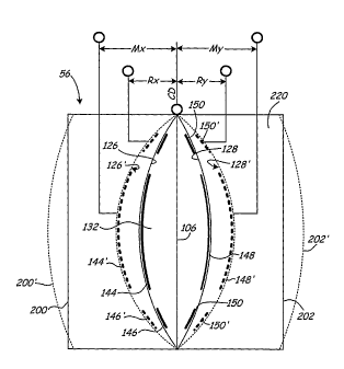
Figure 4 is a simplified cross sectional
view of pressure sensor 56 for use in illustrating
operation of the present invention.
Figure 5A is a graph of line pressure
versus primary sum effective gap and Figure 5B is a
graph of line pressure versus ring sum effective gap.
Figures 6A and 6B are graphs of line
pressure versus ring sum/primary sum and (ring
gap/primary gap)x+(ring gap/primary galD)y.
Figures 7A and 7B are three dimensional
graphs of line pressure versus primary transfer
function versus ring sum/primary sum.
Figure 8A is a graph of line pressure
versus ring sum/primary sum at various transfer
function values.
Figure 8B is a graph of slope x versus
nominal primary transfer function.
DETAILED DESCRIPTION
The present invention provides an apparatus
and method for determining line pressure for a multi-
electrode capacitance-based pressure sensor. By
computing the ratios of sums, or sums of ratios, of
appropriate capacitances in a multi-capacitance based
pressure sensor, the line pressure of the process
fluid can be determined.
CA 02609010 2007-11-16
WO 2006/130425 PCT/US2006/020254
-4-
Figure 1 shows generally the environment of a
process measurement system 32. Figure
1 shows
process piping 30 containing a fluid under pressure
coupled to the process measurement system 32 for
measuring a process pressure. The process measurement
system 32 includes impulse piping 34 connected to the
piping 30. The impulse piping 34 is connected to a
process pressure transmitter 36. A primary element
33, such as an orifice plate, venturi tube, flow
nozzle, and so on, contacts the process fluid at a
location in the process piping 30 between the pipes
of the impulse piping 34. The
primary element 33
causes a pressure change in the fluid as it passes
past the primary element 33.
Transmitter 36 is a process measurement device
that receives process pressures through the impulse
piping 34. The transmitter 36 senses a differential
process pressure and converts it to a standardized
transmission signal that is a function of the process
pressure.
A process loop 38 provides both a power signal
to the transmitter 36 from control room 40 and
bidirectional communication, and can be constructed
in accordance with a number of process communication
protocols. In the illustrated example, the process
loop 38 is a two-wire loop. The two-wire loop is used
to transmit all power to and all communications to
and from the transmitter 36 during normal operations
with a 4-20 mA signal. A computer 42 or other
information handling system through modem 44, or
CA 02609010 2007-11-16
WO 2006/130425 PCT/US2006/020254
-5-
other network interface, is used for communication
with the transmitter 36. A
remote voltage power
supply 46 powers the transmitter 36.
Figure 2 is a simplified block diagram of
pressure transmitter 36. Pressure transmitter 36
includes a sensor module 52 and an electronics board
72 coupled together through a databus 66. Sensor
module electronics 60 couples to pressure sensor 56
which received an applied differential pressure 54.
The data connection 58 couples sensor 56 to an analog
to digital converter 62. An optional temperature
sensor 63 is also illustrated along with sensor
module memory 64. The electronics board 72 includes a
microcomputer system 74, electronics memory module
76, digital to analog signal conversion 78 and
digital communication block 80.
In accordance with techniques set forth in
U.S. Patent No. 6,295,875 to Frick et al., pressure
transmitter 36 senses differential pressure. However,
the present invention is not limited to such a
configuration.
Figure 3 is a simplified cross-sectional
view of one embodiment of a sensor module 52 showing
pressure sensor 56. Pressure sensor 56 couples to a
process fluid through isolation diaphragms 90 which
isolate the process fluid from cavities 92. Cavities
92 couple to the pressure sensor module 56 through
impulse piping 94. A substantially incompressible
fill fluid fills cavities 92 and impulse piping 94.
When a pressure from the process fluid is applied to
CA 02609010 2007-11-16
WO 2006/130425 PCT/US2006/020254
-6-
diaphragms 90, it is transferred to the pressure
sensor 56.
Pressure sensor 56 is formed from two
pressure sensor halves 114 and 116 and filled with a
preferably brittle, substantially incompressible
material 105. A diaphragm 106 is suspended within a
cavity 132,134 formed within the sensor 56. An outer
wall of the cavity 132, 134 carries electrodes
146,144,148 and 150. These can, generally, be
referred to as primary electrodes 144 and 148, and
secondary or secondary electrodes 146 and 150. These
electrodes form capacitors with respect to the
moveable diaphragm 106. The capacitors, again, can be
referred to as primary and secondary capacitors.
As illustrated in Figure 3, the various
electrodes in sensor 56 are coupled to analog to
digital converter 62 over electrical connection 103,
104, 108 and 110. Additionally, the deflectable
diaphragm 106 couples to analog to digital converter
62 through connection 109.
As discussed in U.S. Patent No. 6,295,875,
the differential pressure applied to the sensor 56
can be measured using the electrodes 144-150. As
discussed below, the capacitance measured using these
electrodes can also be used to determine the line
pressure of the process fluid applied to the pressure
sensor 56.
Figure 4 is a simplified cross-sectional
view of sensor 56 used to illustrate operation of the
present invention. Figure 4
illustrates various
CA 02609010 2007-11-16
WO 2006/130425 PCT/US2006/020254
-7-
capacitive values, Mx between electrode 144 and
diaphragm 106, My between electrode 148 and diaphragm
106, Rx between electrode 146 and diaphragm 106 and
capacitor Ry between electrode 150 and diaphragm 106.
It has been discovered that during an
operation of pressure sensor 56, the line pressure
applied to the pressure sensor through the capillary
tubes 94 causes a deformation in the body 220 of
pressure sensor 56. The applied line pressure causes
a pressure difference between the pressure within
body 220 and the internal environment of the pressure
transmitter. This
pressure differential causes the
deformation in the body 220. In the example shown in
Figure 4, a greatly exaggerated deformation is shown.
Specifically, the applied line pressure causes
exterior walls 200 and 202 of body 220 to expand
outward to the positions shown in phantom at 200' and
202'. As the body deforms, the interior walls 126
and 128 of cavity 132, 134 also expand outward to the
position shown in phantom 126' and 128',
respectively. As the
walls 126 and 128 move
outwardly, the electrodes 144, 146, 148 and 150 also
move in an outwardly position as illustrated in
phantom at 144', 146', 148' and 150', respectively.
This change in position of the electrodes 144, 146,
148 and 150 results in a change in the capacitance
values as measured at Mx, My, Rx and Ry. In accordance
with the present invention, this change in
capacitance is used to measure the line pressure
applied to the pressure sensor 56.
CA 02609010 2007-11-16
WO 2006/130425
PCT/US2006/020254
-8-
As used herein, the capacitance between
electrodes 144 and 148 and the diaphragm 106 is
referred to as a "primary capacitance" and the
capacitance between electrodes 146 and 150 and the
center diaphragm 106 is referred to as a secondary
capacitance. In
accordance with the present
invention, the line pressure is determined as a
function of the capacitance of a primary capacitor
and the capacitance of a secondary capacitor. These
capacitance values can be used in a ratio of sums, or
sum of ratios, in a configuration to reduce errors in
the line pressure measurements.
A line pressure (P) signal can be derived
from the multi-electrode capacitance based
differential pressure sensor 56 described above.
This determination can be made by computing a ratio
of sums, or a sum of ratios of the appropriate
inverse active capacitance signals. As used herein,
active capacitance is that capacitance which responds
to movement of the center diaphragm (CD) relative to
the sensor cavity and excludes any stray capacitance.
The inverse of active capacitance is proportional to
the separation or gap between the two large area
(primary) electrodes separated by a relatively small
distance. The configuration illustrated above with a
center primary electrode and the ring secondary
electrodes can be used to determine line pressure
when the inverse active ring capacitances are divided
by the inverse active primary capacitances. More
CA 02609010 2007-11-16
WO 2006/130425 PCT/US2006/020254
-9-
specifically, line pressure can be determined as
follows:
LP=Ic*(111bc+11Ry)1(11Mx+11My) EQ. 1
A different, equally useful formulation can be
written as follows:
LP=j*(11Rx)1(11Mx)+(11Ry)1(11My)=P(Mx1Rx+MylRy) EQ. 2
Where M is the active capacitance of the primary
electrode, R is the active capacitance of the ring
electrode, x and y refer to the low and high sides of
the differential pressure sensor as illustrated in
Figure 4. The constants k and j are proportionality
constants. Line pressure can also be determined using
a single active capacitance value. However, in such
a configuration, the capacitance is particularly
sensitive to errors, for example, due to temperature
variations. In contrast, using the ratios discussed
above, a much greater signal to noise ratio can be
obtained, for example a factor 100 improvement over
the use of single active capacitance.
Figure 5A is a graph of line pressure (PSI)
versus primary sum-effective gap ( m) showing the
temperature effect on the sum of the gaps between the
primary electrodes 144, 148 and the diaphragm 106
utilizing inverse capacitance. Figure
5B is a
similar graph utilizing inverse ring capacitance. As
illustrated in FIGS. 5A and 5B, measuring the line
pressure with inverse capacitance provides a very
steep slope or low gauge factor with large changes in
apparent line pressure (y-intercept) for small
changes in temperature. Figure 6A is a graph of line
CA 02609010 2007-11-16
WO 2006/130425
PCT/US2006/020254
-10-
pressure versus ring sum/primary sum in accordance
with equation 1 at various temperatures and Figure GB
is a graph of line pressure versus (ring gap/primary
gap)x+(ring gap/primary gap)y in accordance with
equation 2. As illustrated in FIGS. 6A and 6B, and
in contrast to the graphs FIGS. 5A and 5B, the slope
of the LP signal is greatly reduced (higher gauge
factor) and the y-intercept offsets caused by
temperature are small relative to the LP span. The
raw temperature error in FIGS. 6A and GB is similar
to comparable sensors and is at least partially
correctable. In the graphs of FIGS. 5A, 5B, 6A and
6B, the data was collected at a differential pressure
of 0.
A line pressure signal can also be obtained
when the differential pressure and line pressure are
superimposed by combining either of the ratios
illustrated in equations 1 or 2 with a standard
differential pressure transfer function. In the case
of equation 1, such a combination results in a fit of
the data to a surface in three dimensional space with
line pressure being a function of a ratio from
equation 1 and the standard transfer function
(Mx - My)
. For example, FIGS. 7A and 73 are the views
(Mx + My)
of a graph of line pressure versus primary transfer
function versus ring sum/primary sum. In this
example, 192 data points are fitted based upon using
a standard pressure transmitter at various line
pressure and differential pressure values. The
CA 02609010 2007-11-16
WO 2006/130425
PCT/US2006/020254
-11-
reorientation of the axes in Figure 7E illustrates
the close fit of the data into a plane.
Figure 8A is a graph of the data from FIGS.
7A, 7B of line pressure versus ring sum/primary sum.
Figure 8B is a graph of the slope of each line in
Figure BA versus nominal primary TF. As illustrated
in these figures, the data is easily segregated with
great consistency by the transfer function. The plot
in Figure 8B illustrates that there is no higher
order effect that warps or twists the plane and
confirms the simplicity of the ratio/transfer
function/line pressure relationship.
With the present invention, the instability
of the dielectric constant of the fill fluid caused
by heating, cooling, compression, decompression and
transients cancels out to a relatively large degree.
This is achieved by using more than one electrode on
either side of the diaphragm in the pressure cell to
obtain the line pressure signal.
In specific experiments, the precision of
the data provides an error band of +1-70 PSI line
pressure at a 95% confidence level. This level of
precision is sufficient for reducing zero and span
line pressure errors by a factor of 10 over a
standard configuration by correcting the differential
pressure transmitter output based upon the line-
pressure signal.
Manipulation of the capacitance
data alone provides this improvement and no
additional line-pressure sensor is required.
Further, the present invention can be used to extract
CA 02609010 2013-08-29
=
-12-
a useable line pressure signal based upon the
measured capacitance values, again without the use of
an additional line pressure sensor. In more advanced
configurations, the line pressure signal can be used
in combination with differential pressure and, in
some configurations, combined with temperature to
provide a mass flow calculation.
In one example, the capacitance of the
primary capacitor changes by about 0.2% as the line
pressure changes from 0 to 2000 PSI. Similarly, the
capacitance of the ring capacitor changes by about
0.7% over such a range. The change in capacitance is
substantially linearly relative to the change in
applied line pressure. The two capacitances are used
to accurately measure the applied line pressure.
Although the present invention has been
described with reference to preferred embodiments,
workers skilled in the art will recognize that
changes may be made in form and detail without
departing from the scope of the invention.
In some embodiments the present invention includes
compensating the calculated line pressure based upon
the applied differential pressure. As used herein, the
"primary" electrodes and capacitors and "secondary"
electrodes and capacitors can be alternatively referred
to as "primary" and "secondary", respectively.
The measured or calculated line pressure can be used
independently, or can be used to, for example,
compensate for errors in the measured differential
CA 02609010 2007-11-16
WO 2006/130425
PCT/US2006/020254
- 13 -
pressure . It is contemplated that the measured line
pressure can be used for other purposes.