Note: Descriptions are shown in the official language in which they were submitted.
CA 02609611 2007-11-05
SPLIT CORE STATUS INDICATOR
CROSS-REFERENCE TO RELATED APPLICATIONS
[0001] Not applicable.
BACKGROUND OF THE INVENTION
[0002] The present invention relates to a device for indicating the operating
state of an
electrical load and, more particularly, to a device for monitoring electric
current in a cable
connecting a load and a power source.
[0003] Many industrial, commercial and residential environments incorporate
large
numbers of electrical loads that are widely distributed geographically and
often located in sites
where access is difficult. Many these devices are small and draw very limited
amounts of current,
often only a small fraction of an amp. However, the operation of these loads,
for example, small fan
motors or lights can be important to maintaining a safe environment or the
successful completion
of a process that may involve costly or hazardous equipment or materials.
Although desirable,
monitoring the operation of these devices is complicated by their remoteness
from the monitoring
location. In addition, these devices are often controlled by a controller that
is equally remote from
the monitoring location. For example, while security or maintenance personnel
may desire to
monitor the operation of a building's lights from a central location, the
lights of a commercial
building are commonly controlled by switches, photo-detectors, or motion
sensors located on the
floor or in the room where the light is located. Likewise, an operator of an
industrial process may
desire to monitor the operation of a number of widely distributed devices, for
example, the
operation of a heater and a fan located in an air duct and controlled by a
remotely located
thermostatic sensor.
[0004] The state of the switch controlling the operation of a load can
sometimes be
signaled to a remotely located monitoring station, but the additional wiring
and circuit complexity
often makes monitoring the state of the switch impractical. For example, a
second set of contacts
in the switch that controls the load could be used to activate a relay
signaling an open or closed
connection between a power source and a load. However, the cost a switch with
a second set of
contacts, a relay, and wiring to connect the relay to a remote monitoring
location is often
prohibitively expensive.
[0005] Remote signaling of the operating status of an electrical device is
commonly
provided by a status indicator comprising a current sensor that is
electromagnetically coupled to a
-1-
CA 02609611 2007-11-05
cable supplying power to the monitored electrical device or load. Baron et
al., U.S. Patent
No. 7,193,428, incorporated herein by reference, disclose a status indicator
comprising a current
sensor and a low threshold current switch. The status indicator includes a
current transformer
comprising an annular transformer core that encircles the power cable.
Fluctuating current in the
power cable produces a changing electro-magnetic field around the cable which,
in turn, induces a
magnetic flux in the core of the current transformer. The magnetic flux in the
core induces a
voltage in a wire winding that encircles the cross-section of the core. Thus,
the power cable is the
primary winding and the wire winding is the secondary winding of the current
transformer. The
secondary winding is connected a rectifier and a capacitor that is selected to
cause the circuit to
resonate at the expected frequency of the alternating current induced in the
secondary winding,
typically 50-60 Hz. The output of the resonant circuit, comprising the
secondary winding and the
resonating capacitor, is the input to a voltage multiplier. When a current is
present in the power
cable, a voltage is induced in the secondary winding which is multiplied in
the voltage multiplier
causing a pair of transistors of a current switch to conduct shorting the
output terminals of the
status indicator. When there is no current in the power cable, a voltage is
not induced in the
secondary winding and the switch transistors do not conduct, preventing
conduction between the
switch output terminals. The low threshold current switch is capable of
detecting currents less than
0.15 amps making the status indicator particularly useful for loads that draw
very limited currents.
[0006] The low threshold current switch can be implemented with either a solid
core current
transformer, as illustrated in U.S. Patent No. 7,193,428 or a split core
current transformer. Passing
the power cable through the central aperture of a solid core transformer
requires that the power
cable be disconnected so that the end of the cable can be inserted into the
aperture. This can be
particularly difficult when a status indicator is to be retrofitted to an
existing circuit and the most
desirable location of the device is between distantly located termini of the
power cable. Cota, U.S.
Patent No. 5,502,374, incorporated herein by reference, discloses a split core
current transformer
that enables engagement of a power cable without disconnecting the cable. The
hinged case
enables the halves of the toroidal core to pivoted apart. The cable can pass
between the open
ends of the core portions and then be secured in the central aperture of the
core by pivoting the
portions of the core back together. While a split core sensing transformer
facilitates installation,
particularly where it is difficult to pass a disconnected end of the cable
through the core's aperture,
the current transformer is quite large making it difficult to locate the
device in the small electrical
enclosures and spaces that often typify installations incorporating loads
having limited current
draws.
-2-
CA 02609611 2007-11-05
[0007] What is desired, therefore, is a very compact device for detecting and
indicating
the status of current flowing in an electrical conductor.
BRIEF DESCRIPTION OF THE DRAWINGS
[0008] FIG. 1 is a schematic illustration of an electrical circuit including a
remotely
controlled and monitored load.
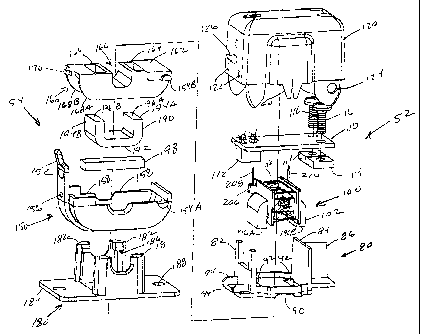
[0009] FIG. 2 is a perspective drawing of a status indicator.
[0010] FIG. 3 is a perspective drawing of the status indicator of FIG. 2. in
an open condition
to permit a cable to be situated in the area of the center aperture.
[0011] FIG. 4 is an exploded view of the status indicator of FIG. 2.
[0012] FIG. 5 is a perspective view of a transformer core segment and integral
bobbin.
[0013] FIG. 6 is a side view of a transformer core segment with integral
bobbin in a winding
fixture.
[0014] FIG. 7 is a schematic diagram of a low threshold current switch.
DETAILED DESCRIPTION OF PREFERRED EMBODIMENTS
[0015] Referring in detail to the drawings where similar parts are identified
by like reference
numerals and referring more particularly to FIG. 1, an exemplary electrical
system 20 includes an
electrical load 22 that is connected to a power supply 24 by power cables 26,
28. By way of
examples, loads may include valves, heaters, relays, lights, and motors that
drive pumps, fans, etc.
In the exemplary system, the load comprises a motor 21 that drives a fan 23.
The operation of the
motor of the exemplary system is controlled by a relay 30 which, in turn, is
controlled by a building
management controller 32. A status indicator 36 comprising generally a current
transformer to
sense current in a power cable and a current switch that is actuated by the
output of the current
transformer, monitors the current flow in one of the power cables. When the
fan motor 22 is
running and current is flowing to the fan motor in the power cable 26, the
status indicator provides
a first signal at the output terminals 38, 40 which are conductively connected
to the building
management computer and/or an annunciator 42 at a monitoring station 44 which
may be remote
from the building management computer and the elements of the monitored
electrical circuit.
When current flow ceases in the power cable 26, the status indicator provides
a second signal at
the terminals for the remote controller or the monitoring station indicating
that the fan motor is no
longer operating.
[0016] For ease of installation it is often desirable to install the status
indicator in an
electrical enclosure that houses another element of the circuit being
monitored. For example, the
-3-
CA 02609611 2007-11-05
status indicator 36 for the exemplary electrical circuit is located in the
same enclosure 46 as the
relay that controls power to the fan motor. On the other hand, it may be
desirable to co-locate the
current switch in an enclosure with the wiring connections to the motor or at
some other
intermediate point. Small enclosures are commonly utilized in association with
loads that draw
lower currents and even if the status indicator is located separately, it is
desirable that its size be
minimized to facilitate installation in walls, duct work or other close
environments. Moreover, to
facilitate installation, particularly when retrofitting an existing circuit,
it is highly desirable that the
status indicator include a split core current transformer. The size and cost
of a wire wound, split,
toroidal core current transformer is a substantial impediment to reducing the
size of a current
sensing status indicator.
[0017] The secondary windings of toroidal current transformers are typically
wound
directly on the toroidal core which may be coated or boxed with a dielectric
to insulate the core
from the conductor comprising the winding. On the other hand, the secondary
windings or coil of
so-called bobbin wound transformers are typically wound on a rigid,
insulating, pre-formed bobbin
that includes an aperture enabling the bobbin and the coil to be slipped over
a portion of the
transformer core. The bobbin maintains the coil's shape and size while the
coil is assembled on
the transformer core and insulates the winding from the core when the
transformer is assembled.
However, a bobbin wound coil is typically not used for current transformers,
even if the core
comprises separable segments, because the core is typically annular or an
annulated rectangle,
that is, a generally rectangular or square ring with a central aperture to
receive the power cable.
An enlarged bobbin and coil would be required to provide sufficient clearance
to slide the bobbin
over the curve or around the orthogonal corners of the core segment. The
present inventor
concluded that the size and cost of a current monitoring status indicator
could be substantially
reduced if the coil could be wound on a bobbin that was integral with a
portion of the current
transformer core.
[0018] Referring to FIGS. 2 and 3, the body of the status indicator 36 is,
generally, an
annular rectangular block with rounded corners and a center aperture 50
through which a power
cable can be passed. The status indicator comprises upper 52 and lower 54
portions that are
connected by a hinge 56 enabling relative rotation of the upper and lower
portions. By swinging
the upper portion away from the lower portion, a gap is created between the
portions, distal of the
hinge, enabling a power cable to be situated in the area of the center
aperture without the
necessity of disconnecting the cable. Once the cable is in place, the portions
of the status
indicator are rotated together, conjoining the portions and encircling the
power cable within the
center aperture. The position of the power cable in the center aperture is
restrained in a groove 58
-4-
CA 02609611 2007-11-05
in the end of a resilient finger 60 that projects from the upper portion of
the status indicator into the
vicinity of the center aperture.
[0019] Referring also to FIG. 4, the upper portion of the status indicator
comprises a
frame 80 and an upper housing 120. The frame comprises front 82 and back 84
walls and a
spine 86 that project normal to a bottom plate 88. The bottom plate is
generally planar with a
central depression 90 and includes a pair of apertures 92 adjacent,
respectively, to the front and
back walls. A circuit board 110 and a transformer core assembly 100 are
securable to the frame.
The upper housing 120 slides over and encloses the assembly comprising the
frame, circuit board
and transformer core assembly and is secured by interactions between a
plurality of projections 94
extending from the frame and corresponding apertures 122 in the upper housing.
A portion on
each side of the upper housing defines a hinge aperture 124 to receive,
respectively, a hinge pin
projecting from the lower portion.
[0020] The lower portion 54 of the status indicator 36 comprises a lower
housing 150 and a
cover 160. The lower housing is generally C-shaped in the elevation view with
a cantilevered latch
arm 152 projecting from one end. At the opposite end of the lower housing, a
semi-circular lower
portion of a hinge pin 154A protrudes from each side of the housing. The
depressed center of the
C-shaped housing defines a portion of the center aperture 50 of the status
indicator. The
cover 160 comprises a top plate 162 defining a pair of apertures 164 and
having a depressed
central groove portion 166 that aligns with the depressed center of the lower
housing. A
wall 168A, 168B projects normal to the top plate at either side of the cover.
A semicircular hinge
pin segment 154B projects laterally from either side of the cover. The lower
housing and cover are
assembled by sliding the walls of the cover between the walls of the lower
housing. One end of
the cover is securable in the lower housing by engagement of a projection 170
extending from the
end of the cover into a corresponding aperture 156 in the wall of the lower
housing.
[0021] The upper and lower housings, the cover and the frame preferably
comprise a
resilient, insulating material, such as acrylonitrile butadiene styrene (ABS)
plastic. To assemble
the upper and lower portions of the status indicator, the portions of the
lower housing and the cover
defining the hinge pins are aligned with the portions of the upper housing
defining the hinge
apertures, The portions of the status indicator are pressed together deforming
the resilient
material. When the hinge pins reach alignment with the hinge apertures in the
upper housing, the
resilient housings return to their undeformed shapes capturing the hinge pins
within their
respective corresponding apertures. The second end of the cover is secured to
the lower housing
by the simultaneous confinement of the hinge pin halves 154A, 154B of the
lower housing and the
cover in the hinge apertures 124.
-5-
CA 02609611 2007-11-05
(0022] The latch arm 152 projecting upward from the side of the lower housing
includes a
portion defining a latching aperture 156. When the hinged upper and lower
portions of the status
indicator are swung together to conjoin the sides distal of the hinge, the
latch arm engages a
stud 126 projecting from the surface of the upper housing causing the
cantilevered arm to deflect.
When the stud and the latching aperture reach alignment, the resilient latch
arm recovers and the
mating surfaces of the stud and aperture lock the upper and lower housings in
the closed position.
[0023] The status indicator preferably also includes a removable mounting base
180
providing one or more features for securing the device in an environment, for
example securing the
indicator to a surface, such as the wall of an enclosure, or engaging a mating
mounting
mechanism, such as a mounting rail. The mounting base preferably comprises a
plurality of
projecting arms 182 affixed to a mounting structure, for example a
substantially planar mounting
plate 184, and arranged to slide over the surface of the housing. Preferably,
each of the arms
includes a latching surface 186 that is arranged to engage a corresponding
engagement
surface 158 on the lower housing. To install the status indicator, the
mounting base is secured to a
surface or a mounting rail, for example with screws projecting through screw
apertures 188 in the
mounting plate. The lower housing of the status indicator is nested between
the projecting arms of
the mounting base and the body of the status indicator is pushed toward the
mounting plate.
When the latching surfaces of the arms are aligned with the respective
engagement surfaces on
the lower housing, the resilient arms rebound and mutual engagement of the
surfaces secures the
housing to the mounting base. The slidably engageable mounting base reduces
the size of the
status indicator and facilitates its installation by enabling unobstructed
access to the mounting
screws or other mounting or securing devices during installation of the
mounting base while
providing a mounting that is not substantially larger than the footprint of
the status indicator
housing.
[0024] The current transformer of the status indicator comprises the upper
transformer
assembly 100 and a lower transformer core segment 190. Referring also to FIG.
5, the upper
transformer assembly includes an upper transformer core segment 102 with an
integral bobbin 104
and a coil 106 comprising an electrical conductor and insulation that is wound
around a center
portion 200 of the bobbin. The upper and lower transformer core segments
comprise a
magnetically permeable material, for example a strip of grain oriented, 0.012
silectron, 3% silicon
steel. The magnetically permeable material is typically formed into a ring
that is generally
rectangular in shape with rounded corners. The ring is cut in half to form two
C- or U-shaped core
segments, each comprising a base portion 192 with a leg 194A, 194B projecting
substantially
normal to the base at each end of the base. When the end portions 196A, 196B
of the legs 194A,
-6-
CA 02609611 2007-11-05
194B of the two core segments are joined together, the combined core segments
form the annular,
rectangular core of the current transformer. An alternating current in a power
cable located in the
central aperture of the magnetically permeable transformer core produces an
expanding and
collapsing magnetic field around the cable that induces a varying magnetic
flux in the magnetically
permeable transformer core. The varying magnetic flux in the core, in turn,
induces an electric
current in a conductor that is wound around a cross-section of the ring-like
core.
[0025] An annular rectangular core can be very efficient enabling a physically
small
transformer core to induce a measurable current in the secondary winding at
low levels of power
cable current. However, the secondary winding or coil is typically wound
directly on the base of a
C-shaped transformer segment increasing the difficulty and the cost of
manufacturing the
transformer. The cost of a transformer can be reduced if the coil can be wound
on a bobbin which
is slipped over the core after winding. The bobbin preserves the shape of the
coil during assembly
and can insulate the conductor in the winding from the core. However, the
perpendicularly
projecting legs of a C-shaped transformer core segment make slipping a bobbin
wound core over
the base of the core segment impractical as a very large hole, and
consequently a very large coil,
is required to enable a bobbin to pass over the right angle corner at the
junction of the core's base
and leg. While a bobbin wound coil can be slipped over a leg of a U-shaped
transformer core, the
length of the leg or the diameter of the coil must be increased significantly,
increasing the size of
the transformer. The current inventor concluded, however, the advantages of a
bobbin wound core
could be obtained with a bobbin that is integral with the core segment and
includes a portion that
encircles the cross-section of the base of the C-shaped core.
[0026] The upper transformer core assembly 100 comprises a C-shaped core
segment 102
with a bobbin 104 that is affixed to the base portion of the core segment.
Preferably, the bobbin is
molded in place on the transformer core segment. The bobbin comprises an
electrically insulating
material and includes a tube portion 200 that encircles the substantially
rectangular cross-section
of the base of the transformer core segment and flanges 202, 204 that are
spaced apart on the
tube portion and which project normal to the tube. The flanges confine the
conductor and
insulating material when they are wound around the tube portion to form the
coil and provide
structures 206 for anchoring the ends of the winding conductor and
conductively connecting the
conductor to conductive posts 208, 210 that project upward from the flange.
[0027] Referring to FIG. 6, an offset winding fixture enables the conductor
220 of the
secondary winding to be wound around the tube portion 200 of the integral
bobbin 104. The
transformer core segment 102 with integral bobbin in place is secured in the
fixture 500. The
fixture 300 comprises, generally, a pair of engagement plates 304 that include
relieved surfaces in
-7-
CA 02609611 2007-11-05
their faces to receive the legs of the C-shaped transformer core segment and a
surface to engage
the base of the segment securing the core segment for rotation The engagement
plates are
constructed with a weights 304 that counter-balance the off-center weight
distribution of the C-
shaped core when it is rotated about the central axis 306 of the base on
shafts 308.
[0028] The inventor also concluded that the size of the status indicator could
be further
reduced by integrating a portion of the transformer core and the current
switch, including its output
terminals, in an assembly. In the status indicator 36, the upper transformer
core assembly
including the upper transformer core segment, integral bobbin and coil is
supported in the frame 80
by the flanges of the integral bobbin with the ends of the legs of the C-
shaped core projecting into
respective corresponding apertures 92 in the frame. The outwardly projecting
conductive
posts 208, 210 that are interconnected to the respective ends of the coil
conductor are inserted into
apertures in a circuit board assembly 100 and interconnected with conductors
on the circuit board.
The circuit board assembly includes a current switch 112 and a pair screw
terminals that enable
connection of wires leading to a remote annunciator or control device. The
screw terminals each
comprise a nut 114 that is prevented from rotating by interference with the
spine 86 on the frame
and a screw 116. Preferably, the threads of the screw are deformed to prevent
the disengagement
of the screw and the nut when connecting a wire to the terminal.
[0029] Although other current switches could be used with the split core
transformer,
Baron et al., U.S. Patent No. 7,193,428, incorporated herein by reference,
disclose a current switch
that is particularly suitable for monitoring power cable currents between
approximately 0.15 amps
and 200 amps. Referring to FIG. 7, the current switch 500 comprises a resonant
input section 502,
a voltage multiplier 504 and a switch 506. A diode clamp, comprising a pair of
zener
diodes 508, 510 connected in series with opposing forward biases and
collectively connected in
parallel with the secondary winding 106, and a resonating capacitor 512
provide signal conditioning
for the output of the secondary winding. The capacitor 512 is connected in
parallel with the
secondary winding and is selected to resonate at the expected frequency of the
alternating current
in the monitored power cable, 50-60 Hz in the U.S. The resonant circuit,
comprising the resonating
capacitor and the secondary winding, increases the amplitude of the voltage
signal at frequencies
adjacent to the resonant frequency and interferes with signals having
frequencies remote to the
resonant frequency providing a more distinct, higher voltage signal than that
available at the output
of the secondary winding and lowering the current threshold required to obtain
an output signal
from the current transformer. Resonance can be optimized at a low current
threshold because the
inductive reactance of the secondary winding varies with power level while the
capacitor produces
little effect at higher power levels. The capacitor 512 also smoothes the
secondary winding voltage
-8-
CA 02609611 2007-11-05
by charging during the portion of the electrical cycle where the voltage is
increasing and
discharging during the portion of the cycle when the voltage is decreasing,
reducing the difference
between the maximum and minimum voltages of the periodic voltage waveform.
[0030] The diode clamp controls voltage excursions in the secondary winding to
protect the
switch 506 from over-voltage and increase its operating range. The Zener
diodes of the diode
clamp limit the voltage in the secondary winding resulting from inrush current
at start up or when
operating at higher power cable currents, to protect the field effect
transistors (FETs) of the
switch 506. The Zener diodes provide a convenient clamping circuit and the low
reverse voltage
leakage of the diodes enables a lower switching threshold for the current
switch, but other
clamping circuits could be used to control the sensing transformer output.
[0031] The voltage signal output by the sensing transformer 502 is input to a
voltage
multiplier 504. The voltage multiplier effectively comprises two half-wave
rectifiers in series, each
rectifier comprising a diode and a capacitor in series with the secondary
winding of the current
transformer. During the positive half-cycle diode 514 conducts and charges the
capacitor 518 and
during the negative half-cycle the second diode 516 conducts to charge the
second capacitor 519.
While additional stages might be incorporated in the voltage multiplier to
further amplify the voltage
signal, the amplified voltage signal at the output of the single stage voltage
multiplier 504 is equal
to twice the voltage at the input to the voltage multiplier. To further reduce
the threshold of the
current switch, diodes exhibiting minimal forward voltage drop, such as
Schottky type diodes, are
preferable for the voltage multiplier. A resistor 520, in parallel with the
capacitors of the voltage
multiplier, functions as a fixed load to controllably discharge the capacitors
518, 519 in a
predetermined period.
[0032] When current is flowing in the power cable 26, the current transformer
generates a
voltage signal that is multiplied and rectified by the voltage multiplier. The
amplified voltage at the
output of the voltage multiplier is conducted to the gates and sources of the
switch
transistors 522, 524 to enable conduction between the respective sources and
drains of the
transistors. The output terminals of the current switch, T1 528 and T2 530,
conductively
connected, respectively, to the drains of the switch transistors, are shorted
producing a first signal
to a controller or other device conductively connected to the terminals.
Testing has demonstrated
that the low threshold current switch utilized in conjunction with a split
core sensing transformer
can be used to detect power cable currents less than 0.10 amps. If there is no
current flowing in
the power cable 26, no voltage is induced in the secondary winding 106 of the
current transformer
and conduction between the sources and drains of the switch transistors 522,
524 is blocked
presenting a second signal, an open circuit, to the attached controller or
monitoring device.
-9-
CA 02609611 2007-11-05
[0033] The lower transformer core segment 190 is supported in the lower
housing 150 by a
resilient member 198 with the ends 196A, 196B of the legs 194A, 194B
projecting up through
respective apertures 164 in the cover 160. When the upper 52 and lower 54
portions of the status
indicator are rotated to the closed position, the ends of the upper 102 and
lower 190 transformer
core segments are conjoined completing the formation of the annular
rectangular transformer core.
The performance of a split core transformer can be seriously degraded by a gap
between the ends
of the legs of the core. The resilient member 198 urges the ends of the legs
of the lower
transformer core into contact with the ends of the legs of the upper
transformer core to minimize
the gap between the segments and maximize the performance of the core.
[0034] The size of the status indicator for monitoring the current in a power
cable is
reduced by the integration a circuit board and terminals with a segment of the
current transformer
having a coil wound on a bobbin that is integral with the base of the C-shaped
core segment.
[0035] The detailed description, above, sets forth numerous specific details
to provide a
thorough understanding of the present invention. However, those skilled in the
art will appreciate
that the present invention may be practiced without these specific details. In
other instances, well
known methods, procedures, components, and circuitry have not been described
in detail to avoid
obscuring the present invention.
[0036] The detailed description, above, sets forth numerous specific details
to provide a
thorough understanding of the present invention. However, those skilled in the
art will appreciate
that the present invention may be practiced without these specific details. In
other instances, well
known methods, procedures, components, and circuitry have not been described
in detail to avoid
obscuring the present invention.
[0037] All the references cited herein are incorporated by reference.
[0038] The terms and expressions that have been employed in the foregoing
specification
are used as terms of description and not of limitation, and there is no
intention,
in the use of such terms and expressions, of excluding equivalents of the
features shown and
described or portions thereof, it being recognized that the scope of the
invention is defined and
limited only by the claims that follow.
-10-