Note: Descriptions are shown in the official language in which they were submitted.
CA 02609654 2007-11-23
WO 2006/127944 PCT/US2006/020319
MULTILAYER PAPER MACHINE FABRIC HAVING CROSS MACHINE DIRECTION YARNS MADE OF A
MATERIAL WHICH COUNTERS EDGE CURLING
BACKGROUND OF THE INVENTION
Field of the Invention
The present invention relates to the papermalcing arts. More
specifically, the present invention relates to forming fabrics for a forming
section of a paper machine.
Description of the Prior Art
During the papermaking process, a cellulosic fibrous web is formed
by depositing a fibrous slurry, that is, an aqueous dispersion of cellulose
fibers, onto a moving forming fabric in a forming section of a paper machine.
A large amount of water is drained from the slurry through the forming
fabric, leaving the cellulosic fibrous web on the surface of the forming
fabric.
The newly formed cellulosic fibrous web proceeds from the forming
section to a press section, which includes a series of press nips. The
cellulosic fibrous web passes tlvrough the press nips supported by a press
fabric, or, as is often the case, betweeu two such press fabrics. In the press
nips, the cellulosic fibrous web is subjected to compressive forces which
squeeze water therefrom, and which adhere the cellulosic fibers in the web to
one another to turn the cellulosic fibrous web into a paper sheet. The water
is accepted by the press fabric or fabrics and, ideally, does not return to
the
paper sheet.
The paper sheet finally proceeds to a dryer section, which includes at
least one series of rotatable dryer drums or cylinders, which are internally
heated by steam. The newly formed paper sheet is directed in a serpentine
path sequentially around each in the series of drums by a dryer fabric, which
holds the paper sheet closely against the surfaces of the drums. The heated
drums reduce the water content of the paper sheet to a desirable level through
evaporation.
CA 02609654 2007-11-23
WO 2006/127944 PCT/US2006/020319
It should be appreciated that the forming, press and dryer fabrics all
take the form of endless loops on the paper machine and function in the
manner of conveyors. It should further be appreciated that paper manufacture
is a continuous process which proceeds at considerable speeds. That is to
say, the fibrous slurry is continuously deposited onto the forining fabric in
the forming section, while a newly manufactured paper sheet is continuously
wound onto rolls after it exits from the dryer section.
Press fabrics also participate in the finishing of the surface of the
paper sheet. That is, press fabrics are designed to have smooth surfaces and
uniformly resilient structures, so that, in the course of passing through the
press nips, a smooth, mark-free surface is imparted to the paper.
Press fabrics accept the large quantities of water extracted from the
wet paper in the press nip. In order to fill this function, there literally
must be
space, commonly referred to as void volume, within the press fabric for the
water to go, and the fabric must have adequate permeability to water for its
entire useful life. Finally, press fabrics must be able to prevent the water
accepted from the wet paper from returning to and rewetting the paper upon
exit from the press nip.
Woven fabrics take many different fonns. For example, they may be
woven endless, or flat woven and subsequently rendered into endless form
with a seam.
The present invention relates specifically to the forming fabrics used
in the forming section. Forming fabrics play a critical role during the paper
manufacturing process. One of its functions, as implied above, is to form
and convey the paper product being manufactured to the press section.
However, forming fabrics also need to address water removal and
sheet formation issues. That is, forming fabrics are designed to allow water
to pass through (i.e. control the rate of drainage) while at the same time
prevent fiber and other solids from passing through with the water. If
drainage occurs too rapidly or too slowly, the sheet quality and machine
efficiency suffers. To control drainage, the space within the forming fabric
2
CA 02609654 2007-11-23
WO 2006/127944 PCT/US2006/020319
for the water to drain, commonly referred to as void volume, must be
properly designed.
Contemporary forming fabrics are produced in a wide variety of
styles designed to meet the requirements of the paper machines on which
they are installed for the paper grades being manufactured. Generally, they
comprise a base fabric woven from monofilament and may be single-layered
or multi-layered. The yarns are typically extruded from any one of several
synthetic polymeric resins, such as polyamide and polyester resins, used for
this purpose by those of ordinary skill in the paper machine clothing arts.
The design of forming fabrics additionally involves a compromise
between the desired fiber support and fabric stability. A fine mesh fabric
may provide the desired paper surface properties, but such design may lack
the desired stability resulting in a short fabric life. By contrast, coarse
mesh
fabrics provide stability and long life at the expense of fiber support. To
minimize the design tradeoff and optimize both support and stability, multi-
layer fabrics were developed. For example, in double and triple layer
fabrics, the forming side is designed for support while the wear side is
designed for stability, as well as drainage.
Essentially, multi-layer fabrics consist of two fabrics, the forming
layer and the wear layer, held together by binding yarns. The binding is
extremely important to the overall integrity of the fabric. One problem with
multi-layer fabrics has been that the binding yarns tend to alter the
contractive properties of the base fabric layers when the fabrics are placed
under tension. As a result, such fabrics often exhibit an upwards curling
along the edges when in use on a papermaking machine. This edge curl
effect is particularly noticeable in warp bound fabrics where the yarns
binding the fabric layers run in the machine direction (MD). Parameters
which impact this curling effect include the fabric's layer construction,
weave pattern, yarn materials and sizes, and any finishing processing
performed on the fabric. Various fabrics have been designed to limit edge
curl by controlling these parameters, but with limited success. Most
3
CA 02609654 2007-11-23
WO 2006/127944 PCT/US2006/020319
commonly, attempts have been made to control edge curl through the heat-
setting and stress treatments applied as part of the finishing process.
However, these treatments are difficult to control and are often not
permanent. Moreover, these treatments leave a characteristic out-of-plane
bulge between the edge and the body of the fabric.
The present invention provides a solution to this problem of edge curl
in warp bound forming fabrics. The present invention describes a multi-
layer fabric having cross-machine direction (CD) yarns made of materials
which counter the edge curl effect when placed under load.
SUMMARY OF THE INVENTION
Accordingly, the present invention relates to a forming fabric for use
in the forming section of a paper machine, although it may find application in
the pressing and/or drying sections of the paper machine.
The present fabric is a papermaking fabric having a top layer and a
bottom layer of interwoven machine direction (MD) yams and cross-machine
direction (CD) yarns bound together with warp binder yams. At least some
of the CD yarns are made of a material which generates a strong contractive
force when returned to room temperature after heat-setting. These CD yams
are positioned in the fabric such that the strong contractive force offsets
tension forces generated when the fabric is placed under load and which
typically result in an edge curl. An exemplary material for these CD yarns is
polybutylene terephthalate (PBT).
In a preferred embodiment, the fabric is a triple layer forming fabric
where the top layer is the forming side of the fabric and the bottom layer is
the wear side of the fabric.
Other aspects of the present invention include that at least some of
the yams may be one of polyamide yams or polyester yarns, some of the
yams may be monofilament yarns, and some of the yarns may have different
diameters and/or shapes.
4
CA 02609654 2007-11-23
WO 2006/127944 PCT/US2006/020319
The present invention will now be described in more complete detail
with frequent reference being made to the drawing figure, which is identified
below.
BRIEF DESCRIPTION OF THE DRAWINGS
For a more complete understanding of the invention, reference is
made to the following description and accompanying drawings, in which:
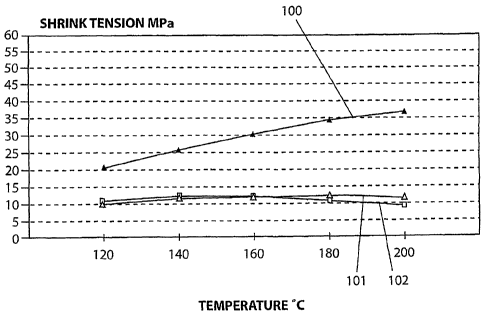
Figure 1 is a graph showing the shrink tension of PBT (polybutylene
terephthalate) at the beginning and end of heat treatment over a range of
temperatures and at room temperatures following treatment; and
Figure 2 is a graph showing the shrink tension of PET (polyethylene
terephthalate) at the beginning and end of heat treatment over a range of
temperatures and at room temperatures following treatment.
DETAILED DESCRIPTION OF THE PREFERRED EMBODIMENTS
As discussed above, multi-layer papermaking fabrics that contain
machine direction oriented yarns to connect the layers tend to run with the
edges curling strongly upwards when on the paper machine. This is because
the warp binder yarns impart different contractive properties to the separate
layers when under tension. As a result, the edges of the fabric curl upwards
when the fabric is placed under load. Fabrics that are optimized for all other
properties but still exhibit this edge curl when under load are not accepted
by
the market. Accordingly, there is a need to provide a permanent, opposing
effect to control curl in this class of fabrics. The present invention
strategically incorporates different yams materials having characteristics
that
can be used to counter the tension forces which cause edge curl in these
fabrics.
The present invention is intended to encompass both warp bound
fabrics and multi-layer fabrics bound with additional MD binder yams. In a
warp bound fabric, some of the MD yarns, which may be intrinsic to one or
both layers, cross between layers to at least bind with the other layer. These
5
CA 02609654 2007-11-23
WO 2006/127944 PCT/US2006/020319
warp binder yams are often paired such that the two yams combine to
produce a complete weave pattern (e.g. plain weave pattern, etc.) in one or
both of the layers.
A preferred embodiment of the present iiivention is a papermaking
fabric which incorporates CD yams made of materials, such as polybutylene
terephthalate (PBT), which when annealed under tension generate a strong
contractive force when returned to room teinperature. By properly
positioning these different material yams in the fabric, their strong
contractive forces can be used to offset the tension forces which cause edge
curling when the fabric is placed under load.
Accordingly, desirable materials for use in the present invention
should exhibit a strong contractive force when returned to room temperature
after heat-setting (annealing under MD tension). An exemplary material
exhibiting this characteristics is PBT. Figure 1 is a graph showing the shrink
tension of PBT (polybutylene terephthalate) at the beginning 101 and end
102 of heat treatment over a range of temperatures and at room temperatures
following treatinent 100. The shrink tension is a measure of the contractive
force of the material. For comparison, Figure 2 shows the shrink tension of
PET (polyethylene terepllthalate) at the beginning 201 and end 202 of heat
treatment over a range of temperatures and at room temperatures following
treatment 200. Note that following treatment, the PET material has a low
shrink tension whereas the PBT material has a signnificantly higher shrink
tension. A PBT yam, like Teijin 936B (the material shown in Figure 1),
when annealed under tension, generates a strong shrinkage force when the
annealing heat is removed. This force causes the PBT yam to contract,
iinparting a strong curl into any fabric it is woven into. For this reason,
prior
art papermaking fabrics do not typically use PBT as a yam material.
However, by strategically positioning PBT yarns in a fabric, the
present inveintion uses this contractive force to oppose the natural edge curl
under tension seen in warp bound structures. Such PBT yams, when
incorporated as some or more of the CD yarns, impart a balancing curl to the
6
CA 02609654 2007-11-23
WO 2006/127944 PCT/US2006/020319
freed edges of the fabric. Preferably the PBT yarns are used as CD yarns,
however different materials may be used for any of the yarns which comprise
the fabric.
Another aspect of the invention is that different material yarns can be
blended with other yarns and yarns materials to control the offset effect. For
example, if the countering forces generated by the PBT yarns are too strong,
the offset effect can be moderated by alternating PBT yarns with standard
material yarns, like polyethylene terephthalate (PET) or a polyamide (PA).
These different material yarns may be alternated at various ratios; such as
1 PBT : I PA, 1 PBT: 3 PA, IPBT: 1PET: IPA, I PBT: 1PET : 2PA woven
as PBT: PA: PET: PA, 2 PBT : 3 PA, etc. The effects of PBT may also be
moderated by co-polymerizing or blending other materials into the yarn. For
example, PET is a suitable/compatible blend with PBT. Since, PBT also has
better wear resistance than PET, the yarns formed by combining these two
materials will have increased wear resistance and thus the fabric produced
using these yams will have better wear resistance in addition to its edge curl
resistance. Blends of 85% PBT and 15% PET respectively by weight should
give reduced shrinkage force upon cooling, but still generate enough force to
avoid edge curling of the fabric. Blends containing 20% or more PET by
weight should not cause fabrics to curl, but still retain a high level of the
improved abrasion resistance of the PBT. In this regard, other possible
blends of 60% to 90% PBT and of 10% to 40% PET by weight are
envisioned. Furthermore, the combination of PBT and PET should not lead
to fibrillation and high pressure shower resistance problems that are often
seen in other polymer blend monofilaments.
Monofilaments produced from blends of PET or PBT with elastomers
for use in improving fabric abrasion resistance are very soft and are badly
deformed during heatsetting of fabrics, causing unwanted loss of fabric
permeability. They also have poor high pressure shower resistance. The
PBT/PET monofilaments of the present invention should not flatten to the
same extent. Polyamide monofilaments used in paper machine clothing are
7
CA 02609654 2007-11-23
WO 2006/127944 PCT/US2006/020319
susceptible to chemical attack and increase paper machine drive loads.
However, this is not the case in a fabric containing the PBT/PET
monofilaments of the present invention and there should be no loss in fabric
abrasion resistance in the case of fabrics containing alternating PET/PBT and
alternating PET/(PBT/PET 85/15 blends respectively by weight). The
abrasion resistance of fabrics of alternating PET/PA when compared to that
of 100% PET fabrics should be better. Blends of PBT/PET with low
shrinkage effects may be used 100% on the wear-side of fabrics, which may
match or exceed the performace of alternating PET/PA. Other materials
could also be blended with PBT to produce a desirable shrinkage behavior.
The fabrics according to the present invention preferably comprise
only monofilament yarns. Additionally, the CD yarns and MD yarns in the
forming side and wear side may have different diameters. It is preferable for
the forming side CD and MD yarns to have smaller diameters than the wear
side CD and MD yams. However, various combinations of yam diameters
can be used in the present invention. Further, in addition to a circular cross-
sectional shape, one or more of the yams may have other cross-sectional
shapes such as a rectangular cross-sectional shape or a non-round cross-
sectional shape. As discussed above, any suitable combination of materials
may be used as identified by one of ordinary skill in the art. Also, the
location of such CD yarns in the fabric, such as wear side, forming side,
either or both, may vary depending upon the application. Note, these
examples are simply representative examples of the invention and are not
meant to limit the invention.
Modifications to the above would be obvious to those of ordinary
skill in the art, but would not bring the invention so modified beyond the
scope of the present invention. The claims to follow should be construed to
cover such situations.
8