Note: Descriptions are shown in the official language in which they were submitted.
CA 02609919 2007-11-27
- 1 -
SYSTEM AND METHOD FOR PAYOUT OF COINS
FROM MULTIPLE COIN STORAGE UNITS
BACKGROUND ART
The invention relates to a change dispenser having multiple coin
storage units for use in automatic point of sales transactions. Many
methods of paying out change using multiple storage units (such as
tubes) utilize a motor to dispense with one or more solenoids to select
the particular coin tube. Another method widely employed is the use of
three solenoids to dispense from three coin tubes. Still others use a
motor that dispenses two different denominations depending upon the
direction the motor is operated.
Another method employed is by using one motor to provide the
selection of one of several coin tubes and then using a second motor to
dispense the selected coin. A still further system utilized a solenoid to
operate a stepper selector that selects a particular coin tube and then
using a motor or solenoid to dispense the selected coin.
It would be advantageous to provide a coin payout method that
would dispense from multiple coin storage units providing for the
required number of denominations and with large capacity. It would also
CA 02609919 2007-11-27
WO 2006/130875
PCT/US2006/021649
- 2 -
be advantageous to provide a coin payout method that would allow
more than one denomination to be dispensed from a coin storage unit
without any mechanical modification or adjustments. Another
advantage would be to provide a method of coin dispensing from
multiple coin storage units that would reduce costs and space by using
only one actuator.
SUMMARY OF THE INVENTION
The present invention provides a device for the payout of coins
comprising a plurality of coin storage units, a plurality of coin discharge
members, and an endless element having an engagement pin. Each
coin storage unit has a coin discharge member located at one end of the
coin storage unit. The coin discharge members are each physically
adapted to rotate about a pivot point such that when the coin discharge
members are rotated in a first direction the coin discharge members
cause a coin to be ejected from its respective coin storage unit. When
the coin discharge members are rotated in a second direction a coin is
not discharged from its respective coin storage unit. The endless
element and engagement pin are physically arranged to allow the
engagement pin to rotate the coin discharge members in the first
direction when the endless element is rotated in a first direction and to
rotate the coin discharge members in the second direction when the
endless element is rotated in a second direction.
CA 02609919 2007-11-27
WO 2006/130875
PCT/US2006/021649
-3 -
BRIEF DESCRIPTION OF THE DRAWINGS
FIG. 1 is a bottom perspective view of a coin payout device
according to an embodiment of the present invention;
FIG. 2 is a bottom perspective view of a coin payout device
according to an embodiment of the present invention illustrating coin
discharge;
FIG. 3 is an enlarged perspective view of a coin discharge member
according to an embodiment of the present invention;
FIG. 4 is a side view of the two rows of coin storage units according
to an embodiment of the present invention;
FIG. 5 is a top perspective view of a coin discharge member
according to an embodiment of the present invention;
FIG. 6 is a side view showing the relationship of a coin discharge
member with a stack of coins to be discharged according to an
embodiment of the present invention;
FIG. 7 is an enlarged perspective view of an optical coupler and
drive sprocket according to an embodiment of the present invention;
FIG. 8 is a bottom view of a coin payout device with the optical
coupler and drive sprocket situated at the bottom thereof according to
an embodiment of the present invention; and
FIG. 9 is a drawing showing a typical spring arrangement for
returning the coin discharge member to its first operating position
according to an embodiment of the present invention.
CA 02609919 2007-11-27
WO 2006/130875
PCT/US2006/021649
- 4 -
DETAILED DESCRIPTION OF THE PREFERRED EMBODIMENT
Referring now to the drawings, wherein like numerals refer to like
items, number 10 identifies a preferred embodiment of a coin payout
device having multiple storage units constructed according to the
clockwise about dowel 45 thereby causing the coin discharge member
pin 43 to push out the lowermost coin in the storage unit 22. A motor 50
turns drive sprocket 48 via a gearbox 52 (FIG. 5) to control the endless
element 44. idler sprockets 54, 56 and 58 are used to maintain the
In FIG. 2 the coin discharge member 38 is shown in a discharge
position after the engagement pin 46 has moved to the right and a coin
has been discharged from the storage unit 22. At this point, because
the coin discharge members 28 through 42 are located in the path of the
CA 02609919 2007-11-27
WO 2006/130875
PCT/US2006/021649
- 5 -
engagement pin 46, the endless element 44 is moved from its resting
position shown in FIG. 1 to the discharge position to discharge a coin
with the coin discharge member pin 43. The coin discharge member 38
is moved back to its resting position of FIG. 1 by urging the coin
discharge member 38 with the engagement pin 46. The coin discharge
member 38 may also be biased back to its resting position by a spring,
as described below. A curved slot 62 in the base 64 of coin storage unit
22 allows the discharge member pin 43 to drive out the bottom coin as it
is rotated approximately 60 degrees.
In FIG. 3 the coin discharge member 38 is shown in greater detail
with the coin discharge member pin 43 attached thereto and the
mounting dowel 45 that extends therethrough. Projections 66 and 68
extend to define surfaces 70 and 72 with a cavity that engages the
engagement pin 46 of the endless element 44 to discharge a coin, as
well as surfaces 74 and 76 to return the coin discharge member 38 to its
resting position.
Because the coin discharge members 28 through 42 are located in
the path of the engagement pin 46, for the engagement pin 46 to move
past the coin discharge member 28 through 42 without dispensing a
coin, the pin 46 must move clockwise with respect to FIG. 2 to not
engage the surfaces 70 and 72 thereby ejecting a coin. In this manner,
the pin 46 strikes the surfaces 78 and 80 (FIG. 3) of the coin discharging
members 28 through 42 and causes the coin discharge member, for
example coin discharge member 38, to move counterclockwise about its
CA 02609919 2007-11-27
WO 2006/130875
PCT/US2006/021649
- 6 -
dowel 45 thereby pushing the discharge member pin 43 away from the
opening of coin storage unit 22. As such, a coin is not ejected and the
pin 46 may be moved to the appropriate coin storage unit 12 through 26
for the ejection of the appropriate coin.
FIG. 4 shows two coin storage units 12 and 20. The larger coin
denomination storage unit 20 is shown in front of coin storage unit 12. It
can be understood from FIG. 4 that coin storage units 12, 14, 16 and 18
comprising a first row of coin storage units eject coins from a higher
position 82 than coin storage units 20, 22, 24 and 26 comprising a
second row, which eject coins at a lower position 84. This prevents
interference by coins with the opposite row of coin storage units during
payout.
The perspective view of FIG. 5 shows the placement of the motor
50 and its gear box 52 with respect to the coin storage units 12 through
26, the endless element 44, drive sprocket 48, and the coin discharge
members 28 through 42. An opening 86 is provided for coins that are
accepted from a depositor that are not to be directed into storage units
12 through 26 for payback. The opening 86 extends through the device
10 such that the coins may be held in a coin hopper (not shown) that is
located below the device 10. The motor 50 can be a DC motor that can
operate clockwise and counterclockwise by reversing the applied
voltage polarity, as is commonly known, or it can be a stepper motor that
can rotate in either direction by the known methods of applying pulse
trains to the coils thereof.
CA 02609919 2007-11-27
WO 2006/130875
PCT/US2006/021649
- 7 -
In FIG. 6, a side view of a stack of coins 88 is shown with its
lowermost coin 90 being discharged by a pin 43 of the discharge
member 38, which is being driven by the engagement pin 46 of the
endless element 44. The height of the pin 43 is selected such that it
comes to an elevation slightly lower than the top of the lowermost coin
90 such that when it moves to eject a coin, it only ejects a single coin.
If the motor 50 is selected to be a DC motor, an optical coupler 92
(FIG. 7) can be positioned to detect teeth 94 of the drive sprocket 48 as
they interrupt its optic path thereof as the endless element 44 is driven.
In this manner a processor controlling the device 10 can determine the
position of the pin 46 in order to direct it to the desired coin storage unit
12 through 26. Other techniques are well known, such as using a shaft-
encoded wheel in the motor drive system, a magnetically operated Hall
Effect device, and other position determining methods.
If the motor is selected to be a stepper motor, an optical coupler is
unnecessary, as a stepper motor is moved a precision rotation by a train
of electrical pulses. Thus the location of the pin 46 is calculated by the
number of pulses applied to the stepper motor.
FIGS. 7 and 8 show the placement of the optical coupler 92 with
respect to the drive sprocket 48 and the relationship to the endless
element 44 and its engagement pin 46. In this illustration, each
interruption of the optical path of the optical coupler 92 by sprocket teeth
94 will equal a movement of predetermined length of the endless
element 44. Other embodiments utilizing timing belts, plastic or metal
CA 02609919 2007-11-27
WO 2006/130875
PCT/US2006/021649
- 8 -
drive chains, cable chains, as well as 3-D belts are within the scope of
the present invention.
Turning now to both FIGs. 8 and 9 a coin discharge member 34
having a sprocket 48 and a coin discharge member pin 43 is shown with
a spring 96 placed around the sprocket 48 of the coin discharge
member 34. A first end 98 of the spring 96 engages a first boss 100
and a second spring end 102 engages a second boss 104, which is
attached to the base 106 of the coin payout device 10. A spring 92 may
or may not be used in combination with engagement pin 46 to return the
coin discharge members 28 through 42 to their resting positions.
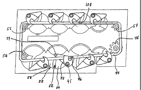
Referring back to FIG. 2, a second engagement pin 108 is located
across from the engagement pin 46 on the endless element 44 such
that it is at a position that it will not engage coin discharge member 28
through 42 while the engagement pin 46 is contacting a coin discharge
member 28 through 42. In this manner, the processor operating the
device can use either pin 46 or 108 to discharge coins. This saves time
in discharging coins by preventing the pin 46 from having to be rotated a
full revolution of the endless member 44 to eject a coin from a coins
storage unit 12 through 26. Depending on the space requirements for
operation and placement of the coin storage units, additional
engagement pins can be utilized.
It is contemplated that the identity of engagement pin 46 can be
distinguished from engagement pin 108 by making one of the pins 46 or
108 magnetic and detecting the magnetic pin with a magnetic sensor.
CA 02609919 2007-11-27
WO 2006/130875
PCT/US2006/021649
- 9 -
Determining the identity of the pin 46 and 108 allows for easier zero-
positioning of the endless element 44 between payout cycles.
From all the foregoing it is to be understood that the use of this
multiple coin storage payout method is not limited to a coin changer for
use in a vending machine or in an attended or unattended point of sale
location, but can be used in any application where coins are to be
dispensed. lt should also be understood that the number of coin
storage units and the arrangement thereof could be varied according to
space and other requirements.