Note: Descriptions are shown in the official language in which they were submitted.
CA 02610048 2007-11-28
WO 2006/128308
PCT/CA2006/000923
AUTOMATED AUTONOMY INCREASING SYSTEM
AND METHOD FOR COMMUNICATION DEVICES
BACKGROUND OF THE INVENTION
Field of the Invention
The present invention is related to the field of increasing autonomy life of
personal communications devices. More specifically, it relates to shutting
down
the personal communications device when the user is in or out of a pre-
determined zone.
Description of the Prior Art
An increasing number of people want their children to have a cellular
phone or another personal communication device for safety reasons. In
parallel,
more and more personal communication devices are used as tracking devices for
people with different cognitive problems. These communications devices are,
typically, to be used when the users are outside their homes.
Personal communications devices do not have a very long battery life.
Recharging the device repeatedly may not be a priority for young or disabled
users. The devices are therefore often automatically put in a shut down mode
caused by lack of energy in the batteries.
In order to solve this problem, some users have taken the habit of turning
off their cellular phones as soon as they enter their home and turning it back
on
as soon as they leave their home. Some even benefit from a call forward
feature
in which when the device is turned off, all calls are forwarded to a land line
(typically, that of their home). The user must have the discipline to turn on
and off
his device and must not forget to turn it on or off, even when distracted.
Often,
the cellular device will stay turned off for days before the user realizes he
forgot
to turn it back on or will stay on for days before entering a shut down mode
cause
by lack of energy in the batteries. Another problem is that people with
cognitive
CA 02610048 2013-11-27
WO 2006/128308
PCT/CA2006/000923
problems or children do not always have the knowledge or the capacity to turn
on and off their phone.
SUMMARY
In accordance with a first broad aspect of the present invention, there is
provided a method for automatic powering on and turning off of a
communications device, comprising: defining a critical zone to be one of
within or
outside a range of a base station transceiver; sending a location message from
one of the communications device and the base station transceiver; responding
to the location message if the communications device is within the range;
defining
a location of the communications device to be within the range if the
responding
occurs; and triggering the communications device to one of powering on and
turning off using the critical zone and the location of the communications
device.
In accordance with a second broad aspect of the present invention, there
is provided a system for automatic powering on and turning off of a
communications device, comprising: a base station transceiver having a range
and comprising: a zone definer for defining a critical zone to be one of
within or
outside the range; a base station transmitter for transmitting a message to a
communications device; a base station receiver for receiving a message from
the
communications device; and a communications device comprising: a device
transmitter for transmitting a message to the base station; a device receiver
for
receiving a message from the base station; a location determiner for defining
a
location of the communications device to be within the range if a message is
received by the device receiver from the base station transmitter; a state
modifier
for triggering the communications device to one of powering on and turning off
using the critical zone and the location of the communications device.
In accordance with a general aspect, there is provided a method for
automatic powering on and turning off of a communications device for
communication through a telecommunication network and having an add-on
transceiver operatively connected thereto. The method comprises : defining a
critical zone to be one of within or outside a range of a base station
transceiver;
sending a location message from one of said add-on transceiver of said
- 2 -
CA 02610048 2013-11-27
WO 2006/128308
PCT/CA2006/000923
communications device and said base station transceiver; responding to said
location message from the other one of said add-on transceiver of said
communications device and said base station transceiver if said add-on
transceiver of said communications device is within said range; defining a
location of said communications device to be within said range if said
responding
occurs; and triggering said add-on transceiver to one of powering on and
turning
off said communications device using said critical zone and said location of
said
communications device, wherein the communications device is prevented from
communicating through the telecommunication network when turned off and the
communications device communicates with the telecommunication network when
powered on and said add-on transceiver of said communications device
communicates with the base station transceiver when the communications device
is turned off and powered on.
In accordance with another aspect, there is provided a system for
automatic powering on and turning off of a communications device for
communications through a telecommunication network. The system comprises: a
base station transceiver having a range and comprising: a zone definer for
defining a critical zone to be one of within or outside said range; a base
station
transmitter for transmitting a message to the communications device; a base
station receiver for receiving a message from said communications device; the
communications device; and an add-on transceiver operatively connected to the
communications device and including: a device transmitter for transmitting a
message to said base station receiver; a device receiver for receiving a
message
from said base station transmitter; a location determiner for defining a
location of
said communications device to be within said range if a message is received by
said device receiver from said base station transmitter; and a state modifier
for
triggering said communications device to one of powering on and turning off
using said critical zone and said location of said communications device, said
device transmitter and said device receiver of said add-on transceiver
communicating with said base station transceiver when said communications
device is powered on and turned off and said communications device being
- 2a -
CA 02610048 2013-11-27
WO 2006/128308
PCT/CA2006/000923
prevented from communications through the telecommunication network when
turned off.
In accordance with a further aspect, there is provided a system for
automatic powering on and turning off of a communications device. The system
comprises: the communications device including a first transceiver for
communication through a telecommunication network and an add-on second
transceiver; and a base station transceiver having a range and including: a
zone
definer for defining a critical zone to be one of within or outside said
range; a
base station transmitter for transmitting a location message to the add-on
second
transceiver of the communications device; a base station receiver for
receiving a
location message from the add-on second transceiver of the communications
device; the add-on second transceiver including: a device transmitter for
transmitting the location message to the base station receiver; a device
receiver
for receiving the location message from the base station transmitter; a
location
determiner for defining a location of the communications device to be within
said
range if a message is received by the device receiver from the base station
transmitter; and a state modifier for triggering the communications device and
the
first transceiver to one of powering on and turning off using said critical
zone and
said location of the communications device, the device transmitter and the
device
receiver of the add-on second transceiver communicating with the base station
transceiver when the communications device and the first transceiver are
powered on and turned off, the first transceiver being prevented from
communicating through the telecommunication network and with the base station
transceiver when turned off and the first transceiver of the communications
device communicating through the telecommunication networks when powered
on.
In accordance with still a further aspect, there is provided a method for
automatic powering on and turning off of a communications device having a
first
transceiver for communication through a telecommunication network and an add-
on second transceiver operatively connected thereto. The method comprises:
defining a critical zone to be one of within or outside a range of a base
station
transceiver; sending a location message from one of the add-on second
- 2b -
CA 02610048 2013-11-27
WO 2006/128308
PCT/CA2006/000923
transceiver of the communications device and the base station transceiver;
responding to said location message from the other one of the add-on second
transceiver of the communications device and the base station transceiver if
the
add-on second transceiver of the communications device is within said range;
defining a location of the communications device to be within said range if
said
responding occurs; and triggering the add-on second transceiver to one of
powering on and turning off the communications device and the first
transceiver
using said critical zone and said location of the communications device,
wherein
the first transceiver is prevented from communicating through the
telecommunication network and the base station transceiver when turned off and
the communications device communicates with the telecommunication network
through the first transceiver when powered on.
The term "Personal communications device" is intended to include a
cellular telephone, a mobile device, any type of personal digital assistant
with
communications abilities, such as a Blackberry(TM) by RIM, or any other device
able to communicate and portable enough to be carried by a user, etc.
- 2c -
CA 02610048 2013-11-27
WO 2006/128308
PCT/CA2006/000923
BRIEF DESCRIPTION OF THE DRAWINGS
Further features and advantages of the present invention will become
apparent from the following detailed description, taken in combination with
the
appended drawings, in which:
Fig. 1. is an illustration of a home with its associated zones;
Fig. 2 is an illustration of a base station with a plurality of associated
zones;
Fig. 3 is an illustration of the communication between the transmitter of the
personal communications device and the base station of the preferred
embodiment;
Fig. 4 is an illustration of the connection between the transmitter and the
personal communications device;
Fig. 5 is an illustration of the main components of the system of the
preferred embodiment used to trigger a shut down or a power on of the personal
communications device;
Fig. 6 is a detailed circuit diagram for the electronics of the
microcontroller
of the transmitter;
Fig. 7 is an illustration of a microcontroller Microchip PIC18F4520 QFN 44
pins; and
Fig. 8 is an illustration of a transceiver Nordic nRF2401.
It will be noted that throughout the appended drawings, like features are
identified by like reference numerals.
DETAILED DESCRIPTION
The autonomy of the device is increased by creating a zone in which a
personal communications device will be automatically turned on or off.
The system enables automatic on/off of a standard communications device
based on the presence of a predefined Radio Frequency (RF) signal in the air.
A
RF signal can typically be received even through walls and windows and has
proven particularly useful in the present application although other types of
- 3 -
CA 02610048 2007-11-28
WO 2006/128308
PCT/CA2006/000923
wireless communication means can be contemplated without departing from the
invention.
The system has two main components, namely a base station transceiver
and an add-on transceiver for the communications device.
A shut down zone will be determined to be within or outside of a
communications range of the base station transceiver. Preferably, the base
station will be at the user's home and the shut down zone will be the zone
within
the ranger of the base station transceiver. However, one will readily
understand
that a plurality of zones could be created for each device and that it might
be
useful to create a shut down zone which is outside the range of the base
station
instead of within. Other examples would be the following: shut down the device
when the employee has left the workplace, thereby allowing use of the device
only on the workplace's premises during work hours, shut down the device when
the patient is within the hospital grounds, shut down the device when the
mentally
ill patient is within the care center's premises, shut down the device when
the kid
is either at home or at school, shut down the device when the kid is either at
his
mother's or at his father's home, etc.
In the case where the shut-down zone is a user's home, the user will
typically spend 10-12 hours of his day at home and will benefit from an
automatic
shut-down and power on of his device at the time of transitioning between the
outside and the inside of the zone. Since that is almost half a day, the
battery life
could be extended by as much as 200 % if the user did not take the time to
shut
down the device when arriving at home prior to using this system and will
prevent
any forgetting of turning on or off the device after a manual change.
In this same example, the preferred shut-down zone will have a radius of
to 50 m around the home of the user. That zone is shown as zone 2 (in dotted
lines) in Fig. 1. When the device is outside zone 2, either within zone 1 and
zone
2 or outside zone 1, the device will be turned on. If the device is within
zone 1,
the device will be turned off. Preferably, when the device is turned off, a
call
30 forward
feature of the device, if any, will be activated and the calls to the device
will be forwarded to another number, typically to the land line of the home.
- 4 -
CA 02610048 2007-11-28
WO 2006/128308
PCT/CA2006/000923
Typically, the zones will be circular since a RF transceiver has a circular
range. However, deformation of the RF waves will cause the circles to be less
than regular, the zone's shape being that of an approximate circle*. The base
station transceiver will be at the center of the zone. Therefore, if the base
station
transceiver is placed at one extremity of the home building, it is possible
that the
zone will be larger near that extremity and smaller near the opposing
extremity.
Ideally, the transceiver should be placed near the center of the building.
Fig. 2 shows the zones defined around a base station and illustrates the
propagation of the RF waves around the base station, even through walls. The
circles are shown to be perfectly round whereas, in reality, the shape of the
circles would be deformed. The house perimeter is delimited by rectangle 5. In
this particular case, the base station transceiver 4 is located near one
corner of
the house perimeter and does not have a very broad range. Positions 6 and 7
are
within the zone of range of transceiver 4 because the RF waves are able to
propagate that far. They are therefore identified as being within ("in") the
zone.
Position 8 is outside of the transceiver's range, no RF wave is able to reach
position 8 and it is therefore identified as being outside ("out") of the
zone.
Preferably, as long as the device stays within the zone, the device will not
be automatically turned on and off repeatedly. Instead, the trigger to turn
the
device on or off will be done upon detection of a change in the state of the
device, from in to out or from out to in. In Fig. 2, crossing the external
circle
shown would trigger the turning on or off of the device, depending on the type
(shut down or power on) of zone defined for the transceiver 4. Depending on
the
frequency of verification of the location of the device, if the user was to
stay for an
extended period of time on the limit of the zone (which is, as one will
readily
understand, not a physical barrier but an invisible limit), it would be
possible for
the device to alternate between the power on and shut down states each time
the
location of the device is checked. However, it will be assumed that the user
will
not prolong his stay on the boundary of the zone for more than the time
between
each verification of the location of the device.
Referring now to Fig. 3, the base station 9 is a transceiver able to send a
RF signal to a communication device add-on 10 which is also a transceiver. Add-
- 5 -
CA 02610048 2007-11-28
WO 2006/128308
PCT/CA2006/000923
on transceiver 10 is connected to communication device 11, either permanently
or temporarily. It could also be integrated within the communications device
housing. Both the base station 9 and the transceiver 10 can send and receive
transmissions and are able to ping each other with a data transmission. If
this
back and forth ping is done with success, the communication device 11 linked
to
the add-on transceiver 10 is determined to be within the zone. On the other
hand,
if the back and forth ping cannot be completed successfully, the device 11 is
determined to be outside of the zone. The base station has an antenna, an
antenna of the type ant-2.4-cw-rct-rp by Nearson having been found to work
well
with the invention. It has a 2.4 GHz capacity. The whole base station module
need not be very large since the components of the base station are few and
small, the antenna being the biggest part of the base station.
As shown in Fig. 4, the add-on transceiver 13 is linked to the
communication device 12. This enables the add-on transceiver 13 to, upon
receiving a RF signal 14, control the communications device to execute a shut-
down or power on. The add-on and base station transceivers are equipped with a
microcontroller in order to analyze and encode the communication, preferably a
digital bidirectional ping. The transceiver for the portable device can be
integrated
within the housing of the portable device or can be provided as anadd-on 13.
If it
is provided as anadd-on, it is preferably equipped with a connector able to
mate
with the charger connector of the portable device. The transceiver for the
portable
device preferably has its own antenna, an antenna of the type 4311-111-00245
provided by Linx Technologies having been found to work well with the
invention.
The transceiver for the mobile device is small and is adapted to be
ergonomically
fitted with the mobile device it is intended for, for the enjoyment by the
user. If it is
fully integrated, the resulting aspect of the mobile device equipped with the
transceiver is even more appealing.
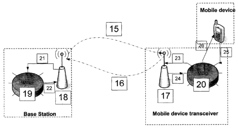
With reference to Fig. 5, the steps of an embodiment of the present
invention will be detailed. In the microcontroller unit 19 is a zone definer
for
defining a critical zone to be one of within or outside a range. In the
present
example, the critical zone is defined as being within the range of the base
station.
- 6 -
CA 02610048 2007-11-28
WO 2006/128308
PCT/CA2006/000923
The add-on transceiver microcontroller unit 20 wakes up regularly, at
predetermined time intervals, such as one minute, to start the ping
communication. The microcontroller unit 20 sends 23 its own unique ID to the
RF
part of the add-on transceiver 17 (including both a transmitter and a
receiver).
The microcontroller unit 20 starts a timeout timer, the timeout timer having a
duration of, for example, 50 millisecond. The signal is sent via wireless
communication 15. The timeout timer, or a separate location timer, can be used
to periodically trigger the transmission of a location message to the base
station.
In the case where the communications device is within the reception range
of the base station (and the base station is within the transmission range of
the
communications device), the signal is received by the RF part of the base
station
transceiver 18 (including both a transmitter and a receiver). The signal is
then
converted into a digital wired signal 21 by the transceiver 18. The signal is
sent to
the microcontroller of the base station 19. The signal is then encrypted using
a
known encryption key by the microcontroller 19. The signal is sent 22 to the
RF
part of the base station. The signal is sent via wireless communication 16.
The signal is received by the RF part of the add-on transceiver 17. The
signal is sent 24 to the microcontroller 20 before expiry of the timeout
timer. The
microcontroller 20 correlates the signal to determine if the signal is from a
known
base station or just a signal picked up in error.
A location determiner inside the microcontroller 20 defines the location of
the communications device to be within the range of the base station if the
signal
is from a known base station. If the signal is recognized to be from a known
base
station, a state modifier inside the microcontroller 20 triggers a shut-down
or
power on command (depending on the type of zone) and this is sent to the
communications device 26. An acknowledge is received by the microcontroller 20
from the communication device 25 confirming that the command was executed
and that the current state of the device is on or off. If the status is
appropriate, the
microcontroller 20 goes back to its sleep mode until the next time interval
for
verification is reached. In one embodiment, the state modifier will only
trigger the
power on or turn off command when a change of status of the communications
device has been detected.
- 7 -
CA 02610048 2007-11-28
WO 2006/128308
PCT/CA2006/000923
If the signal is not recognized to be from a known base station, the timeout
timer of the add-on microcontroller 20 expires in due course. The
microcontroller
20 tries to ping the base station once more by repeating the previous steps.
In
the case where the communications device is not within the reception range of
the base station (and the base station is not within the transmission range of
the
communications device), the signal is never responded to by the base station.
The timeout timer of the add-on microcontroller 20 expires in due course. The
microcontroller 20 tries to ping the base station once more by repeating the
previous steps. If the timeout timer expires a second time, the
microcontroller 20
sends a status request to the communications device. The communications
device responds with its status, namely on or off.
The microcontroller 20 verifies whether the status is appropriate depending
on the type of zone. If the status is appropriate, the microcontroller 20 goes
back
to its sleep mode until the next time interval for verification is reached. If
the
status is inappropriate, namely the device has transitioned from within to
outside
a zone or the opposite, a shut-down or power on command (depending on the
type of zone) is sent to the communications device 26. An acknowledgement is
received by the microcontroller 20 from the communications device 25
confirming
that the command was executed and that the current state of the device is on
or
off. If the status is appropriate, the microcontroller 20 goes back to its
sleep mode
until the next time interval for verification is reached.
In one embodiment of the present invention, the microcontroller 20 of the
communications device includes a call forward module, which automatically
forwards incoming communication calls to a separate number prior to turning
the
device off.
As will be readily understood, the above method could be modified
substantially without departing from the invention. Indeed, the instigator of
the
verification could be the base station instead of the cellular phone. The time
intervals could be chosen to be any other time intervals. The acknowledgement
by the phone of its updated status is not required. Indeed, the
acknowledgement
confirms that the phone reacted to the command in the appropriate way,
however, one could simply assume that the phone will receive and treat the
- 8 -
CA 02610048 2007-11-28
WO 2006/128308
PCT/CA2006/000923
command in the right way, without requiring an acknowledgement. In an
alternative embodiment, the transceiver of the mobile device may only ping the
base station once, even if no response is received. In this case, the default
would
be to assume that the mobile device is out of the range of the base station if
the
base station does not respond and the process would simply be halted until the
next time for verification is reached. The transceiver of the mobile device
does
not have to first check the current status of the device prior to instructing
it using
the zone. Indeed, the command to power on or shut down the device could be
sent even though the device would already be in power on or shut down mode.
And so on.
At all times, it is possible for a user to manually bypass the status of his
phone (powered on or shut down) by using the standard keys provided on the
phone.
A plurality of phones could be controlled by one base station. Each phone
could also relate and communicate with a plurality of base stations to define
a
multitude of zones.
Most cellular phone uses AT commands. Those commands are used for
setting up things or command action. The commands used are often proprietary
to one brand of devices but could be of the type below:
AT + CCFC = params (for call forwarding)
AT + CFUN = 0,0 (to shut down the wireless communication feature of the
device)
AT + CFUN = 0,1 (to power on the wireless communication feature of the
device).
The preferred embodiment for the base station and the add-on is a
Microchip PIC18F4520 QFN 44 pins connected to a Nordic 2.4 GHz digital
transceiver model nRF2401. Fig. 6 shows a preferred circuit diagram for the
microcontroller and the transceiver, Fig. 7 shows the microcontroller
Microchip
PIC18F4520 QFN 44 pins itself and Fig. 8 shows the transceiver Nordic nRF2401
itself.
- 9 -
CA 02610048 2007-11-28
WO 2006/128308
PCT/CA2006/000923
The embodiments of the invention described above are intended to be
exemplary only. The scope of the invention is therefore intended to be limited
solely by the scope of the appended claims.
- 10-