Note: Descriptions are shown in the official language in which they were submitted.
CA 02610176 2014-03-05
30764-3
- 1 -
Device For Satinizing And Embossing Packaging Foils
The present invention refers to a device for satinizing and
embossing packaging foils that has at least three embossing
rolls.
However, it is also possible to use a device having two
embossing rolls.
Devices of this kind are known from EP-A-1 372 946 to the
applicant of the present invention. This European patent
application is a further development of the device according
to US-B-6 715 411 to the same applicant. The two devices
defined therein have in common that the paper web first
passes through a first roll pair and then through a second
roll pair, the application of three rolls allowing to reduce
the contact pressure and to achieve an improved breaking of
the paper component of the foil.
The surface structures of the embossing rolls, i.e. the
arrangements of teeth, circular ridges, or longitudinal
ridges on the known rolls, break the paper symmetrically,
whereby, as compared to the previously known state of the
art, a more homogenous breaking of the fibers in two
directions and finer embossing patterns can be achieved,
wrinkling in the logo area is avoided, a reduced tendency to
tubing and curling is observed, and good fold
characteristics, or so-called dead fold characteristics, can
be achieved.
Recently, however, further problems have been encountered
with foils on a paper substrate. Some of these problem areas
resulting from the various new paper properties are
indicated below:
Mk 02610176 2007-11-13
(F:\TT\SE\A0MELDUN\27552E.DOC Prt: 15.10.2007 SE)
- 2 -
a) An influential factor that is difficult to control is
the inconsistency regarding the composition of the foil, or
inner liner, as it is called in the cigarette industry, the
difficulties residing in the fact that the diversity of
commercially available inner liner papers is continuously
increasing without any standardization tendencies being
apparent. This means that depending on the region or the
requirements from the marketing sector, papers having a
specific surface weight of 30 g/m2 to 80 g/m2 are being used
which are metallized, aluminum coated or surface-treated,
e.g. by printing, to obtain a metal-like surface. In the
application of so-called shadow embossings, see e.g. US-B-
7 036 347 to the applicant of the present invention, very
fine structures are produced which have to be embossed with
constant quality independently of the material.
b) The mechanical properties of the foils are largely
determined by the pulp fibers that are used, by their
morphological properties, and the way they are processed.
Outwardly similar foils may therefore strongly differ in
their mechanical behavior. For these reasons, it is
desirable to achieve good results with inner liners of poor
quality.
c) For the industrial embossing of the different foils it
is therefore desirable to become more independent from their
large sensitivity range.
d) Another, economical challenge consists in embossing
foils of different compositions in such a manner that they
hardly differ from each other optically any more when
contemplating similarly embossed marks. In the current state
of the art, depending on the composition of the foil, the
same embossing patterns, both in logos and in shadow
CA 02610176 2014-03-05
30764-3
- 3 -
embossings, may look very different to the eye.
On the background of this prior art, it is an object of some
embodiments to provide a device for satinizing and embossing
foils by means of which the fibers of the paper substrate of the
foil are broken even more effectively in order to yield an
improved overall esthetical impression after the embossing
procedure that is substantially independent from the composition
of the paper substrate of the foil and to allow a perfect
embossing of fine structures.
According to one aspect of the present invention, there is
provided device for satinizing and embossing packaging foils,
comprising a first, a second, and a third embossing roll, the
first embossing roll being in rolling contact with each of the
second or third embossing rolls and the packaging foil being
configured for being passed under pressure between the first and
the second and between the first and the third embossing rolls in
order to produce a satin-finish and a pattern, the first
embossing roll having a tooth array arranged in a basic grid and
composed of homogenously arranged individual teeth, and the other
two embossing rolls having a surface structure that differs from
that of the first embossing roll, wherein at least one of the
other two embossing rolls has a surface structure with structural
elements that are arranged individually or in groups but not in
the same basic grid as on the first embossing roll, each
structural element consisting of individual teeth or of a
continuously formed ridge or of a combination of these two
configurations, and at least one of the teeth and ridges having a
mutual spacing that differs from the basic grid, and the
structural elements being arranged circularly, longitudinally, or
helically on at least one of the second and third embossing roll.
CA 02610176 2014-03-05
30764-3
- 3a -
According to another aspect of the present invention, there is
provided device for satinizing and embossing packaging foils,
comprising a first and a second embossing roll, the two embossing
rolls being in rolling contact with one another and the packaging
foil being configured for being passed under pressure between the
first and the second embossing rolls in order to produce a satin-
finish and a pattern, the first embossing roll having a tooth
array arranged in a basic grid and composed of homogenously
arranged individual teeth, and the other embossing roll having a
surface structure that differs from that of the first embossing
roll, wherein the second embossing roll has a surface structure
with structural elements that are arranged individually or in
groups but not in the same basic grid as on the first embossing
roll, each structural element consisting of individual teeth or
of a continuously formed ridge or of a combination of these two
configurations, and at least one of the teeth and ridges having a
mutual spacing that differs from the basic grid, and the
structural elements being arranged circularly, longitudinally, or
helically on the second embossing roll.
According to yet another aspect of the present invention, there
is provided method for satinizing and embossing packaging foils
by means of a device as described herein, wherein the packaging
foil that consists of metallized or surface-treated or aluminum
coated paper passes through a first embossing roll pair and
subsequently through a second embossing roll pair, the metallic
or surface-treated layer of the foil facing the first embossing
roll, and at least one embossing roll pair having a non-
homogenous grid pattern of the surface structure that differs
from the basic grid of the first embossing roll in order to
achieve an effective breaking of the paper fibers.
CA 02610176 2014-03-05
30764-3
- 3b -
According to still another aspect of the present invention, there
is provided method for satinizing and embossing packaging foils
by means of a device as described herein, wherein the packaging
foil that consists of metallized or surface-treated or aluminum
coated paper passes through the embossing roll pair, the metallic
layer of the foil facing the first embossing roll, and the
embossing roll pair having a non-homogenous grid pattern of the
surface structure that differs from the basic grid of the first
embossing roll in order to achieve an effective breaking of the
paper fibers.
The invention will be explained in more detail hereinafter with
reference to drawings of exemplary embodiments.
Fig. 1 shows, schematically and in a perspective view, a
device with an embossing roll having a homogenous
arrangement of teeth that cooperates with two
additional embossing rolls,
Figures 2 to 5 each show respective structures of the two
additional embossing rolls in a detail
enlargement,
Fig. 6 shows an embodiment variant of the structures of the
additional embossing rolls,
Figures 7 and 8 show further embodiment variants of the
structures of the additional embossing
rolls,
Fig. 9 schematically shows a cross-section of the three
unsynchronized embossing rolls,
CA 02610176 2007-11-13
(F:\TT\SE\ANMELDUN\27552E.DOC Prt: 15.10.2007 SE)
- 4 -
Fig. 10 schematically shows a cross-section of the three
synchronized embossing rolls,
Fig. 11 shows a detail enlargement of teeth of the first
embossing roll that are provided with macro- and
microstructures,
Fig. 12 shows different possible microstructures of the
tooth surface of Fig. 11 on a further enlarged
scale,
Fig. 13 shows a variant of Fig. 11 where macrostructures
and microstructures are provided on the teeth,
Fig. 14 shows a second embodiment of the invention having
two embossing rolls.
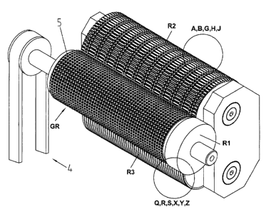
In the schematic illustration of Fig. 1, three embossing
rolls R1, R3, and R2 are shown, embossing roll R1 being
driven by a drive 4. Embossing roll R1 is known per se and
has been disclosed in different patent specifications as
well as in the references cited in the introduction. Driven
embossing roll R1 has a surface structure formed of
individual teeth 5 that are arranged in a both axially and
circularly homogenous grid pattern and by which the satin
finish is achieved. This surface structure is called the
basic grid GR. The teeth of the latter may be pyramidal with
different cross-sections, frustopyramidal, or conical in
shape. In the case of pyramidal teeth, the latter have a
cross-section in the shape of a tetragonal parallelogram.
The two additional embossing rolls R2 and R3 may be driven
via foil 9 and by means of suitable surface structures by
first embossing roll R1, see Fig. 9, or by means of a
CA 02610176 2007-11-13
(E:\TT\SE\ANMELDUN\27552E.DOC Prt: 15.10.2007 SE)
- 5 -
synchronizing gear 6, 7, and 8 of a type known in the art
per se, see Fig. 10. Generally, foil 9 is passed through the
embossing rolls in such a manner that the metallized or
treated surface is facing first embossing roll Rl.
However, it is also possible to drive embossing roll 2 or 3
rather than embossing roll 1 and to let the other embossing
rolls run freely. Instead of a synchronization by means of
gearwheels, a synchronization by means of belts or
electronic means is also possible.
In the manufacture of paper, the so-called flocculation is a
key process that consists in that fibrous suspensions have a
natural tendency to flaking. The latter increases with the
fiber concentration, thereby resulting in an increasing
stock consistency. The dense fiber flocculation observed in
may inner liners results confers the paper a relatively high
rigidity. However, the flakes are distributed over the paper
surface very irregularly, and a homogenous, fine sieve
structure cannot be achieved.
Studies have shown that with a uniform tooth array, the foil
tends to be shortened in the traveling direction, i.e. in
the longitudinal direction, and to be slightly widened in
the transversal direction during the embossing operation.
This effect may be explained by the fact that the pulp
fibers are mainly aligned in the longitudinal direction. As
the fibers are crushed, they naturally increase in width and
only little in length.
To counteract this tendency, according to the prior art, the
surface of each embossing roll was provided with elevations
and impressions of the same kind, i.e. with the basic grid,
e.g. with pyramidal teeth of different cross-sections such
as tetragonal parallelograms, truncated pyramids, or conical
CA 02610176 2007-11-13
(F:\TT\SE\ANMELDUN\27552E.DOC Prt: 15.10.2007 SE)
- 6 -
teeth, thereby allowing an interaction with other embossing
rolls involved in the embossing process.
Asymmetrical structural elements in the basic grids composed
of identical teeth were avoided in order to counteract a
distortion of the embossing pattern. Recently, different
alternatives have been examined to cope with the
requirements brought about by the different paper types and
qualities.
Tests have now shown that by using embossing rolls provided
with different structural elements such as toothed crowns,
tooth rows that are circularly, helically, or longitudinally
arranged along the embossing roll and whose grid is not the
same as the basic grid GR of the first embossing roll, a
very important improvement of the breaking action,
respectively of the neutralization of the substructures
created in the paper substrate by flocculation could be
achieved. This may be explained by the fact that structures
of the roll surface which do not have the same basic grid GR
are more suitable for eliminating accidentally formed
flakes. This applies both to the three-roll and to the two-
roll arrangement.
With the use of the rolls described below, not only a better
breaking and neutralization of the paper substrate with
regard to wrinkling, tubing and curling is achieved, but
particularly also an esthetically significantly improved
foil surface that confers the latter a precious appearance.
Ultimately, such a foil surface allows a finer and more
precise embossing of very fine structures which serve e.g.
for producing authentication and identification features.
As seen in Fig. 9 or 10, foil 9 first passes through roll
pair R1 and R2 and subsequently through roll pair R1 and R3.
CA 02610176 2007-11-13
(P:\TINSE\ANMELDUN\27552E.DOC Prt: 15.10.2007 SE)
- 7 -
It follows that the foil first passes through the
arrangement of different structures of one of the roll pairs
and is subsequently treated in another manner, i.e.
inhomogenously, by the surface structure of the second roll
pair assembly, thereby resulting in an altogether
inhomogeneous treatment of the foil that produces surprising
results.
In Fig. 1, as already mentioned in the introduction,
embossing roll R1 is provided with homogenously arranged
individual teeth 5 defining the basic grid GR. The latter
may be pyramidal or conical teeth having a flattening of at
least 2 %, preferably at least 5 %, the cross-section of the
pyramidal teeth having the shape of a tetragonal
parallelogram.
Furthermore, in Fig. 1, the surface structures of embossing
rolls R2 and R3 are symbolized by letters A to J and Q to Z,
respectively. Upon comparison of Fig. 1 to Fig. 2 it is
apparent that the designation R2A denotes surface structure
A of embossing roll R2, and R3Q the surface structure Q
provided on embossing roll R3, etc.
In Fig. 2, possible surface structures of embossing rolls R2
and R3 are depicted. Surface structure A of the roll surface
of R2 according to Fig. 2 is defined by longitudinal ridges
10 that are interrupted by individual structural elements in
the form of tooth rows 11, tooth row 11 being composed of
individual teeth 5 and the teeth in the present example
having a frustopyramidal shape. Therefore, instead of
uniform longitudinal ridges as they are known from the prior
art, the surface of R2 consists of longitudinal ridges that
are interrupted by circular tooth rows while the grid of
these structural elements is not the same as basic grid GR.
CA 02610176 2007-11-13
(F:\TT\SE\ANMELEEN\27552E.DOC Prt: 15.10.2007 SE)
- 8 -
Here, the structure Q of third embossing roll R3 consists of
uniformly arranged circular ridges 12 in a manner known per
se in embossing rolls of the prior art.
In cross-section, the longitudinally, transversally, or
helically arranged structural elements are outwardly tapered
and flattened, the dimensions of the structural elements and
of the grooves therebetween corresponding to the dimensions
of teeth 5 of the first, driven embossing roll R1, and all
teeth engaging in the grooves between the ridges.
In Fig. 3 it is shown that surface structure B of embossing
roll R2 comprises the interrupted longitudinal ridges 10 as
well as double tooth rows 13, while it is understood that
three or more tooth rows interrupting longitudinal ridges 10
may be provided. Embossing roll R3 has the same surface
structure Q as in Fig. 2.
In Fig. 4 it is shown that embossing roll R2 has the same
surface structure A as in Fig. 2 while embossing roll R3 has
a surface structure R in which circular ridges 14 are
interrupted by longitudinally arranged tooth rows 15, the
latter being composed of individual teeth 5.
In the illustration of Fig. 5, embossing roll R2 has the
same surface structure B as in Fig. 3 while embossing roll
R3 has a surface structure S where circular ridges 14 are
interrupted by double longitudinal rows 16, the latter again
being composed of individual teeth 5.
The description of Figures 1 to 5 already shows that a large
diversity of variations is conceivable. Thus, it is of
course possible not only to provide structural elements in
the form of single or double rows of teeth, but also triple
CA 02610176 2007-11-13
(F:\TT\SE\ANMELDUN\27552E.DOC Prt: 15.10.2007 SE)
- 9 -
or multiple rows of individual teeth between which
longitudinal or circular ridges are arranged.
Furthermore it will be appreciated that both the dimensions
of the individual teeth and the distances between the tooth
rows may vary, as well as the dimensions and distances of
the longitudinal or circular ridges, provided that they are
dimensioned and arranged so as to always interlock with or
roll off on the grid of teeth of embossing roll Rl. It is
understood that any desired combination of the indicated
roll types of both embossing rolls is possible.
Whereas Figs. 1 to 5 illustrate surface structures in which
the structural elements or arranged orthogonally to the
longitudinal axis of the rolls, Figs. 6 and 8 illustrate
surface structures in which the structural elements formed
of individual teeth or of continuous ridges are arranged
helically.
In Fig. 6, a surface structure G is shown for embossing roll
R2 in which structural elements 17 are helically arranged in
the same longitudinal ridges 10 as in Fig. 5, e.g. at an
angle of 450 with respect to the longitudinal axis, these
elements being again composed of tooth rows comprising
individual teeth 5.
Mating roll R3 has a surface structure X whose configuration
is the mirror image of structure G while structural elements
18 formed of two rows of teeth 5 and arranged at an angle of
e.g. 45 with respect to the longitudinal axis of the
embossing roll are provided, however. As shown in Figs. 3,
4, and 5, embossing roll R3 with surface structure X is also
provided with rings 12 that are interrupted by structural
elements 18.
CA 02610176 2007-11-13
(F:\TT\SE\ANMELDUN\27552E.DOC Prt: 15.10.2007 SE)
- 10 -
In Fig. 7, a surface structure H is illustrated for
embossing rolls R2 whose structural elements are not
composed of rows of individual teeth but of circular ridges
19, the distances between the individual ridges being
variable, and no longitudinal ridges being provided.
Embossing roll R3 has the surface structure Y that is
composed of longitudinal ridges 20. Here also, the
cooperation of embossing rolls R2 and R3 results in a non-
homogenous breaking of the paper fibers.
Embossing rolls according to Fig. 8 can be regarded as being
analogous to the embossing rolls according to Fig. 6 in that
helically arranged ridges 21 are provided as the structural
elements, however without intermediate longitudinal or
transversal ridges. The distances between the individual
ridges may again be variable. In this example, ridges 22 of
embossing roll R3 forming the surface structure Z are
helically arranged next to one another. Here also, the
interaction of the two embossing rolls R2 and R3 results in
a non-homogenous embossing action and thus in a maximum
breaking action of the paper fibers.
Based on these exemplary embodiments, a very large number of
variations are possible, both with regard to the distances
between the individual paths and to the angle of the
circumferential paths. Combinations of the depicted types
are also possible, i.e. individual circular, longitudinal or
helical paths may be composed of individual teeth.
Furthermore it is apparent to one skilled in the art that
the teeth need not necessarily be rectangular or square
pyramids that are flattened at their tips but may also be
conical, preferably flattened teeth.
For certain paper types it is sufficient to use only a two-
roll device according to Figure 14. Correspondingly, all the
CA 02610176 2007-11-13
(E:\TT\SE\ANMELDUN\27552E.DOC Prt: 15.10.2007 SE)
- 11 -
previously described surface structures also apply to the
two-roll device, driven embossing roll R31 having a basic
grid GR1 that is analogous to basic grid GR. As an
embodiment variant, teeth 35 have a rhombic cross-section
where the sides can be arranged at a desired angle with
respect to the longitudinal axis, e.g. turned by 450. In
this manner, a good synchronization of the two rolls is
achieved.
The second roll R2 is always provided with a non-homogenous
surface structure, e.g. according to A, B, G, H, J; R, S, X.
If the first embossing roll has a tooth array as that of R1,
the second roll may be driven either through the shape of
the teeth and ridges via the foil, or via synchronizing
means.
In the represented form, the described and illustrated
embossing rolls are suitable for an optimal satinizing of
packaging foils, more particularly of cigarette papers. If
logos are desired, they are preferably provided as known
from the prior art on embossing roll R1 provided with basic
grid GR or GR1. This is accomplished by removing teeth at
the location where the logo is to appear, so that the
metallized or treated surface of the foil that comes to lie
on this location will not be altered during its passage and
remains glossy.
As mentioned in the introduction already, a particularly
fine surface of the foil is obtained with the treatment of
to the invention so that in addition to logos,
authentication and identification features that are
particularly fraud resistant and have very fine structures
may be embossed. Furthermore, this surface structure is also
particularly suitable for so-called shadow embossing, which
will be described below.
CA 02610176 2007-11-13
(P:\TT\SE\ANMELDUN\27552E.DOC Pit: 15.10.2007 SE)
- 12 -
Authentication and identification features and shadow
embossings may e.g. be produced according to US-B-7 036 347
to the applicant of the present invention or by means of
embossing rolls as disclosed in EP-A-1 437 213 to the same
applicant.
In Figures 11 to 13, a surface treatment of the individual
teeth and of the tooth bottom of driven embossing roll R1
that is called "macrostructure" and "microstructure" in EP-
A-1 437 213 is illustrated by way of example.
In Figure 11, six teeth 5S1 to 5S6 are depicted whose
microstructures are shown hatched. The teeth are
frustopyramidal with a rectangular horizontal projection,
the lateral edges extending in parallel respectively
perpendicularly to the longitudinal axis of the roll, and
the pyramids being flattened.
Tooth 5S1 has a microstructure 20 on the flattened portion
of the tooth as well as a microstructure 21 on one or both
transversal sides of the tooth, and tooth 5S4 has the same
surface structure 20 and a microstructure 22 on one or both
longitudinal side(s) of the tooth. Tooth bottom ZG may be
provided with a microstructure 23 along the longitudinal
side of the teeth or with a microstructure 24 extending over
certain lengths or with a microstructure 25 extending
transversally thereto.
Tooth 5S2 has a microstructure 26 that extends over the
entire side on one or both of its longitudinal sides, and
tooth 5S3 has a microstructure 27 that extends over the
entire surface of its flattened portion. Teeth 5S5 only have
narrow microstructures 28 extending across the height of
their longitudinal sides while tooth 5S6 is unchanged. In
CA 02610176 2007-11-13
(F:\TT\SE\ANMELDUN\27552E.DOC Prt: 15.10.2007 SE)
- 13 -
this manner, it is understood that a large variety of
microstructures can be applied, thereby creating a
correspondingly large variety of patterns on the foil.
In Figures 12A to 12D, some examples of possible straight or
curved microstructures on top and on the sides of the teeth
are indicated at a larger magnification. In Figure 12A, a
cross-section of a positive grid structure is illustrated,
the individual ridges 30 being arranged at intervals of some
m. This structure may be used for any one of
microstructures 20, 21, 28, or 29 but may also be applied to
the tooth bottom, e.g. for microstructures 23, 24, or 25.
In Figure 12B, a cross-section of a negative grid structure
is schematically indicated where recesses 31 are again
arranged at intervals of some 100 nm to some m.
In Figure 120, a possible positive microstructure formed of
grid-like, curved ridges 32 is schematically indicated in a
perspective view.
In Figure 12D, a possible negative microstructure formed of
grid-like, curved grooves 33 is schematically indicated in a
perspective view. This structure is e.g. appropriate for use
in microstructure 24 or 25.
It becomes apparent from these few examples that a very
large range of variation both of the microstructures,
respectively of the arrangement of these microstructures on
the individual teeth and on the tooth bottom or only on the
tooth bottom alone, and of the kind of the microstructures
themselves is possible. This depends on the current state of
the art with regard to the production of such structures,
the production of microstructures being also applied
particularly in the manufacture of electronic chips and
CA 02610176 2007-11-13
(P:\TT\SE\ANMELDUN\27552E.DOC Prt: 15.10.2007 SE)
- 14 -
known from this field. In such fine microstructures, the
application of suitable methods such as lacquer or etching
techniques plays an important role. When irradiated, such a
microstructure produces a diffraction of the light.
The teeth of Figure 13 are provided both with
macrostructures and microstructures. In this regard, the
term "macrostructure" is meant to designate a modification
of the tooth geometry which in the embossing procedure
produces marks whose appearance varies according to the
viewing angle of the observer and/or the kind and/or the
position of the lighting source. These geometrically
modified teeth emboss the metallic surface of the foil to a
greater or lesser extent. A microstructure may be
superimposed on this macrostructure in order to provide the
shadow embossing with special effects.
Figure 13 illustrates three geometrically unmodified teeth
5S1, 5S4, and 5S6, however with microstructures as in Figure
11, as well as geometrically modified teeth 5M1, 5M2, and
5M3 where the "M" stands for macrostructure. Tooth 5M1
exhibits a greater amount of flattening than a regular tooth
such as 5S1, the flattened portion being provided with a
microstructure 20.
Tooth 5M2 only has a larger amount of flattening and is
otherwise unmodified, whereas tooth 5M3 is cut in half in
its width. Of course, teeth 5M2 and 5M3 may be provided with
microstructures as well. Again, in the example according to
Figure 13, the tooth bottom may be machined and may have the
same microstructure 23 as in Figure 11 and a microstructure
25.
An even greater variety of possible modifications of teeth
results from the illustration of Figure 13, thereby
CA 02610176 2007-11-13
(F:\TT\SE\A0MELDUN\27552E.DOC Prt: 15.10.2007 SE)
- 15 -
providing a very large variety of embossing patterns.
Alternatively, only the structures on the tooth bottom may
be used for embossing alone.
In this regard it should be mentioned that all teeth having
macrostructures and microstructures are intended to modify
the metallized or treated surface of the foil, in contrast
to the tooth gaps at the location of the logos, which do not
modify the surface of the foil.
It follows from the description of the surface structures of
the rolls and of the macrostructures and microstructures of
the teeth that the embossing rolls are made of metal.
- - - - -