Language selection

Search

Patent 2610279 Summary

Third-party information liability

Some of the information on this Web page has been provided by external sources. The Government of Canada is not responsible for the accuracy, reliability or currency of the information supplied by external sources. Users wishing to rely upon this information should consult directly with the source of the information. Content provided by external sources is not subject to official languages, privacy and accessibility requirements.

Claims and Abstract availability

Any discrepancies in the text and image of the Claims and Abstract are due to differing posting times. Text of the Claims and Abstract are posted:

  • At the time the application is open to public inspection;
  • At the time of issue of the patent (grant).
(12) Patent: (11) CA 2610279
(54) English Title: TOOL FASTENING DEVICE FOR A WEDGE DRIVE
(54) French Title: DISPOSITIF DE FIXATION D'OUTIL POUR MECANISME A CLAVETTE
Status: Deemed expired
Bibliographic Data
(51) International Patent Classification (IPC):
  • B21D 28/32 (2006.01)
(72) Inventors :
  • WEIGELT, ELKE (Germany)
(73) Owners :
  • WEIGELT, ELKE (Germany)
(71) Applicants :
  • WEIGELT, ELKE (Germany)
(74) Agent: RIDOUT & MAYBEE LLP
(74) Associate agent:
(45) Issued: 2011-01-25
(86) PCT Filing Date: 2006-06-22
(87) Open to Public Inspection: 2006-12-28
Examination requested: 2007-11-29
Availability of licence: N/A
(25) Language of filing: English

Patent Cooperation Treaty (PCT): Yes
(86) PCT Filing Number: PCT/EP2006/005993
(87) International Publication Number: WO2006/136404
(85) National Entry: 2007-11-29

(30) Application Priority Data:
Application No. Country/Territory Date
10 2005 029 140.6 Germany 2005-06-23

Abstracts

English Abstract


The invention relates to an upper part V-belt drive (1) with a tool fastening
device (10, 200, 300, 400) having at least one lateral surface (19), which can
be provided with a tool, and the V-belt drive (1) has a slider element (2,
420) and a driver element (3, 430). According to the invention, the tool
fastening device (10, 200, 300, 400) is fastened in a manner that enables it
to be removed downward with regard to the upper part V-belt drive (1) when in
the working position thereof. In a tool fastening device (10, 200, 300, 400)
for a V-belt drive (1) with a slider element (2, 420) and with a driver
element (3, 430), the tool fastening device (10, 200, 300, 400) comprises at
least one lateral surface (19), which can be provided with a tool, and the
tool fastening device (10, 200, 300, 400) has at least one connecting device
(11, 14, 22, 213, 214, 215, 219, 313, 314, 316, 317, 318, 319, 408, 409, 410,
411, 414) for positively and/or non-positively connecting with the slider and
driver element.


French Abstract

L'invention concerne un mécanisme à clavette à partie supérieure (1) comprenant un dispositif de fixation d'outil (10, 200, 300, 400) qui présente au moins une face latérale (19) pouvant être munie d'un outil. Ledit mécanisme à clavette (1) présente un élément coulissant (2, 420) et un élément d'attaque (3, 430). Le dispositif de fixation d'outil (10, 200, 300, 400) est fixé de manière démontable dans sa position de travail, en direction du bas par rapport au mécanisme à clavette à partie supérieure (1). Dans un dispositif de fixation d'outil (10, 200, 300, 400) pour mécanisme à clavette (1) comprenant un élément coulissant (2, 420) et un élément d'attaque (3, 430), le dispositif de fixation d'outil (10, 200, 300, 400) comporte au moins une surface latérale (19) pouvant être munie d'un outil et au moins un dispositif d'assemblage (11, 14, 22, 213, 214, 215, 219, 313, 314, 316, 317, 318, 319, 408, 409, 410, 411, 414) pour un assemblage par liaison de forme et/ou de force avec l'élément coulissant et l'élément d'attaque.

Claims

Note: Claims are shown in the official language in which they were submitted.


CLAIMS

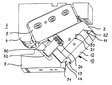
1. An upper part cotter key (1) with a tool fastening device (10, 200,
300, 400) having at least one lateral surface (19) which can be provided
with a tool, wherein the cotter key (1) has a slider element (2, 420) and a
driver element (3, 430),
characterized in that
the tool fastening device (10, 200, 300, 400) is fastened
dismantleably downwardly in relation to the upper part cotter key (1) in the
working position thereof.


2. The upper part cotter key (1) as set forth in claim 1 characterized
in that the tool fastening device (10, 200, 300, 400) can be dismantled at a
angle perpendicularly to the working direction of the cotter key in the
direction of the opened cotter key.


3. The upper part cotter key (1) as set forth in claim 1 or claim 2
characterized in that the cotter key (1) has at least one portion which faces
towards the tool fastening device (10, 200, 300, 400) and which to carry
return traction forces has at least one connecting device (11, 14, 22, 213,
214, 215, 219, 313, 314, 316, 317, 318, 319, 408, 409, 410, 411, 414) for
positively lockingly and/or force-lockingly connecting to the tool fastening
device (10, 200, 300, 400).


4. The upper part cotter key (1) as set forth in one of claims 1
through 3 characterized in that on the side towards which it is removable
from the cotter key the tool fastening device (10, 200, 300, 400) can be
fixed or is fixed to the cotter key by way of at least one fastening means, in

particular screws.


5. The upper part cotter key (1) as set forth in claims 1 through 4
characterized in that the tool fastening device (10, 200, 300, 400) can be
provided or is provided with at least one guide prism (14, 414) and/or at
least one prismatic recess (213) and/or at least one prism portion (320,
321) for support on a driver prism (31, 431).


22


6. The upper part cotter key (1) as set forth in claim 5 characterized
in that at least one guide prism is integral or adapted to be connectable to
the main body of the tool fastening device.


7. The upper part cotter key (1) as set forth in claim 5 or claim 6
characterized in that the prismatic recess (213) is provided block-like in the

form of an element provided with one or more prismatic sliding surfaces
adapted to the driver element (3) and/or is provided with sliding plates
(214).


8. The upper part cotter key (1) as set forth in one of claims 1
through 7 characterized in that to carry relatively high mass acceleration
forces there is provided at least one lateral holding bar element (50, 51)
which extends beyond the region of the at least one guide prism (14, 414)
and/or the at least one prism portion (320, 321) to the driver element (3,
430).


9. The upper part cotter key (1) as set forth in claim 8 characterized
in that the at least one holding bar element (50, 51) engages laterally at or
under the driver element.


10. The upper part cotter key (1) as set forth in one of claims 1
through 9 characterized in that there are provided one or more holding
noses (52, 53) for the transmission of forces when the slider element is
pulled back, which can be brought into hooking engagement on the driver
element or can be latched therein.


11. The upper part cotter key (1) as set forth in one of claims 1
through 10 characterized in that the tool fastening device (10, 200, 300,
400) is of an L-shaped configuration in one or more parts, wherein a
portion (14, 215, 315, 414) is arranged on the top side and/or the
underside and a portion (12, 211, 311, 412) is arranged on the front side
(21) of the slider element.


23


12. A tool fastening device (10, 200, 300, 400) for a cotter key (1)
having a slider element (2, 420) and a driver element (3, 430), in particular
as set forth in of the preceding claims, wherein the tool fastening device
(10, 200, 300, 400) has at least one lateral surface (19) which can be
provided with a tool,
characterized in that
the tool fastening device (10, 200, 300, 400) has at least one
connecting device (11, 14, 22, 213, 214, 215, 219, 313, 314, 316, 317,
318, 319, 408, 409, 410, 411, 414) for positively lockingly and/or force-
lockingly connecting to the slider and driver elements.


13. The tool fastening device (10, 200, 300, 400) as set forth in
claim 12 characterized in that there is provided at least one surface (20)
which is substantially parallel to the at least one lateral surface (19) which

can be provided with a tool.


14. The tool fastening device (10, 200, 300, 400) as set forth in one
of claims 12 and 13 characterized in that the connecting device for force-
locking connection includes at least one guide prism (14, 414) provided on
a side of the tool fastening device (10) and/or at least one prismatic recess
(213) and/or at least one prism portion (320, 321).


15. The tool fastening device (10, 200, 300, 400) as set forth in
claim 14 characterized in that the at least one guide prism and/or the at
least one prismatic recess is formed integrally with the main body of the
tool fastening device.


16. The tool fastening device (10, 200, 300, 400) as set forth in
claim 14 characterized in that the at least one guide prism (14, 414) is in
the form of a separate element and is or can be connected to the main
body (12, 412) of the tool fastening device (10, 400).


17. The tool fastening device (10, 200, 300, 400) as set forth in
claim 14 or claim 16 characterized in that the at least one guide prism (14,

24


414) and the main body (12, 412) of the tool fastening device (10, 400) are
or can be connected together by fastening means, in particular screws (15).


18. The upper part cotter key (1) as set forth in claim 3 or the tool
fastening device (10, 200, 300, 400) as set forth in one of claims 12
through 17 characterized in that the connecting device (11, 22, 25, 28,
219, 319, 408, 409, 410, 411, 422, 423, 424, 425) for positively locking
connection is a tongue-and-groove connection.


claims

1. An upper part cotter key (1) having a slider element (2, 420), a
slider guide element (4) and a driver element (3, 430), and a tool fastening
device (10, 200, 300, 400) with at least one lateral surface (19) which can
be provided with a tool,
characterized in that
the tool fastening device (10, 200, 300, 400) is fastened
dismantleably downwardly in relation to the upper part cotter key (1) in the
working position thereof.


2. The upper part cotter key (1) as set forth in claim 1 characterized
in that the tool fastening device (10, 200, 300, 400) can be dismantled at
an angle perpendicularly to the working direction of the cotter key in the
direction of the opened cotter key.


3. The upper part cotter key (1) as set forth in claim 1 or claim 2
characterized in that the cotter key (1) has at least one portion which faces
towards the tool fastening device (10, 200, 300, 400) and which to carry
return traction forces has at least one connecting device (11, 14, 22, 213,
214, 215, 219, 313, 314, 316, 317, 318, 319, 408, 409, 410, 411, 414) for
positively lockingly and/or force-lockingly connecting to the tool fastening
device (10, 200, 300, 400).


4. The upper part cotter key (1) as set forth in one of claims 1
through 3 characterized in that on the side towards which it is removable
from the cotter key the tool fastening device (10, 200, 300, 400) can be
fixed or is fixed to the cotter key by way of at least one fastening means, in

particular screws.


5. The upper part cotter key (1) as set forth in claims 1 through 4
characterized in that the tool fastening device (10, 200, 300, 400) can be

22


provided or is provided with at least one guide prism (14, 414) and/or at
least one prismatic recess (213) and/or at least one prism portion (320,
321) for support on a driver prism (31, 431).


6. The upper part cotter key (1) as set forth in claim 5 characterized
in that at least one guide prism is integral or adapted to be connectable to
the main body of the tool fastening device.


7. The upper part cotter key (1) as set forth in claim 5 or claim 6
characterized in that the prismatic recess (213) is provided block-like in the

form of an element provided with one or more prismatic sliding surfaces
adapted to the driver element (3) and/or is provided with sliding plates
(214).


8. The upper part cotter key (1) as set forth in one of claims 1
through 7 characterized in that to carry relatively high mass acceleration
forces there is provided at least one lateral holding bar element (50, 51)
which extends beyond the region of the at least one guide prism (14, 414)
and/or the at least one prism portion (320, 321) to the driver element (3,
430).


9. The upper part cotter key (1) as set forth in claim 8 characterized
in that the at least one holding bar element (50, 51) engages laterally at or
under the driver element.


10. The upper part cotter key (1) as set forth in one of claims 1
through 9 characterized in that there are provided one or more holding
noses (52, 53) for the transmission of forces when the slider element is
pulled back, which can be brought into hooking engagement on the driver
element or can be latched therein.


11. The upper part cotter key (1) as set forth in one of claims 1
through 10 characterized in that the tool fastening device (10, 200, 300,
400) is of an L-shaped configuration in one or more parts, wherein a
portion (14, 215, 315, 414) is arranged on the top side and/or the

23


underside and a portion (12, 211, 311, 412) is arranged on the front side
(21) of the slider element.


12. A tool fastening device (10, 200, 300, 400) for a cotter key (1)
having a slider element (2, 420), a slider guide element (4) and a driver
element (3, 430), in particular as set forth in of the preceding claims,
wherein the tool fastening device (10, 200, 300, 400) has at least one
lateral surface (19) which can be provided with a tool,
characterized in that
the tool fastening device (10, 200, 300, 400) has at least one
connecting device (11, 14, 22, 213, 214, 215, 219, 313, 314, 316, 317,
318, 319, 408, 409, 410, 411, 414) for positively lockingly and/or force-
lockingly connecting to the slider and driver elements.


13. The tool fastening device (10, 200, 300, 400) as set forth in
claim 12 characterized in that there is provided at least one surface (20)
which is substantially parallel to the at least one lateral surface (19) which

can be provided with a tool.


14. The tool fastening device (10, 200, 300, 400) as set forth in one
of claims 12 and 13 characterized in that the connecting device for force-
locking connection includes at least one guide prism (14, 414) provided on
a side of the tool fastening device (10) and/or at least one prismatic recess
(213) and/or at least one prism portion (320, 321).


15. The tool fastening device (10, 200, 300, 400) as set forth in
claim 14 characterized in that the at least one guide prism and/or the at
least one prismatic recess is formed integrally with the main body of the
tool fastening device.


16. The tool fastening device (10, 200, 300, 400) as set forth in
claim 14 characterized in that the at least one guide prism (14, 414) is in
the form of a separate element and is or can be connected to the main
body (12, 412) of the tool fastening device (10, 400).


24


17. The tool fastening device (10, 200, 300, 400) as set forth in
claim 14 or claim 16 characterized in that the at least one guide prism (14,
414) and the main body (12, 412) of the tool fastening device (10, 400) are
or can be connected together by fastening means, in particular screws (15).

18. The upper part cotter key (1) as set forth in claim 3 or the tool
fastening device (10, 200, 300, 400) as set forth in one of claims 12
through 17 characterized in that the connecting device (11, 22, 25, 28,
219, 319, 408, 409, 410, 411, 422, 423, 424, 425) for positively locking
connection is a tongue-and-groove connection.


Description

Note: Descriptions are shown in the official language in which they were submitted.


CA 02610279 2007-11-29

WO 2006/136404 PCT/EP2006/005993
TOOL FASTENING DEVICE FOR A COTTER KEY
The invention concerns an upper part cotter key with a tool fastening
device having at least one lateral surface which can be provided with a tool,
wherein the cotter key has a slider element and a driver element as well as
a tool fastening device for such a cotter key.
A cotter key serves for diverting perpendicularly acting forces of a
press which is used for the production of sheet metal shaped parts, in
particular bodywork parts, into any direction which differs from the vertical.
It is precisely in the production of bodywork parts that the component
geometries which involve undercut configurations and other irregularly
shaped regions mean that the problem arises that they cannot be worked
upon with presses or stamping machines which stamp or press in a
perpendicular direction, so that cotter keys have to be used for that
purpose. Such cotter keys substantially comprise a slider guide element or
guide bed, a driver element or driver wedge and a slider element or
carriage which, by way of the other two elements, transmits the direction of
the pressing force, which is diverted by virtue of the wedge shape. A cotter
key can be arranged in the upper part or in the lower part of a pressing
tool, depending on the respective situation of use. The action thereof is the
same in both cases, namely diverting the forces produce by the pressing
tool, into a direction which differs from the vertical. Usually, the degree of
deflection of the pressing force decides whether the cotter key is arranged
in the lower part or in the upper part of the pressing tool. A diversion of up
to 20 relative to the sole of the pressing tool (horizontal) is generally
provided by cotter keys in the lower part of the pressing tool whereas
greater degrees of deflection are generally effected by the provision of
cotter keys in the upper part of the pressing tool, in favor of an improved
option in terms of removing the bodywork parts from the pressing tool.
The degree of diversion otherwise depends on the working operation which
is to be carried out by the pressing tool, in which respect cotter keys are
used in particular when piercing through openings, cutting partial regions of
1


CA 02610279 2007-11-29

a body to bending over and post-forming undercut portions which cannot
be reached from above or below.
The cotter key is thus only an implementing member of a pressing
tool and serves to drive for example an aperturing punch, a cutting blade or
a shaping jaw in the pressing tool. In that case the cotter key itself usually
does not touch the workpieces. Touching contact or engagement into the
bodywork parts is only effected by the tools which are fixed to the cotter
key (punch, cutting blade, shaping jaw and so forth). The tools are each
appropriately adapted to the inclination of the cotter key in order to permit
the inclinedly oriented machining of the workpiece. By virtue of the
inclinedly oriented structure, this configuration not only gives rise to
manufacturing problems but also increased production costs. That can also
already be seen from the fact that, upon first construction and when
changing the stamping and shaping standardized components, the entire
cotter key has to be dismantled. In many cases however that is possible
only with very great difficulty as the carriage of a driver wedge, by virtue
of
its non-angled external shape, can be only poorly gripped in a vise etc.
Thus fitting machining tools can frequently only be effected at very high
and disproportionate cost.
In order to resolve that problem, tool fastening devices have been
developed, which can be fastened to the slider element of the cotter key so
that the cutting and shaping tools can also be pre-assembled with
machining tools, outside the cotter key and the pressing tool, so that the
operation of changing the tools can be effected quickly and without any
problem.
Such a tool fastening device is disclosed for example in DE 198 60
178 Cl. That tool fastening device which is referred to as a mounting plate
is dismantled by way of fastening screws which are accessible from behind,
which means that it can only be dismantled when the slider element is
displaced upwardly to such an extent that it is accessible from behind, that
is to say from the driver element. The tool fastening device is in the form
of right-angled plate and is arranged on the front side of the slider element
and is supported there downwardly in the direction to the slider guide
2


CA 02610279 2007-11-29

towards the driver element by a step. The tool fastening device also has a
T-shape groove in order to transmit lateral thrusts to the carriage.
Tool fastening devices of that kind enjoy the great advantage that a
change of worn tools and also initial construction in mass production are
considerably facilitated as only a small part of the cotter key, namely the
tool fastening device, needs to be dismantled and removed from the
pressing tool, together with the tool which is to be replaced. That operation
replaces time-consuming and generally highly complicated and expensive
complete dismantling of the entire cotter key, which is usually quite labor-
intensive because of the often severely constricted space circumstances in
a pressing tool and the poor accessibility to the cotter key. It will be noted
however that it is necessary for the tool fastening device to satisfy the high
demands in terms of the tolerance and the forces which occur within a
pressing tool, which inter alia means that the tool fastening device may not
automatically come loose and also laterally occurring thrust forces have to
be absorbed. In addition it should be easily accessibly and reproducibly
accurately assembled and dismantled in order to satisfy the high demands
in terms of accurate positioning of the tools on the cotter key. As cotter
keys generally transmit forces of several hundred tonnes, it is necessary for
the tool fastening device to be securely and firmly carried on the cotter key
in the forward drive movement, that is to say the working procedure,
without flexural deflection. In the return movement the tool fastening
device may also once again neither bend nor be torn away from the cotter
key or be pulled out of its position, even if a tool fastened thereto comes
into hooking engagement in the respective workpiece in the stamping or
shaping operation, and thereby gives rise to a resistance which has to be
overcome in the withdrawal movement. In general return forces of
between 10 and 15 percent of the working force occur, that is to say also
not inconsiderable forces which the tool fastening device must be capable of
withstanding.
In accordance with DE 198 60 178 Cl the mounting plate can be
dismantied by way of fastening screws which are accessible from behind,
wherein the fastening screws are arranged in a horizontal direction, that is
3


CA 02610279 2007-11-29

to say in the working direction of the cotter key. If the mounting plate
were arranged perpendicularly or at least inclinedly relative to the working
direction of the cotter key, the fastening screws would have to be of really
large dimensions, which is generally scarcely possible by virtue of the very
constricted space conditions in a pressing tool.
With a tool fastening device, it was intended to be possible to avoid
burr formation and unnecessary wear of the machining tools, in which
respect the tolerance or reproduction accuracy in terms of positioning of the
tool fastening device should be at a maximum 0.02 mm. Usually such
slight tolerances cannot be achieved with the known tool fastening devices,
not even with that in accordance with DE 198 60 178 Cl.
Therefore the object of the present invention is to provide an upper
part cotter key having a tool fastening device as well as a tool fastening
device for such a cotter key, wherein the aforementioned prerequisites in
regard to reproduction accuracy and tolerances are met, so that an
operator can reduce his manufacturing costs and maintenance expenditure,
wherein the tool fastening device can be easily dismantled from the cotter
key, but upon assembly can be positioned in reproducibly accurate fashion
on the cotter key and fastened thereto, is itself stable and also fits in an
accurate position in operation in relation to the high forces in pressing use.
That object is attained for an upper part cotter key as set forth in
claim 1 in that the tool fastening device is fastened dismantleably
downwardly in relation to the upper part cotter key in the working position
thereof. For a tool fastening device for such a cotter key the object is
attained in that the tool fastening device has at least one connecting device
for connection in positively locking and/or force-locking relationship to the
slider and driver elements. Developments of the invention are defined in
the appendant claims.
That therefore provides an upper part cotter key in which the
possibility of dismantling the tool fastening device downwardly in relation to
the upper part cotter key in the working position thereof affords the great
advantage that good accessibility is afforded, and for example access is not
rendered more difficult due to components such as a stamping or cutting
4


CA 02610279 2007-11-29

die. More difficult accessibility to the fastening means represents a problem
for example in DE 198 60 178 Cl, which however that publication cannot
resolve.
The tool fastening device according to the invention for a cotter key
which is connected both to the slider element and also the driver element in
positively locking and/or force-locking relationship makes it possible for
loss
of positioning during operation of the cotter key to be substantially
prevented. In addition it is possible for the reproduction accuracy in terms
of assembly of the tool fastening device, even after change thereof or after
a change in the tool which is fastened thereon, to be kept in the desired
minimum range of less 0.02 mm. The fact that the tool fastening device is
connected both to the slider element and also the driver element in
positively locking and/or force-locking relationship provides for support and
positioning in at least two directions, whereby the desired positional
accuracy can be achieved. By virtue of the possibility of being able to
dismantle the tool fastening device at an angle substantially perpendicularly
to the working direction of the cotter key in the direction of the opened
cotter key, that affords better accessibility to the one or more fastening
means with which the tool fastening device is fastened to the cotter key. In
the case of the arrangement in accordance with DE 198 60 178 Cl the
slider and the driver first have to be moved very far away from each other
in order to be able to release the mounting plate from the slider and
remove it. The advantageous possibility of being able to remove the tool
fastening device from the cotter key without the driver element and the
slider element being moved completely away from each other in that way
not only permits an easier change but also affords a cost saving as the
operation of changing the tool fastening device can take place more quickly
than is possible in the state of the art.
In the meantime the use of mass-produced standard cotter keys has
become frequently widespread, which signifies for the purchaser that he
can obtain from stock a cotter key which is in a finished worked condition
as standard. Only the fastening bores of the respective and cutting and
shaping tools, that is to say working tools, still have to be individually
5


CA 02610279 2007-11-29

produced by the purchaser. That means therefore that the purchaser has
to completely dismantle the cotter key which is in its finished assembled
condition, in order to specifically work thereon, on his own working
apparatus, for the respective area of use, that is to say in order to be able
to provide on the cotter key in particular suitable fastening bores for the
working tools. In principle he can here admittedly also have recourse to a
mounting plate in accordance with DE 198 60 178 Cl, whereby his
expenditure and complication is certainly already reduced, as that mounting
plate is in the form of a substantially flat plate with mutually parallel
surfaces which can be satisfactorily clamped in a working apparatus. It will
be noted however that that mounting plate cannot be assembled
completely without any problem to any standard cotter key and removed
therefrom. In contrast, the assembly complication and expenditure with
the tool fastening device according to the invention which in comparison
can be very easily fitted to and removed from a cotter key, can be reduced
by 80%. As the tool fastening device according to the invention preferably
has at least one surface substantially parallel to the at least one lateral
surface which can be provided with a working tool, the tool fastening device
according to the invention is very suitable for subsequent working thereof
as by virtue of that configuration it can be substantially more easily gripped
in a vise and so forth of a working apparatus, than a body of a carriage or
slider element, which is of a non-right-angled and generally oddly shaped
configuration. The mounting plate of DE 198 60 178 Cl admittedly already
enjoys the advantage that it can be easily gripped. In comparison
therewith the tool fastening device according to the invention has the great
advantage that the connecting devices thereof, which permit a connection
in positively locking and/or force-locking relationship both to the slider
element and also to the driver element, permit a secure connection to both
elements and thus provide for positioning and holding thereof in relation to
tilting and displacement in various directions.
The provision of the tool fastening device according to the invention
gives considerable cost advantages in regard to manufacture and
maintenance of a cotter key, in which respect for example the overall
6


CA 02610279 2007-11-29

operating and first working costs can be reduced to below 50% over the
manufacturing period which is covered with a cotter key. It is precisely the
operating and first working costs that can otherwise amount to a multiple of
what a cotter key costs overall in regard to purchase thereof.
Preferably the connecting device for making the positively locking
connection is a tongue-and-groove connection. It is possible without any
problem to maintain given positioning even under high pressing forces, by
virtue of the provision of such a tongue-and-groove connection or a
plurality of such connections over the tool fastening device. It is precisely
also in the advance movement that flexural deformation of the tool
fastening device can be avoided in that case as the tongue-and-groove
connection can also be optimally subjected to the effect of increased
pressure forces and, by virtue of the positively locking connection, the tool
fastening device does not deflect in that case but acts as a unit with the
cotter key. In the return movement of the machining tool out of the
workpiece, in which otherwise the machining tool can easily come into
hooking engagement in the workpiece and can thus give rise to a resistance
force in opposition to the withdrawal movement, a positively locking
connection such as a tongue-and-groove connection is also found to be
particularly advantageous as in that case also the tool fastening device
remains stably in its positioning on the cotter key.
Preferably the connecting device for force-locking connection includes
at least one guide prism provided on one side of the tool fastening device
and/or a prismatic recess. Particularly preferably the at least one guide
prism and/or the at least one prismatic recess are formed integrally with
the main body of the tool fastening device. Alternatively the at least one
guide prism is in the form of a separate element and is or can be connected
to the main body of the tool fastening device. Particularly preferably the at
least one guide prism and the main body of the tool fastening device can be
connectable or connected to each other by fastening means, in particular
screws. The provision of a guide prism as the connecting device for
connection in particular to a driver element of the cotter key makes it
advantageously possible to provide support for the tool fastening device on
7


CA 02610279 2007-11-29

the driver element during the movement when working on a workpiece,
that is to say in the advance movement and in the return movement.
The way in which the guide prism is connected to the tool fastening
device, whether it is integral therewith or only joined thereto, can be made
dependent on the respective structural size of the cotter key and the rest of
the construction thereof. The guide prism can be of a block-like nature in
the form of an element provided with a prismatic sliding surface adapted to
the driver element, or it can be of a sliding plate-like configuration.
Alternatively the arrangement may have only one prismatic recess. The
respective configuration can be made dependent on the forces which are to
be carried. An integral configuration of the tool fastening device and the
guide prism is suitable in particular in the case of smaller cotter keys,
whereas making the guide prism in the form of a separate element is
particularly suitable in the case of medium-size and large cotter keys, in
which case also the guide prism may be only in the form of a narrow plate
element or in the form of a compact component, also in each case
depending on the size of the cotter key, that is to say also the forces which
occur when working on a workpiece.
In order not to represent an impediment in terms of the sliding
movement on the driver element, the guide prism can advantageously be
provided with fastening means which are arranged in the longitudinal
direction of the tool fastening device and at least partially sunk in the
guide
prism body. To dismantle the guide prism from the tool fastening device,
the slider element is merely displaced in the workpiece working direction, in
which case then the corresponding fastening means are accessible from
below in the case of the upper part cotter key in the working position
thereof so that dismantling of the tool fastening device can be effected
without any problem. Advantageously in that case the tool fastening device
can be dismantled at an angle perpendicularly to the working direction of
the cotter key, in the direction of the opened cotter key, upon assembly or
dismantling downwardly in relation to the working position of an upper part
cotter key. The approximately perpendicular angle relative to the working
8


CA 02610279 2007-11-29

direction of the cotter key affords easy accessibility upon assembly and
dismantling of the tool fastening device.
Preferably the cotter key designed in accordance with the invention
has at least one portion which faces towards the tool fastening device and
which, for carrying return movement forces, has at least one connecting
device for positively lockingly and/or force-lockingly connecting to the tool
fastening device. Preferably such a connecting device for positively locking
connection is a tongue-and-groove connection which is particularly
preferably provided on the side of the tool fastening device, which is in
opposite relationship to the guide prism. By virtue of that arrangement,
after assembly of the tool fastening device, the part which forms the
positively locking connection is pressed into the desired position and holds
fast therein without an additional fastening being required, for example by
way of screws and so forth. Nonetheless, on the side towards which it is
removable from the cotter key, the tool fastening device can be fixed to the
cotter key by way of at least one fastening means in particular a screw.
That however is not absolutely essential as, after positioning of the tool
fastening device, between the slider and driver elements, it fits in
positively
locking and force-locking relationship.
To carry higher mass acceleration forces, there is preferably provided
at least one lateral holding bar element which extends beyond the region of
the at least one guide prism to the driver element. In a particularly
preferred feature the at least one holding bar element engages laterally at
or under the driver element. It has proven to be advantageous if the at
least one holding bar element extends between the slider element and the
driver element, and in particular is fixed to the slider element. Such a
holding bar element also permits fixing of the tool fastening device in a
lateral direction, that is to say in the direction in which the positively
locking
connection does not afford a hold, at least if it is in the form of a tongue-
and-groove connection which is oriented only in one direction. The
provision of a guide prism admittedly in principle affords the desired hold in
that lateral direction. It will be noted however that it is precisely in
relation
to high mass acceleration forces that occur, that it is advantageous, in
9


CA 02610279 2007-11-29

addition to the stable guide prism, for it also to be fixed laterally to the
slider element, by way of the holding bar elements. The fact that the at
least one holding bar element only fixes the slider element and the driver
element laterally relative to each other further permits a movement in the
longitudinal direction of the driver element, that movement therefore not
being prevented by the holding bar elements. For that purpose the at least
one holding bar element is of a suitable configuration which permits
engagement on the driver element but is not secured thereto. Fastening of
the holding bar element is preferably effected on the slider element as the
slider element slides on the driver element. In principle it is also possible
to
fasten a holding bar element to the driver element and for a holding bar
element to extend over the surface of the slider element and to be caused
to slide along same, in particular at a recess or groove which is provided
there and which can possibly also be extended into the surface of the tool
fastening device.
Preferably there are provided one or more holding noses for the
transmission of forces upon withdrawal of the slider element, which are
hookable to or latchable in the driver element. Latching engagement is
preferably effected in a corresponding groove or recess in the driver
element, in which case movement of the slider element along the driver
element is allowed.
To set forth the invention in greater detail embodiments by way of
example are described more fully hereinafter with reference to the drawings
in which:
Figure 1 shows a perspective view of a cotter key with a tool
fastening device according to the invention,
Figure 2 shows a perspective view from below of the tool fastening
device shown in Figure 1,
Figure 3 shows a perspective view of the tool fastening device of
Figure 1 and Figure 2 without a guide prism,
Figure 4 shows a perspective view of a cotter key with a tool
fastening device according to the invention in a second embodiment with
sliding plates,


CA 02610279 2007-11-29

Figure 5 shows an exploded perspective view from below of the
cotter key with tool fastening device as shown in Figure 4,
Figure 6 shows a perspective view of the cotter key of the Figure 5
with tool fastening device with prismatic recess, without sliding plates,
Figure 7 shows a perspective view of an upper part cotter key with a
third embodiment of a tool fastening device according to the invention,
Figure 8 shows a partly exploded perspective view of a part of the
upper part cotter key shown in Figure 7,
Figure 9 shows a perspective view of the upper part cotter key of
Figure 8 in a direction viewing from below,
Figure 10 shows a perspective view of an upper part cotter key with
a fourth embodiment of a tool fastening device according to the invention,
Figure 11 shows a perspective view of the upper part cotter key of
Figure 10 in a direction viewing from below,
Figure 12 shows a perspective view of a part of the upper part cotter
key shown in Figure 10,
Figure 13 shows a perspective view of an upper part cotter key with
a fifth embodiment of a tool fastening device according to the invention,
Figure 14 shows a perspective view from below of a part of the upper
part cotter key shown in Figure 13,
Figure 15 shows a partial exploded perspective view of the upper
part cotter key of Figure 14 without guide prism,
Figure 16 shows a perspective view from below of the partial
exploded view of Figure 15, and
Figure 17 shows a perspective view of the part of the upper part
cotter key shown in Figures 15 and 16, in the assembled position.
Figure 1 shows a perspective view of a first embodiment of a tool
fastening device 10 in an assembled condition on a cotter key 1. The cotter
key has a slider element 2, a driver element 3 and a slider guide element 4,
wherein the slider guide element 4 and the slider element 2 are held
together by way of a guide clamp 5. The tool fastening device 10 is
supported on the slider element 2 on the front side 21 thereof, with its
rearward side 20. The tool fastening device 10 is connected in positively
11


CA 02610279 2007-11-29

locking relationship to the slider element 2 by way of a tongue-and-groove
connection 11, 22. In that case the tool fastening device 10 has a
projecting element 11 and the slider element 2 has a groove 22. The
projecting element of the tool fastening device 10 engages into the groove
22 in positively locking relationship.
On its side directed towards the driver element 3 the tool fastening
device 10, in its main body 12, has a recess 13 into which a guide prism 14
is fitted. The guide prism 14 is mounted slidably on a driver prism 31 of the
driver element.
A tool can be fastened at the front face 19 of the tool fastening
device, at a location which is selected in use-specific fashion. Fastening can
easily be effected prior to assembly of the tool fastening device to the
slider
element.
As can be seen from Figure 2 the main body 12 and the guide prism
14 are connected together by way of screws 15 which are fitted into
corresponding through openings 16, 17 in the guide prism and in the main
body 12. As can also be seen from Figure 2, a respective screw 15 is also
provided directly in the guide prism 14 for fixing it to the slider element
and
correspondingly an opening 16, 17 is also provided in the guide prism 14
and the slider element 2. The fact that the guide prism 14 extends
substantially over the entire overlap surface of the slider element and the
driver element makes it possible not only to provide for particularly good
support for the slider element with its main body 12 in relation to the driver
element, but also permits a particularly good firm seat on the driver
element.
In order to guarantee an even better fit for the slider element and
the driver element to each other precisely in the case of large cotter keys in
which high mass accelerations can occur during operation, or as a positive
return device, holding bars 50, 51 are provided at both sides on the slider
element 2. The holding bars respectively engage over the guide prism 14
and are supported on the driver element 3, as can be seen from Figures 1
and 3. Provided on the slider element for arranging the holding bars are
respective recesses 24, wherein the holding bars are fastened therein by
12


CA 02610279 2007-11-29

way of screws, as only indicated in Figure 1. For that purpose the holding
bars in that region have bores and recesses to countersink the screw heads
so that the risk of them being cut off when installing the cotter key does
not arise.
The holding bars engage with projecting ends 52, 53 (Figures 2 and
3) which are in the form of holding noses, into a corresponding recess or
into a region 32 of suitable configuration, of the driver element. By virtue
thereof, in the movement of the cotter key, that is to say the slider element
with respect to the driver element, a firm hold for the two elements against
each other is additionally reinforced. The holding bars can additionally have
further projecting portions which permit the transmission of forces upon
retraction of the slider element, in which case they come into hooking
engagement in the driver element and promote a positive return
movement.
The transmission of transverse forces and thrusts is effected on the
basis of the positively locking connection of the tool fastening device 10 and
the slider element 2 to each other as well as the guide prism 14 and the
main body 12 of the tool fastening device 10 to each other by way of the
guide prism 14 and the driver prism 31 onto which the guide prism 14 is
fitted. The main body 12 of the tool fastening device 10 itself is also
pressed into the desired position by way of the guide prism 14 so that a
force-locking connection is ensured in that region during a workpiece
processing operation, that is to say in operation of the cotter key 1.
As can be seen in particular from Figures 2 and 3 assembly and
dismantling of the tool fastening device is possible entirely without any
problem downwardly in the direction of the driver element 3, the cotter key
1 involving an upper part cotter key. That obviates the disadvantage of the
state of the art that dismantling of the tool fastening device has to be
effected in a direction towards the slider guide element or another element
which has little space around it. Rather, the structure according to the
invention of the tool fastening device and a correspondingly equipped cotter
key permits assembly and dismantling of the tool fastening device to and
from the cotter key, completely without any problem.

13


CA 02610279 2007-11-29

Precise positional determination and positioning accuracy can also be
effected for example by peg bores at the sides of the tool fastening device.
Such peg bores are provided laterally in the tool fastening device and the
slider element of Figure 1, and denoted by references 18, 23. Those peg
bores can in principle also serve for fixing the slider element 2 and the tool
fastening device to each other.
By virtue of the provision of the tongue-and-groove connections, that
is to say positively locking connections, it is also possible to ensure the
desired reproduction accuracy in relation to the location or position of the
tool fastening device on the cotter key or slider element and driver element
respectively, that being possible with in accuracy of less than 0.02 mm.
Furthermore it is advantageously possible, after dismantling of the tool
fastening device, to grip the main body in a suitable workpiece working
apparatus and to provide accurately fitting bores for mounting stamping
punches, milling cutters and so forth, as the front face and the rearward
face of the main body of the tool fastening device are in substantially
mutually parallel relationship. That arrangement means that flat gripping
and accurately fitting positioning can be implemented entirely without any
problem for producing bores for fixing workpiece working tools, also with an
extremely high level of reproduction accuracy, so that even after a change
in a tool and/or the tool fastening device, very high accuracy demands can
still be satisfied.
Figures 4, 5 and 6 show a further embodiment of a tool fastening
device 200 according to the invention. In this embodiment the main body
212 and the guide prism are of a different configuration from the
embodiment shown in Figures 1 through 3. In the embodiment illustrated
in Figures 4, 5 and 6, the main body 212 of the tool fastening device is
substantially L-shaped in side view with an upstanding portion 211 and a
portion 215 projecting substantially at a right angle therefrom. It has a
prismatic recess 213 instead of the angled recess 13. The guide prism is
formed by attaching sliding plates 214 to the surfaces of the prismatic
recess 213. The embodiment of Figures 4 and 5 has two such sliding plates
214. Those sliding plates bear against the driver prism 31. Those sliding
14


CA 02610279 2007-11-29

plates can be comparatively thin. Additional fixing thereof to the main body
212 is possible by way of clips and/or screws, as indicated by the opening
217 in the main body 212. Any other kind of fixing is also possible between
the sliding plates and the main body. Positional determination and
positioning of the sliding plates 214 with the desired degree of accuracy is
also possible by way of the openings 217. The prismatic recess 213 has a
limb 216 extending in the longitudinal direction of the lower portion 215 of
the L-shaped main body. The sliding plates 214 adjoin the limb 216. The
limb thus also serves for positioning the sliding plates with the desired
accuracy. The driver prism 31 can possibly also slide in the central region
on that limb 216. It will be noted however that this does not occur in the
embodiment shown in Figures 4 through 6 as the limb is provided with
recesses which could damage the driver prism and thus prevent a
movement.
The lower portion 215 of the L-shaped main body, on the side 218
which faces towards the slider element and which is in opposite relationship
to the prismatic recess 213, has grooves which however cannot be seen in
Figures 4 through 6. Projecting limbs 25 on the underside of the slider
element 2 engage into those grooves, the limbs 25 being arranged in the
longitudinal direction of the projecting portion 215 of the L-shaped main
body of the tool fastening device. The two limbs 25 are connected together
by a transverse limb 26, thus forming an abutment for the lower portion
215 of the L-shaped main body of the tool fastening device. An intentional
movement of the tool fastening device in the transverse direction of the
cotter key can be advantageously prevented by the provision of the
interengaging limbs 25 and grooves. A further positively locking connection
between the slider element and the main body is possible in the upper
region of the main body by a transverse limb 219 projecting there, in
combination with the groove 22 in the upper region of the slider element 2.
The fastening in this case therefore corresponds to the embodiment shown
in Figures 1 through 3 of the cotter key with the tool fastening device. In
principle the lower portion 215 of the L-shaped main body forms an
attached part of the main body 12 shown in Figures 1 through 3. The rest


CA 02610279 2007-11-29

of the fastening by way of holding bars 50, 51 can also be implemented as
shown in Figures 1 through 3.
Just as in the embodiment shown in Figures 1 through 3, in this
embodiment as shown in Figures 4 through 6 pressing forces which occur
upon fitment and during working of a workpiece can be transmitted by way
of the guide prism directiy to the tool fastening device, thereby affording a
stable positive position during the working operation with respect to the
tool fastening device. That is again found to be advantageous in terms of
accuracy of workpiece machining.
The tool fastening device can be secured to prevent it from falling off
the slider element by way of the screws which are inserted from below, that
is to say from the side of the driver element, to which the tool fastening
device is fitted.
Figures 7 through 12 show a further embodiment of a tool fastening
device according to the invention in an arrangement on a slider element
with a driver element of an upper part cotter key. The tool fastening device
300 again has an L-shaped main body 312. The L-shaped main body has
an upstanding portion 311 and a lower portion 315 arranged transversely
relative thereto. In contrast to the arrangement of Figures 4 through 6 the
upstanding upper portion 311 does not have a projecting limb on its upper
side facing towards the projecting portion of the slider element, but rather a
recess 319 on that upper side. That recess 319 is surrounded on three
sides by edge limbs. A projecting portion 27 of the slider element, for
engaging into the recess 319, has a transverse limb 28 which projects in a
direction towards the tool fastening device. The transverse limb 28 is
advantageously of such a configuration that it fits into the recess 319 in
positively locking relationship. The limb can be particularly clearly seen
from Figure 12.
The lower portion 315 is in the form of three longitudinal limbs 316,
317, 318. The longitudinal limbs are fastened by way of screw connections
on the underside 29 of the slider element 2. For that purpose both the
longitudinal limbs and also the underside of the slider element have bores
or through openings, into which screws can be fitted.

16


CA 02610279 2007-11-29

The longitudinal openings 313, 314 formed between the central
longitudinal limb 317 and the outer longitudinal limbs 316, 318 are of such
a configuration that prism portions 320, 321 can be inserted there. After
assembly of the cotter key the prism portions 320, 321 are seated on the
driver prism 31. They are connected to the main body of the tool fastening
device by way of screws or by a clamping connection or another suitable
connection. Adaptation to different widths of the slider element and/or
driver element or the driver prism can be effected by altering the widthwise
extent and the longitudinal extent of the main body and the prism portions.
That can also already be seen from Figures 7 through 12 illustrating tool
fastening devices and prism portions, of differing widths. In that case the
prism portions can have flanks of differing steepness in order to be adapted
to the given factors of the driver prism.
As can be seen from Figures 10 through 12 the prism portions 320,
321 can project beyond the outside front extent of the main body 312. If
however the tool which is to be mounted to the outside of the tool fastening
device is impeded thereby, it is in principle also possible for the outside
surfaces of the prism portions 320, 321 and the main body 312 to be
aligned with each other.
Figures 13 through 17 show a further embodiment of an upper part
cotter key equipped with a tool fastening device 400 according to the
invention. This upper part cotter key differs from that shown in Figures 1
through 3 in that the driver element 430 is not provided with an inclinedly
arranged driver prism, but with a substantially horizontally arranged driver
prism 431. Accordingly the slider element 420 is also shaped in such a way
that a sliding movement is possible on the substantially horizontally
arranged driver prism. For that purpose the slider element has a portion
428 which is longer in a direction towards the driver element. The
prolonged portion embraces the guide prism of the tool fastening device on
three sides. That provides for a rearward holding action for the guide prism
414, in the driving direction. The guide prism is otherwise fixed in a
manner corresponding to the configuration in Figures 1 through 3, to the
slider element. The main body 412 of the tool fastening device is fastened
17


CA 02610279 2007-11-29

to the slider element 420 by way of lateral grooves 410, 411, wherein the
slider element has correspondingly projecting limbs 422, 423 and grooves
424, 425 in the longitudinal direction, into which correspondingly projecting
portions 408, 409 of the main body engage. That also permits the main
body of the tool fastening device to be fastened to the slider element in
positively locking relationship and in force-transmitting relationship. The
guide prism 414 can be fastened to the slider element and the main body
by way of screws, corresponding to the embodiment shown in Figures 1
through 3.
Besides the embodiments of cotter keys and tool fastening devices
for same, which have been described hereinbefore and illustrated in the
Figures, it is also possible to envisage numerous other configurations, in
each of which there is a positively locking and/or force-locking connection
between the tool fastening device and the slider and driver elements. In
particular it is also possible to design hybrid forms of the tool fastening
devices illustrated in the Figures, in dependence on the respective desired
use.

18


CA 02610279 2007-11-29
List of references
1 cotter key
2 slider element
3 driver element
4 slider guide element
5 guide clamp
tool fastening device
11 projecting element of the tongue-and-groove connection
12 main body
10 13 recess
14 guide prism
screw
16 screws
17 through opening
15 18 opening
19 front face
rearward side
21 front side
22 groove
20 23 peg bore
24 recess
projecting limb
26 projecting transverse limb
27 projecting portion
25 28 transverse limb
29 underside
31 driver prism
32 region
50 holding bar
51 holding bar
52 projecting end
53 projecting end
200 tool fastening device

19


CA 02610279 2007-11-29
211 portion
212 main body
213 prismatic recess
214 sliding plate
215 portion
216 limb
217 through opening/recess
218 side
219 transverse limb
300 tool fastening device
311 upstanding portion
312 main body
313 longitudinal opening
314 longitudinal opening
315 lower portion
316 longitudinal limb
317 longitudinal limb
318 longitudinal limb
319 recess
320 prism portion
321 prism portion
400 tool fastening device
408 portion
409 portion
410 groove
411 groove
412 main body
414 guide prism
420 slider element
422 limb
423 limb
424 groove
425 groove


CA 02610279 2007-11-29
428 portion
430 driver element
431 driver prism

21

Representative Drawing
A single figure which represents the drawing illustrating the invention.
Administrative Status

For a clearer understanding of the status of the application/patent presented on this page, the site Disclaimer , as well as the definitions for Patent , Administrative Status , Maintenance Fee  and Payment History  should be consulted.

Administrative Status

Title Date
Forecasted Issue Date 2011-01-25
(86) PCT Filing Date 2006-06-22
(87) PCT Publication Date 2006-12-28
(85) National Entry 2007-11-29
Examination Requested 2007-11-29
(45) Issued 2011-01-25
Deemed Expired 2019-06-25

Abandonment History

There is no abandonment history.

Payment History

Fee Type Anniversary Year Due Date Amount Paid Paid Date
Request for Examination $800.00 2007-11-29
Application Fee $400.00 2007-11-29
Maintenance Fee - Application - New Act 2 2008-06-23 $100.00 2008-05-21
Maintenance Fee - Application - New Act 3 2009-06-22 $100.00 2009-03-10
Maintenance Fee - Application - New Act 4 2010-06-22 $100.00 2010-04-30
Final Fee $300.00 2010-11-12
Maintenance Fee - Patent - New Act 5 2011-06-22 $200.00 2011-05-25
Maintenance Fee - Patent - New Act 6 2012-06-22 $200.00 2012-05-24
Maintenance Fee - Patent - New Act 7 2013-06-25 $200.00 2013-06-11
Maintenance Fee - Patent - New Act 8 2014-06-23 $200.00 2014-06-10
Maintenance Fee - Patent - New Act 9 2015-06-22 $200.00 2015-06-11
Maintenance Fee - Patent - New Act 10 2016-06-22 $250.00 2016-06-09
Maintenance Fee - Patent - New Act 11 2017-06-22 $250.00 2017-06-12
Owners on Record

Note: Records showing the ownership history in alphabetical order.

Current Owners on Record
WEIGELT, ELKE
Past Owners on Record
None
Past Owners that do not appear in the "Owners on Record" listing will appear in other documentation within the application.
Documents

To view selected files, please enter reCAPTCHA code :


To view images, click a link in the Document Description column. To download the documents, select one or more checkboxes in the first column and then click the "Download Selected in PDF format (Zip Archive)" or the "Download Selected as Single PDF" button.

List of published and non-published patent-specific documents on the CPD .

If you have any difficulty accessing content, you can call the Client Service Centre at 1-866-997-1936 or send them an e-mail at CIPO Client Service Centre.


Document
Description 
Date
(yyyy-mm-dd) 
Number of pages   Size of Image (KB) 
Cover Page 2011-01-06 2 53
Abstract 2007-11-29 2 95
Claims 2007-11-29 8 251
Drawings 2007-11-29 9 301
Description 2007-11-29 21 865
Representative Drawing 2008-02-20 1 12
Cover Page 2008-02-27 1 48
Claims 2008-04-29 4 126
Description 2008-04-29 21 895
Claims 2009-12-17 5 162
Fees 2009-03-10 1 35
PCT 2007-11-29 2 70
Assignment 2007-11-29 5 119
Prosecution-Amendment 2008-04-29 27 1,071
Prosecution-Amendment 2007-11-30 7 252
Fees 2008-05-21 1 34
PCT 2007-11-30 5 150
Prosecution-Amendment 2009-06-29 3 128
Prosecution-Amendment 2009-12-17 11 440
Fees 2010-04-30 1 36
Correspondence 2010-11-12 1 34