Note: Descriptions are shown in the official language in which they were submitted.
CA 02610424 2007-11-29
WO 2006/129436 PCT/JP2006/308684
1
DESCRPTION
ELECTROLYTE MEMBRANE-ELECTRODE ASSEMBLY AND METHOD FOR PRODUCTION
THEREOF
Technical Field:
The present invention relates to an electrolyte
membrane-electrode assembly (MEA), in particular relates to an
electrolyte membrane-electrode assembly for a fuel cell, and a method
for producing the same. In particular, the present invention relates
to an electrolyte membrane-electrode assembly (MEA) wherein corrosion
of a cathode catalyst on start/stop and continuous operation, and
decomposition of an electrolyte membrane on retention of OCV (Open
Circuit Voltage) envisioning idle stop operation can be suppressed,
and a method for producing the same.
Background Art:
Recently, in response to social needs or movement with the
background of energy and environmental issues, a fuel cell which can
operate even at normal temperature and provide high output density
has been noticed as power source for an electric automobile and
stationary power source. A fuel cell is a clean power generation
system wherein a product by an electrode reaction is principally water
and thus provides little adverse effects on global environment. In
particular, because of operability at relatively low temperature,
a solid polymer type fuel cell is expected as electric source for
an electric automotive. A solid polymer type fuel cell generally
has such structure that an electrolyte membrane-electrode assembly
is sandwiched with gas diffusion layers and further with separators.
An electrolyte membrane-electrode assembly has such structure that
CA 02610424 2007-11-29
WO 2006/129436 PCT/JP2006/308684
2
a polymer electrolyte membrane is sandwiched with a pair of electrode
catalytic layers.
In such solid polymer type fuel cell having the MEA as described
above, the following electrochemical reaction proceeds. First,
hydrogen contained in fuel gas fed to an anode is converted to protons
and electrons by oxidation with a catalyst component (2H2 -> 4H ++4e-) .
Then, the resultant protons pass through a solid polyelectrolyte
contained in an electrode catalytic layer, and then through a polymer
electrolyte membrane contacting with the electrode catalytic layer,
and reach an electrode catalytic layer of cathode. In addition, the
electrons generated at the electrode catalytic layer of anode pass
through a conductive carrier forming the electrode catalytic layer,
and further a gas diffusion layer contacting with the electrode
catalytic layer on the opposite side of the polymer electrolyte
membrane, a separator and external circuit, to reach an electrode
catalytic layer of cathode. Then, the protons and electrons reaching
an electrode catalytic layer of cathode react with oxygen contained
in oxidizing agent gas fed to anode, to generate water (02 + 4H+ +4e-
2H20). In a fuel cell, electricity can be taken out through the
electrochemical reaction as described above.
In such an MEA, there has been conventionally a problem of
generation of membrane fracture due to receiving too high mechanical
stress exerted on a membrane, resulting in insufficient cell life.
To solve this problem, the reinforcement of a membrane by sealing
the edge region of an MEA has been proposed in JP-A-5-242897,
JP-A-5-21077, JP-A-10-172587, and JP-A-2004-39385. JP-A-5-242897
discloses that a peripheral part of a electrode of a solid polymer
electrolyte membrane and a peripheral part of a solid polymer
electrolyte membrane not located with an electrode are covered with
a reinforcing membrane, and a gas seal part is provided at a peripheral
CA 02610424 2007-11-29
WO 2006/129436 PCT/JP2006/308684
3
outer part of a solid polymer electrolyte membrane, for the purpose
of enhancing mechanical strength of the peripheral outer part of a
solid polymer electrolyte membrane and preventing fracture of a solid
polymer electrolyte membrane. In addition, JP-A-5-21077 discloses
that, aiming at preventing fracture of a solid polymer electrolyte
membrane caused by pressure difference of reaction gas or mechanical
stress exerted to a solid polymer electrolyte membrane, a frame-like
protection membrane is formed at a peripheral part of a solid polymer
electrolyte membrane so as to cover both gas sealing member and the
peripheral part of the electrode. JP-A-10-172587 discloses that by
suitably providing a frame-like reinforcing sheet to change areas
of a fuel electrode and an oxidizing agent electrode each contacting
with a membrane (claims 4 to 6), polymerization of each catalytic
layer sandwiching a membrane can be prevented and thus membrane
fracture can be prevented. According to the method, it has been
described that, cell life can be improved by prevention of membrane
fracture caused by mechanical stress exerted to a membrane, and by
means of smooth discharge of generated water. JP-A-2004-39385
discloses that a seal is inserted between a peripheral outer part
of a catalytic layer with area thereof changed and a separator, and
the peripheral outer part of the catalytic layer has been subjected
to compression treatment in advance in response to the contact surface
of the seal, aiming at inhibition of collapse of porous carbon material
forming an electrode.
In addition, JP-A-5-21077 discloses that, in a fuel cell using
an acid as an electrolyte, in particular, in a phosphoric acid-type
fuel cell, carbon corrosion of a cathode catalytic layer is suppressed
by providing a layer composed of water resistant material at the edge
region.of a cathode catalytic layer, or making coating area of an
anode catalytic layer larger than that of a cathode catalytic layer,
CA 02610424 2007-11-29
WO 2006/129436 PCT/JP2006/308684
4
to suppress deterioration of a catalytic layer. Specifically,
JP-A-5-21077 discloses that powders of a fluorocarbon resin such as
fluoroethylene propylene (FEP) are carried on a electrolyte matrix
in an amount of 0.2 g/cc per unit volume to form a layer so as to
contact with the edge part of a cathode catalytic layer side (see
paragraph [0024] and Fig. 1).
Disclosure of Invention:
The solid polymer type fuel cell as described above
conventionally have had various problems. As one of the typical and
important problem is deterioration of an electrolyte membrane in idle
stop state (OCV: Open Circuit Voltage). A mechanism of this
deterioration can be explained by referring to Fig. 2. Specifically,
because an electrolyte membrane does not block gas completely (in
impermeable state), a little amount of hydrogen permeates (diffuses
by dissolution) from an anode toward a cathode, while a little amount
of oxygen or nitrogen from a cathode toward an anode, depending on
concentration gradient (partial pressure) of oxygen or hydrogen gas
(such phenomenon isreferred also to as "cross-leak") . In particular,
in OCV, because oxygen concentration at the interface between a cathode
and an electrolyte membrane is high compared with that in power
generation, an amount of oxygen diffused by dissolution from a cathode
to an anode through an electrolyte membrane also increases compared
with that in power generation. Therefore, oxygen transfers from a
cathode to an anode by cross-leak, and oxygen directly reacts with
hydrogen at an anode side to induce a reaction of H2 + 02 - H202, to
generate hydrogen peroxide (H202). At the same time, hydrogen
transfers from an anode to a cathode, and hydrogen directly reacts
with oxygen at a cathode to similarly generates hydrogen peroxide.
This hydrogen peroxide has been known to decompose an electrolyte
CA 02610424 2007-11-29
WO 2006/129436 PCT/JP2006/308684
component (ionomer) contained in an electrolyte membrane or an anode
or a cathode, and chemically deteriorate an electrolyte membrane.
Here, in consideration of relationship of potential between an anode
catalytic layer and a cathode catalytic layer with a decomposition
5 reaction of hydrogen peroxide, since an oxygen at the vicinity of
a cathode directly reacts with hydrogen cross-leaked from an anode
catalytic layer on a cathode side with relatively higher potential
(about 0. 6 to 1 V) based on electrolyte potential, hydrogen peroxide
generated relatively quickly decomposes into oxygen and protons by
a reaction of H202 -, 02 + 2H+ + 2e-. On the other hand, because of
low potential on an anode side, such a decomposition reaction of
hydrogen peroxide as above is difficult to occur. Theref ore, hydrogen
peroxide generated in high quantity on an anode side transfers into
an electrolyte membrane by concentration diffusion, and deteriorates
an electrolyte membrane by oxidation, or deteriorates, in accelerated
rate, a component of an electrolyte membrane, by the presence of a
cation (for example, Fe 2+ or Cu2+) in an electrolyte membrane. In
particular, in the case when positions of an anode catalytic layer
and a cathode catalytic layer formed are not coincide completely to
induce displacement, because oxygen fed to a cathode catalytic layer
directly transfers to an anode catalytic layer in the region wherein
a cathode catalytic layer is not present and only an anode catalytic
layer is present, cross-leak amount of oxygen increases. Further,
since hydrogen peroxide is relatively rich in such a region,
deterioration of an electrolyte membrane further progresses in the
peripheral part, compared with a region (center part) wherein an anode
catalytic layer is present.
This problem has been relatively recently raised. Although a
means to solve the problem has been strongly. desired at present,
effective means has not been found up to date. Practically, for these
CA 02610424 2007-11-29
WO 2006/129436 PCT/JP2006/308684
6
problems, the JP-A-5-242897, JP-A-5-21077, JP-A-10-172587, and
JP-A-2004-39385 as cited above have not disclosed or suggested at
all. In fact, JP-A-5-242897, and JP-A-5-21077 aim at improvement
of mechanical strength of the peripheral part of a solid polymer
electrolyte membrane. Because in such structure as described therein,
there is no consideration on suppression of decomposition of an
electrolyte membrane as above, problems of not only deterioration
of an electrolyte membrane caused by the oxygen cross-leak but also
corrosion of a catalyst as described in JP-A-5-21077 and resulting
in lowering of durability of an MEA could not be dissolved, when
displacement of catalytic layers is present in the thickness direction
of an MEA. In addition, although JP-A-10-172587 discloses that area
of a catalytic layer is changed at a fuel electrode (anode) and an
oxidizing agent electrode (cathode), in paragraph [0036] and Figs.
6, 7 and 12 to 14, area of a catalytic layer is set to be smaller
in a fuel electrode (anode) than in an oxidizing agent electrode
(cathode). Accordingly, an MEA having such a catalytic layer cannot
solve a corrosion problem of a carbon carrier in a cathode catalytic
layer, and a deterioration problem of an electrolyte membrane in idle
stop state. Furthermore, although JP-A-2004-39385 states that area
of an anode catalytic layer is larger than area of a cathode catalytic
layer (paragraph [0018]), the aim of the composition is to improve
sealing performance of an MEA and a separator. Further, there is
no description on area ratio between area of an anode catalytic layer
and area of a cathode catalytic layer.
In addition, although JP-A-5-21077 has described exactly on
corrosion of a carbon carrier in a catalytic layer, the target is
a fuel cell, in particular a fuel cell using an acid such as phosphoric
acid as. an electrolyte, therefore, there is no consideration on
deterioration of an electrolyte. Therefore, although a layer is
CA 02610424 2007-11-29
WO 2006/129436 PCT/JP2006/308684
7
formed by carrying powders of a fluorocarbon-based resin as they are,
because this layer is gas permeable and does not function as a gasket,
oxidative deterioration of an electrolyte membrane can be induced
by diffusion of oxygen cross-leaked from the vicinity of a cathode
to an anode and direct reaction with hydrogen at the vicinity of an
anode and generation of a large quantity of hydrogen peroxide, even
if this is applied to an electrolyte membrane-electrode assembly of
a solid polymer type fuel cell. Namely, because cross-leak of oxygen
from a cathode cannot sufficiently be suppressed due to presence of
the carrier layer, oxidative deterioration of an electrolyte membrane
caused by generation of hydrogen peroxide also cannot sufficiently
be suppressed and prevented.
Therefore, the present invention has been proposed in view of
these circumstances and aims at providing an electrolyte
membrane-electrode assembly which enables to effectively suppress
decomposition of an electrolyte membrane in OCV retention.
In addition, another object of the present invention is to provide
a method for producing an electrolyte membrane-electrode assembly,
which enables to easily and accurately locate a cathode catalytic
layer and an anode catalytic layer with desired size, at desired
position on a polymer electrolyte membrane.
The present inventors have comprehensively studied a way to
attain these objects, to find that sizes of an anode catalytic layer
and a cathode catalytic layer can easily be controlled and also position
of each catalytic layer to be located can be easily adjusted, by forming
a gasket layer at the end part of a cathode catalytic layer, preferably
at the end parts of a cathode catalytic layer and an anode catalytic
layer. In addition, it was also found that, by sealing the end part
of a catalytic layer with a gas impermeable gasket layer so that the
size of the an anode catalytic layer is made larger than a cathode
CA 02610424 2007-11-29
WO 2006/129436 PCT/JP2006/308684
8
catalytic layer, to make area of a cathode catalytic layer (an effective
cathode catalytic layer) effectively acting as a catalyst, namely
causing reaction of 02 + 4H+ +4e- -+ 2H20 during operation (power
generation), smaller than area of an anode' catalytic layer (en
effective anode catalytic layer) effectively acting as a catalyst,
namely causing reaction of 2H2--> 4H++4e- in operation (power generation) ,
and further by covering the end region of a cathode catalytic layer
wherein oxygen cross-leak from a cathode catalytic layer to an anode
catalytic layer particularly easily occurs to induce oxidative
deterioration of an electrolyte membrane, with a gas impermeable
gasket layer, area in which the cross-leak generates can be minimized,
and total cross-leak amount of oxygen can be suppressed to minimum,
and thus oxidative deterioration of an electrolyte membrane can
effectively be suppressed. In more specifically, as shown in Fig.
3A, in both of an MEA 1 (shown in upper part of Fig. 3A) having an
effective cathode catalytic layer 3 with a size of 25 cm2 and an effective
anode catalytic layer 4 with a size of 26 cm2, and an MEA 1 (shown
in lower part of Fig. 3A) having an effective cathode catalytic layer
3 with a size of 26 cm2 and a an effective anode catalytic layer 4
with a size of 25 cm2, area of an effective catalytic layer when the
MEA 1 is assembled into a fuel cell stack is defined as a smaller
area, namely 25 cm2. On the other hand, as for cross-leak of oxygen,
because oxygen cross-leaks from a cathode catalytic layer to an anode
catalytic layer, cross-leak of oxygen depends on area of an effective
cathode catalytic layer. Namely, as is shown in Fig. 3B, in the MEA
1 (shown in upper part of Fig. 3B) having an effective cathode catalytic
layer 3 with a size of 25 cm2 and an effective anode catalytic layer
4 with a size of 26 cm2, area in which cross-leak of oxygen is generated
is 25 cm2. On the other hand, in an MEA 1 (shown in lower part of
Fig. 3B) having an effective cathode catalytic layer 3 with a size
CA 02610424 2007-11-29
WO 2006/129436 PCT/JP2006/308684
9
of 26 cm2 and an effective anode catalytic layer 4 with a size of
25 cm2, area in which cross-leak of oxygen is generated is 26 cm2.
In the Figs. 3A and 3B, symbol 5 stands for a first gasket layer,
5a for a first gas impermeable layer, 5b for a first adhesive layer,
6 for a second gasket layer, 6a for a second gas impermeable layer,
6b for a second adhesive layer. In the accompanied figures, the same
number represents the same member. Accordingly, an MEA of upper part
of Figs. 3A and 3B having the same area of an effective catalytic
layer as area in which cross-leak of oxygen is generated can
significantly suppress oxygen cross-leak from a cathode catalytic
layer to an anode catalytic layer, and thus oxidative deterioration
of an electrolyte membrane 2, compared with an MEA of lower part of
Figs. 3A and 3B having area of an effective catalytic layer smaller
than area in which cross-leak of oxygen is generated.
Furthermore, the present inventors have also found that, by
adopting the structure as above and at the same time, by sealing the
peripheral part wherein a cathode catalytic layer is not present and
only an anode catalytic layer is present, with a gas impermeable gasket
layer, oxygen cross-leak from a cathode to an anode, particularly
significantly occurring at the end part of a cathode catalytic layer,
and thus generation of hydrogen peroxide at the corresponding region
on an anode side can meaningfully be suppressed and thus deterioration
of an electrolyte membrane can effectively be prevented and
suppressed.
In addition to the knowledge, the present inventors have found
that by using adhesive (in particular, hot-melt type adhesive) in
forming a gasket layer at the end part or the peripheral part of a
catalytic layer, sealing with a gasket layer and formation of a gasket
layer can be carried out in high precision. .
Based on the knowledge, the present invention has been completed.
CA 02610424 2007-11-29
WO 2006/129436 PCT/JP2006/308684
Specifically, the objects can be attained by an electrolyte
membrane-electrode assembly which comprises a polymer electrolyte
membrane, a cathode catalytic layer located at one side of the polymer
electrolyte membrane, an anode catalytic layer located at the other
5 side of the polymer electrolyte membrane, and a first gasket layer
formed at the end part of the cathode catalytic layer so that area
of the effective anode catalytic layer is made larger than area of
the effective cathode catalytic layer.
In addition, the objects can be attained also by an electrolyte
10 membrane-electrode assembly which comprises a polymer electrolyte
membrane, a cathode catalytic layer located at one side of the polymer
electrolyte membrane, an anode catalytic layer located at the other
side of the polymer electrolyte membrane, and a first gasket layer
comprising a first gas impermeable layer and a first adhesive layer
formed thereon and formed at least at the end part or the peripheral
part of the cathode catalytic layer, wherein area of the anode catalytic
layer is made larger than area of the cathode catalytic layer.
The above and other objects, features and advantages of the
present invention will become clear from the following description
of the preferred embodiments.
Brief Description of Drawings:
Fig. 1 is a section of MEA illustrating gas atmosphere of
anode/cathode after a long period of out-of-service, and gas
atmosphere and local battery state of anode/cathode on start-up after
a long period of out-of-service.
Fig. 2 is a section of MEA illustrating cross-leak of oxygen
during.OCV retention.
Figs. 3A and 3B are a section of MEA illustrating suppression
CA 02610424 2007-11-29
WO 2006/129436 PCT/JP2006/308684
11
of oxygen cross-leak during OCV retention according to the present
invention.
Fig. 4 is a section illustrating structure of MEA according to
the first embodiment of the present invention.
Fig. 5 is a section illustrating structure of MEA according to
the second embodiment of the present invention.
Fig. 6 is a section illustrating structure of MEA according to
the third embodiment of the present invention.
Fig. 7 is a section illustrating structure of MEA according to
the fourth embodiment of the present invention.
Fig. 8 is a section illustrating structure of MEA according to
the fifth embodiment of the present invention.
Fig. 9 is a section illustrating structure of MEA according to
the sixth embodiment of the present invention.
Fig. 10 is a section illustrating structure of MEA according
to the seventh embodiment of the present invention.
Fig. 11 is a section illustrating a process for producing an
MEA according to the first embodiment in the fifth aspect of the present
invention.
Fig. 12 is a section illustrating a process for producing an
MEA according to the second embodiment in the fifth aspect of the
present invention.
Fig. 13 is a section illustrating a process for producing an
MEA according to the third embodiment in the fifth aspect of the present
invention.
Fig. 14 is a section illustrating a process for producing an
MEA according to the fourth embodiment in the fifth aspect of the
present invention.
Fig. 15 is a section illustrating a process for producing an
MEA according to the fifth embodiment in the fifth aspect of the present
CA 02610424 2007-11-29
WO 2006/129436 PCT/JP2006/308684
12
invention.
Fig. 16 is a section of MEA produced by the process shown in
Fig. 14 or Fig. 15.
Fig. 17 is a section illustrating a process for producing an
MEA according to the sixth embodiment of the present invention.
Fig. 18 is a section of MEA produced in Example 1.
Fig. 19 is a section of MEA produced in Comparative Example 1.
Fig. 20 is a section of MEA produced in Comparative Example 2.
Fig. 21 is a section of MEA produced in Comparative Example 3.
Fig. 22 is a section of MEA produced in Comparative Example 4.
Fig. 23 is a graph illustrating results of OCV duration test
in Example 2.
Fig. 24 is a section of MEA produced in Example 3.
Fig. 25 is a section of MEA produced in Example 4.
Fig. 26 is a graph illustrating results of OCV duration test
in Example 5.
Fig. 27 is a section of end part of MEA produced in Example 3.
Fig. 28 is a section of end part of MEA produced in Example 4.
Fig. 29 is a graph illustrating results of OCV duration test
in Example 7.
Fig. 30 is a section of end part of MEA produced in Example 5.
Fig. 31 is a section of end part of MEA produced in Example 6.
Fig. 32 illustrates positions of an effective cathode catalytic
layer, an effective anode catalytic layer, a cathode catalytic layer
and an anode catalytic layer in the MEA of the present invention.
Fig. 33 is a section illustrating comparison between an ink with
propylene glycol (PG) and an ink without propylene glycol (PG) used
in a catalytic layer of MEA of the present invention about effects
of suppressing and preventing crack therein..
CA 02610424 2007-11-29
WO 2006/129436 PCT/JP2006/308684
13
Best Mode for Carrying Out the Invention:
According to the first aspect of the present invention, an
electrolyte membrane-electrode assembly is to be provided which
comprises a polymer electrolyte membrane, a cathode catalytic layer
located at one side of the polymer electrolyte membrane, an anode
catalytic layer located at the other side of the polymer electrolyte
membrane, and a first gasket layer formed at the end part of the cathode
catalytic layer so that area of the effective anode catalytic layer
is made larger than area of the effective cathode catalytic layer.
In the present specification, a gasket layer formed and located at
the end part of a cathode catalytic layer is simply called as "a first
gasket layer".
In the present specification, "an effective anode catalytic
layer" means a region of an anode catalytic layer, wherein a reaction
of 2H2 -> 4H+ +4e- occurs during operation (power generation),
specifically a region of an anode catalytic layer which is not
overlapped with a gasket layer. Incidentally, "an anode catalytic
layer" means an entire region of an anode catalytic layer formed on
a polymer electrolyte membrane, namely, it consists of a region of
an anode catalytic layer which is overlapped with a second gasket
layer, as well as the effective anode catalytic layer. As for an
anode catalytic layer, a case wherein the second gasket layer and
an anode catalytic layer do not overlap is also present. In this
case, "an effective anode catalytic layer" and "an anode catalytic
layer" become the same. As such an example, one shown in Fig.10 may
be included. In more detail, as shown in Fig. 10, the anode catalytic
layer 4' and the second gasket layer 6 are located with the opposing
end parts present in separate state, on an electrolyte membrane 2.
In such. a case, the anode catalytic layer 4' formed on the electrolyte
membrane 2 forms an effective anode catalytic layer as it is.
CA 02610424 2007-11-29
WO 2006/129436 PCT/JP2006/308684
14
In addition, in the present specif ication, "an effective cathode
catalytic layer" means a region of a cathode catalytic layer wherein
a reaction of 02 + 4H+ +4e- -> 2H20 occurs during operation (power
generation), specifically a region of a cathode catalytic layer which
is not overlapped with a gasket layer. Incidentally, "a cathode
catalytic layer" means an entire region of a cathode catalytic layer
formed on a polymer electrolyte membrane, namely, it consists of a
region of a cathode catalytic layer which is overlapped with a first
gasket layer, as well as the effective cathode catalytic layer.
An electrolyte membrane-electrode assembly (hereinafter
referred also to as simply "MEA") of the present invention is
characterized in that at least the end part of a cathode catalytic
layer, preferably both end parts of a cathode catalytic layer and
an anode catalytic layer are sealed with a gas impermeable gasket
layer, so that area of an effective anode catalytic layer is made
larger than area of an effective cathode catalytic layer. In the
present specification, "area" means geometric area and does not mean
surface area of a catalyst, and the like. By adopting such construction,
because area of a cathode catalytic layer region opposing to a region
wherein air is present at the downstream of an anode can be reduced,
namely, a part with large difference between electrolyte potential
and cathode potential can significantly be reduced, carbon corrosion
of a cathode catalytic layer can effectively be prevented and
suppressed. In addition, because at least the end part of a cathode
catalytic layer (preferably both end parts of a cathode catalytic
layer and an anode catalytic layer) are sealed with a gas impermeable
gasket layer, a cathode catalytic layer wherein cross-leak of oxygen
particularly remarkably occurs, is not present, or such a cathode
catalytic layer region can meaningfully be reduced. Therefore, the
MEA of the present invention has little or no peripheral part wherein
CA 02610424 2007-11-29
WO 2006/129436 PCT/JP2006/308684
only a cathode catalytic layer is little present, and thus cross-leak
of oxygen from a cathode to an anode little occurs or completely not
occurs at the end part of a cathode catalytic layer. Consequently,
deterioration of an electrolyte membrane, a conventional serious
5 problem, can also effectively be prevented and suppressed. By this,
a fuel cell using the electrolyte membrane-electrode assembly of the
present invention can maintain performance on start/stop and
continuous operation and on OCV, for a long time, and also improve
fuel cost. Furthermore, the MEA of the present invention features
10 in that a gasket layer composes a gas impermeable layer and a adhesive
layer formed thereon. By using such adhesive, as described in detail
below in a section of a method for production, gap between the end
part of a catalytic layer and a gasket layer can be sealed firmly
(in low gas permeation rate). Therefore, according to the present
15 invention, an MEA with high reliability can be provided.
In the present invention, it is essential that area of an effective
anode catalytic layer is made larger than area of an effective cathode
catalytic layer. In this case, relative position of an effective
anode catalytic layer and an effective cathode catalytic layer is
not especially limited, and any of the following cases may be included:
a case as shown by Fig. 32 (a) , wherein an effective cathode catalytic
layer is completely included in an effective anode catalytic layer
in the thickness direction of an MEA; or a case as shown by Fig. 32 (b) ,
wherein an effective cathode catalytic layer is partially included
in an effective anode catalytic layer in the thickness direction of
an MEA. Among these, the former case is preferable. Similarly,
relative position of each catalytic layer is not especially limited,
and any of the following cases may be included: a case as shown by
Fig. 32 (a) , wherein a cathode catalytic layer is completely included
in an anode catalytic layer in the thickness direction of an MEA;
CA 02610424 2007-11-29
WO 2006/129436 PCT/JP2006/308684
16
a case as shown by Fig. 32 (b) , wherein a cathode catalytic layer is
partially included in an anode catalytic layer in the thickness
direction of an MEA; or a case as shown by Fig. 32 (c), wherein a
cathode catalytic layer is located at the same position as an anode
catalytic layer in the thickness direction of an MEA. Among these,
the case wherein a cathode catalytic layer is located at the same
position as an anode catalytic layer, and the case wherein a cathode
catalytic layer is completely included in an anode catalytic layer
are preferable.
In the present invention, the first gasket layer is formed on
a polymer electrolyte membrane in the direction from the peripheral
part of a cathode catalytic layer towardthe outside, so that it overlaps
or contacts with the peripheral part of a cathode catalytic layer.
By adapting such a structure, deterioration of a polymer electrolyte
membrane can effectively be prevented and suppressed. In addition,
relative position between the end part of a cathode catalytic layer
and the first gasket layer is not especially limited, so long as
permeation of gas, in particular oxygen gas, can be sufficiently
suppressed at the end part of a cathode catalytic layer. For example,
such a relative position can preferably be used that the end part
of the first gasket layer is inserted between the cathode catalytic
layer and the polymer electrolyte membrane, so that the end part of
the first gasket layer is covered with the end part of a cathode
catalytic layer; and the first gasket layer is formed so as to cover
the end part of a cathode catalytic layer. In the present invention,
the first gasket layer is formed so as to cover at least a part of
the peripheral part of an electrolyte membrane, but it is preferable
that gas sealing performance at the peripheral part can be maintained,
in view of improvement of fuel cost by suppression of hydrogen
cross-leak at the end part of an anode catalytic layer. Accordingly,
CA 02610424 2007-11-29
WO 2006/129436 PCT/JP2006/308684
17
the first gasket layer is preferably formed in frame-like, along the
whole peripheral part of an electrolyte membrane.
In the present invention, it is essential- that the first gasket
layer is formed at the end part of a cathode catalytic layer, and
it is preferable that a gasket layer is further formed at the end
part or the peripheral part of an anode catalytic layer. As used
herein, "to form a gasket layer at the end part" means that a cathode
catalytic layer/an anode catalytic layer overlaps with the first
gasket layer/the second gasket layer in the thickness direction,
respectively, or the end parts of a cathode catalytic layer/an anode
catalytic layer are located adjacently to the end parts of the first
gasket layer/the second gasket layer, respectively, which results
in no formation of gap between the inner end part of a catalytic layer
and the end part of a gasket layer. By such structure, deterioration
of a polymer electrolyte membrane can be prevented and suppressed.
On the other hand, "to form a gasket layer at the peripheral part"
means that an anode catalytic layer does not overlap with the second
gasket layer in the thickness direction. Namely, as a preferable
embodiment of the MEA of the present invention, an electrolyte
membrane-electrode assembly which comprises a cathode catalytic layer,
an polymer electrolyte membrane and an anode catalytic layer, wherein
a first gasket layer is formed at least at a part of a cathode catalytic
layer, and a second gasket layer is formed at least at a part of the
end part of an anode catalytic layer, and the first gasket layer and
the second gasket layer are formed at the end parts of the cathode
catalytic layer and the anode catalytic layer, so that area of the
anode catalytic layer region not formed with the second gasket layer
is made larger than area of the cathode catalytic layer region not
formed with the first gasket layer. It is because, by forming a gasket
layer also at the end part of the anode catalytic layer, position
CA 02610424 2007-11-29
WO 2006/129436 PCT/JP2006/308684
18
between an effective cathode catalytic layer and an effective anode
catalytic layer can be adjusted correctly and easily, and carbon
corrosion of a cathode catalyst on start/stop and continuous operation
or decomposition of an electrolyte membrane on OCV retention can
effectively be prevented and suppressed. In the present
specification, a gasket layer formed at the end part of an anode
catalytic layer is simply referred to as "a second gasket layer".
In this case, the second gasket layer is desirably formed on
a polymer electrolyte membrane from the peripheral part of an anode
catalytic layer toward the outer side, so that it overlaps with at
least one part of the end part of an anode catalytic layer. However,
it is preferably formed on entire region of the end part of an anode
catalytic layer, in view of easiness of adjusting position between
a cathode catalytic layer and an anode catalytic layer, or sealing
performance of gas (hydrogen or oxygen). In this case, relative
position between the end part of an anode catalytic layer and the
second gasket layer is not especially limited, so long as gas permeation
at the end part of an anode catalytic layer can be sufficiently
suppressed. For example, the following relations can preferably be
used: the second gasket layer is inserted between an anode catalytic
layer and a polymer electrolyte membrane, so that the end part of
the second gasket layer is covered with the end part of an anode
catalytic layer; and the second gasket layer is formed so as to cover
the end part of an anode catalytic layer. In the present invention,
the second gasket layer is formed so as to cover at least a part of
the peripheral part of an electrolyte membrane, but it is preferable
that gas sealing performance at the peripheral part can be maintained,
in view of improvement of fuel cost by suppression of hydrogen
cross-leak at the end part of an anode catalytic. layer. Accordingly,
the second gasket layer is also preferably formed in frame-like, along
CA 02610424 2007-11-29
WO 2006/129436 PCT/JP2006/308684
19
the whole peripheral part of an electrolyte membrane, similarly as
in the case of the first gasket layer.
Combination in forming the first gasket layer and the second
gasket layer is not especially limited, and it may be any of the
combinations of the preferable examples above. Preferably, the
following combinations are preferable: (1) the first gasket layer
is formed between the cathode catalytic layer and the polymer
electrolyte membrane so as to be covered with the end part of the
cathode catalytic layer, and the second gasket layer is formed between
the anode catalytic layer and the polymer electrolyte membrane so
as to be covered with the end part of the anode catalytic layer; (2)
the first gasket layer is formed so as to cover the end part of the
cathode catalytic layer, and the second gasket layer is formed so
as to cover the end part of the anode catalytic layer; or (3) the
first gasket layer is formed between the cathode catalytic layer and
the polymer electrolyte membrane so as to be covered with the end
part of the cathode catalytic layer, and the second gasket layer is
formed so as to cover the end part of the anode catalytic layer. Among
these combinations, insertion of at least one of the first gasket
layer or the second gasket layer, between an anode catalytic layer
and/or a cathode catalytic layer and an electrolyte membrane is
preferable, in view of effective prevention of short circuit (contact
between an anode catalytic layer and a cathode catalytic layer) , and
little occurring of carbon corrosion. In view of this point, the
combinations of (1) and (3) are preferable. In addition, the
combination (2) can preferably be used in view of providing easy
production, although suppression effects of carbon corrosion is a
little inferior.
Further, in the present invention, by fQrmation of the first
gasket layer at the endpart of a cathode catalytic layer, andpreferably
CA 02610424 2007-11-29
WO 2006/129436 PCT/JP2006/308684
by forming the second gasket layer at the end part of an anode catalytic
layer, the positions of the effective anode catalytic layer and the
effective cathode catalytic layer can easily and correctly be
controlled. Because correct adjustment of positions of each
5 catalytic layer in advance is not necessary so that the end part of
each catalytic layer terminates at the same position in the thickness
direction of an electrolyte membrane-electrode assembly, this is
significantly desirable in consideration of industrial mass
production. Specifically, the end parts of a cathode catalytic layer
10 and an anode catalytic layer may terminate nearly at the same position
in the thickness direction of an electrolyte membrane-electrode
assembly, however, the positions of the endparts of a cathode catalytic
layer and an anode catalytic layer may be displaced. This is because,
even in such a case, a gasket layer may be formed, as appropriate,
15 at the end part of a catalytic layer, so as to make each catalytic
layer in desired size and relative position. In this case, the end
part of an anode catalytic layer preferably terminates over the end
part of a cathode catalytic layer, in the thickness direction of an
electrolyte membrane-electrode assembly. As described above, in the
20 present invention, because it is essential that area of an effective
anode catalytic layer is larger than area of an effective cathode
catalytic layer, amount of a catalyst or an electrolyte used can be
decreased to a low level, and overlapping with a gasket layer can
be reduced, by making a cathode catalytic layer smaller than the size
of an anode catalytic layer in advance like this, and thus they are
economically preferable.
In the electrolyte membrane-electrode assembly of the present
invention, the end part of a catalytic layer and a gasket layer, in
particular, the end part of a catalytic layer and the end part of
a gas impermeable layer described below, may not completely coincide
CA 02610424 2007-11-29
WO 2006/129436 PCT/JP2006/308684
21
together, and a certain gap may be present. Because even in such
a case, function as a gasket layer can similarly be obtained and effects
by the present invention can sufficiently be fulfilled, if the gap
is filled with a gas impermeable adhesive layer. Specifically, in
a preferable embodiment of the electrolyte membrane-electrode
assembly of the present invention, the inner end part of the first
or the second gas impermeable layer is provided outside from the end
part of a catalytic layer in the thickness direction of an electrolyte
membrane-electrode assembly, and an adhesive layer is providedbetween
the inner end part of a gas impermeable layer and the end part of
a catalytic layer.
In the present invention, the second gasket layer is preferably
formed at the end part of an anode catalytic layer. By such forming,
the following advantages can be attained: sizes of an anode catalytic
layer and a cathode catalytic layer can easily be controlled; position
of each catalytic layer is easily adjusted; a cathode catalytic layer
region opposing to the region wherein air is present at the downstream
of an anode catalytic layer in start up, and a cathode catalytic layer
region opposing to a region wherein an anode catalytic layer is not
present and hydrogen is not oxidized in continuous operation can be
reduced, because the end part of a catalytic layer is sealed with
a gasket layer, a part with large difference between cathode potential
and electrolyte potential can be reduced, and thus carbon corrosion
of a cathode catalytic layer can effectively be prevented and
suppressed; and deterioration of an electrolyte membrane can
effectively be prevented and suppressed, because by sealing a
peripheral part wherein a cathode catalytic layer is not present and
only an anode catalytic layer is present, with a gasket layer, to
suppress cross-leak of oxygen from a cathode which remarkably induces
the leak at the end part of a cathode catalytic layer, to an anode,
CA 02610424 2007-11-29
WO 2006/129436 PCT/JP2006/308684
22
generation of hydrogen peroxide at an anode in this region can
significantly be suppressed. In this case, the end part of a catalytic
layer preferably overlaps with the end part of a gasket layer. For
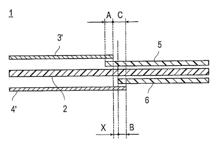
a cathode catalytic layer, length [A (mm) in Fig. 7] of the overlapped
part of the end part of a cathode catalytic layer 3' with the first
gasket layer 5 is preferably over 0 (A>0) . More preferably, the length
A is in the range of 0.2 to 2.0 mm, and most preferably, 0.5 to 1.5
mm. Further, for an anode catalytic layer 41, length [B (mm) in Fig.
7] of the overlapped part of the end part of an anode catalytic layer
4' with the second gasket layer 6 is preferably over 0 and not longer
than 2 mm (0<B2). More preferably, the length B is in the range
of 0.2 to 2.0 mm, and most preferably, 0.5 to 1.5 mm. Furthermore,
length [C (mm) in Fig. 7] between the outer end part of a cathode
catalytic layer 3' and the outer end part of an anode catalytic layer
4' terminating over the outer end part of a cathode catalytic layer,
in the thickness direction of an electrolyte membrane-electrode
assembly 1, is preferably larger than B above (B<C) . More preferably,
the length C is in the range of 2.1 to 4.0 mm, and most preferably,
2.5 to 3. 5 mm. When the length A and length B are within these ranges,
sufficient sealing performance at the end part of a catalytic layer
can be secured.
In the electrolyte membrane-electrode assembly 1 of the present
invention, length [X (mm) in Fig. 7] between the outer end part of
a cathode catalytic layer 3' and the inner end part of the second
gasket layer 6, in the thickness direction of an electrolyte
membrane-electrode assembly 1, is preferably over 0 (X>0). More
preferably, the length X is in the range of 0.1 to 3.8 mm, and most
preferably, 1.0 to 3.0 mm. When the length X is within the range,
deterioration over time of an electrolyte membrane, caused by hot
press in assembly of each layer of an MEA, or fastening pressure on
CA 02610424 2007-11-29
WO 2006/129436 PCT/JP2006/308684
23
cell assembly (compression pressure exerted in sandwiching an MEA
with separators), as described later in detail, can effectively be
suppressed and prevented, and also short circuit phenomenon by contact
between a cathode catalytic layer and an anode catalytic layer can
effectively be suppressed and prevented.
Further, in the electrolyte membrane-electrode assembly of the
present invention, the first gasket layer and/or the second gasket
layer, the overlapped part with the end parts of a cathode/an anode
catalytic layers, or the contact part with the end parts of a cathode/an
anode catalytic layers preferably has at least ability to suppress
gas permeability. By imparting ability to suppress and inhibit gas
permeation to a gasket layer, gas sealing performance at the overlapped
part between the end part of a gasket layer and the end part of a
catalytic layer (in particular, sealing performance against oxygen
gas in a cathode) can be improved. A method for imparting ability
to suppress and inhibit gas permeation to a gasket layer is not
especially limited. For example, the following methods for forming
a gasket layer with a gas impermeable layer and an adhesive layer
can preferably be used, as described later in detail: (1) a method
which comprises selectively providing a sheet having specific
thickness at an overlapped part between the end part of a catalytic
layer and a gasket layer, subjecting it to thermocompression to join
a catalytic layer and an electrolyte membrane by hot press, thereby
sufficiently penetrating adhesive of an adhesive layer into a
overlapped part by pressure of thermocompression exerted thereon;
(2) a method which comprises controlling penetrating amount of
adhesive of an adhesive layer into an overlapped part by suitable
setting the thickness of an adhesive layer or the amount of adhesive
contained in an adhesive layer in the overlapp.ed part; (3) a method
which comprises impregnating a resin in advance to a gasket layer
CA 02610424 2007-11-29
WO 2006/129436 PCT/JP2006/308684
24
(a gas impermeable layer and/or an adhesive layer) corresponding to
the overlapped part; and (4) a method which comprises tightly forming
a catalytic layer corresponding to the overlapped part in advance.
However, a method for imparting ability to suppress and inhibit gas
permeation to a gasket layer is not limited to these methods, and
other well-known methods may be applied.
The electrolyte membrane-electrode assembly of the present
invention can be produced similarly using a well-known method or a
modified method, as appropriate. Specifically, a method for
sequentially forming a cathode catalytic layer, an anode catalytic
layer a first gasket layer, and optionally a second gasket layer,
on a polymer electrolyte membrane, in suitable arrangement, for
example, in the above arrangement can be used.
Therefore, according to a second aspect of the present invention,
a method for producing an electrolyte membrane-electrode assembly
is to be provided, which comprises a step of forming a first gasket
layer at the surface of a cathode catalytic layer side of a polymer
electrolyte membrane, and then forming a cathode catalytic layer,
so that the end part of the cathode catalytic layer overlaps with
the end part of the gasket layer; and a step of forming a second gasket
layer at the surface of an anode catalytic layer side of the polymer
electrolyte membrane, and then forming an anode catalytic layer,
so that the end part of the anode catalytic layer overlaps with the
end part of the gasket layer, wherein the first gasket layer and the
second gasket layer are formed so that area of the effective anode
catalytic layer is made larger than area of the effective cathode
catalytic layer.
According to a third aspect of the present invention, a method
for producing an electrolyte membrane-electrode assembly is to be
provided, which comprises a step of forming a cathode catalytic layer
CA 02610424 2007-11-29
WO 2006/129436 PCT/JP2006/308684
at the surface of a cathode catalytic layer side of a polymer electrolyte
membrane, and then forming a first gasket layer, so as to cover the
end part of the cathode catalytic layer; and a step of forming an
anode catalytic layer at the surface of an anode catalytic layer side
5 of the polymer electrolyte membrane, and then forming a second gasket
layer, so as to cover the end part of the anode catalytic layer, wherein
the first gasket layer and the second gasket layer are formed so that
area of the effective anode catalytic layer is made larger than area
of the effective cathode catalytic layer.
10 According to a fourth aspect of the present invention, a method
for producing an electrolyte membrane-electrode assembly is to be
provided, which comprises a step of forming a first gasket layer at
the surface of a cathode catalytic layer side of a polymer electrolyte
membrane, and then forming a cathode catalytic layer, so that the
15 end part of the cathode catalytic layer overlaps with the end part
of the gasket layer; and a step of forming an anode catalytic layer
at the surface of an anode catalytic layer side of the polymer
electrolyte membrane, and then forming a second gasket layer, so as
to cover the end part of the anode catalytic layer, wherein the first
20 gasket layer and the second gasket layer are formed so that area of
the effective anode catalytic layer is made larger than area of the
effective cathode catalytic layer.
According to the method of the present invention, the cathode
catalytic layer, the first gasket layer, the anode catalytic layer,
25 and optionally the second gasket layer, can correctly and easily be
provided in desired order. In addition, by providing the first gasket
layer and the second gasket layer at the end part of a cathode catalytic
layer and the end part an anode catalytic layer, respectively, an
effective cathode catalytic layer and an effective anode catalytic
layer can be accurately specified to have desired area.
CA 02610424 2007-11-29
WO 2006/129436 PCT/JP2006/308684
26
In the method of the present invention, position adjustment of
each catalytic layer may not necessarily be correct, since the first
gasket layer is formed at the end part of a cathode catalytic layer,
and preferably the second gasket layer at the end part of an anode
catalytic layer. Namely, the end part of the cathode catalytic layer
and the end part of the anode catalytic layer may terminate at nearly
the same position, in the thickness direction of the electrolyte
membrane-electrode assembly. Alternatively, the end part of the
cathode catalytic layer and the end part of the anode catalytic layer
may also terminate at different positions, in the thickness direction
of the electrolyte membrane-electrode assembly. Even in such a case,
a gasket layer may be formed suitably at the end part of a catalytic
layer, so that each catalytic layer has desired size and position.
In this case, the end part of an anode catalytic layer preferably
terminates over the end part of a cathode catalytic layer, in the
thickness direction of an electrolyte membrane-electrode assembly.
As described above, in the present invention, because it is essential
that area of an effective anode catalytic layer is made larger than
area of an effective cathode catalytic layer, use amount of a catalyst
or an electrolyte can be suppressed to a low level, and overlapping
with a gasket layer part can be reduced, by making a cathode catalytic
layer smaller than the size of an anode catalytic layer in advance
like this, which is economically preferable.
For example, in the method according to the second aspect of
the present invention, when the end part of a cathode catalytic layer
3' and the end part of an anode catalytic layer 4' are made to terminate
at nearly the same position in the thickness direction of an electrolyte
membrane-electrode assembly 1, the end parts of a cathode catalytic
layer 3' and an anode catalytic layer 4' are provided in a state as
shown in Fig. 4. In such a case, because gasket layers 5, 6 are present
CA 02610424 2007-11-29
WO 2006/129436 PCT/JP2006/308684
27
between a cathode catalytic layer 3' and an anode catalytic layer
4', there is further advantage that short circuit of the edge parts
caused by contact between the end parts of the catalytic layers
themselves, in being pressed with a gas diffusion layer and the like,
or in lamination as a fuel cell stack, can be prevented. In addition,
in the method according to the third aspect of the present invention,
when the end part of a cathode catalytic layer 3' and the end part
of an anode catalytic layer 4' are made to terminate at nearly the
same position in the thickness direction of an electrolyte
membrane-electrode assembly 1, the end parts of a cathode catalytic
layer 3' and an anode catalytic layer 4' are provided in a state as
shown in Fig. 5. In such a case, because gasket layers 5, 6 are provided
after forming catalytic layers 3' and 4', there are advantages that
a production process is simple and convenient, and in addition, the
region of an effective catalytic layer region can be controlled
accurately and easily, and further the peripheral part of a catalytic
layer can firmly be sealed (in low gas permeation rate) with a gasket
layer, as compared with MEM of Fig. 4. Furthermore, in the method
according to the fourth aspect of the present invention, when the
end part of a cathode catalytic layer 3' and the end part of an anode
catalytic layer 4' are made to terminate at nearly the same position
in the thickness direction of an electrolyte membrane-electrode
assembly 1, the end parts of a cathode catalytic layer 3' and an anode
catalytic layer 4' are provided in a state as shown in Fig. 6. The
structure above is one obtained by combination of the structure of
the methods according to the second and third aspects of the present
invention. Because a gasket layer 5 is present between a cathode
catalytic layer 3' and an anode catalytic layer 4', short circuit
of the.edge parts, in being pressed with a gas. diffusion layer (not
shown) and the like, can be prevented, and furthermore, because the
CA 02610424 2007-11-29
WO 2006/129436 PCT/JP2006/308684
28
end part of an anode catalytic layer is sealed with a gasket layer,
and area of an effective catalytic layer at an anode catalytic layer
can easily be controlled, area of an effective anode catalytic layer
canmore surelybe set larger than area of an effective cathode catalytic
layer. In this case, a reversed pattern of Fig. 6 is also possible,
namely, a method for forming the first gasket layer 5 so as to cover
the end part of a cathode catalytic layer 3', and forming the second
gasket layer 6 between an anode catalytic layer 4' and a polymer
electrolyte membrane 2, so as to be covered with the end part of an
anode catalytic layer 4'. However, by such a method, a part of a
cathode catalytic layer 3' opposing to an overlapped part between
the second gasket layer 6 and an anode catalytic layer 4' , and contacting
with an electrolyte membrane is made to be present. Consequently,
difference between cathode potential and electrolyte potential
becomes large, which induces a carbon corrosion reaction and promotes
corrosion of carbon black, a conductive carrier in a cathode catalytic
layer, and may lower catalytic activity, and thus such a method is
not preferable.
In addition, in the method according to the second aspect of
the present invention, when positions of the end part of a cathode
catalytic layer 3' and the end part of an anode catalytic layer 4'
are displaced in the thickness direction of an electrolyte
membrane-electrode assembly 1, the end parts of a cathode catalytic
layer 3' and an anode catalytic layer 4' are provided in a state as
shown in Fig. 7. In such a case, there is advantages that, because
area of each effective catalytic layer can freely be set depending
of location of a gasket layer, even when correct position adjustment
of the end part of each catalytic layer is not secured, production
process becomes simpler and more convenient, and also because gasket
layers are present between a cathode catalytic layer 3' and an anode
CA 02610424 2007-11-29
WO 2006/129436 PCT/JP2006/308684
29
catalytic layer 41, short circuit of the edge parts, in being pressed
with a gas diffusion layer afterward, or in lamination as a fuel cell
stack, can be prevented. In the method according to the third aspect
of the present invention, when positions of the end part of a cathode
catalytic layer 3' and the end part of an anode catalytic layer 4'
are displaced in the thickness direction of an electrolyte
membrane-electrode assembly 1, the end parts of a cathode catalytic
layer 3' and an anode catalytic layer 4' are provided in a state as
shown in Fig. 8. In such a method, because gasket layers 5, 6 are
provided after forming a catalytic layer, there is advantage, in
addition to the advantage of simple and convenient production process
similarly as described in the method according to the second aspect,
that a production process is more simple and convenient compared with
a method of Fig. 4, and control of a region of an effective catalytic
layer can be carried out accurately and easily, and further a catalytic
layer can firmly be sealed (in low gas permeation rate) with a gasket
layer. In the method according to the fourth aspect of the present
invention, when the end part of a cathode catalytic layer 3' and the
end part of an anode catalytic layer 4' are displaced in the thickness
direction of an electrolyte membrane-electrode assembly 1, the end
parts of a cathode catalytic layer 3' and an anode catalytic layer
4' are provided in a state as shown in Fig. 9. Such structure as
described above, because a gasket layer 5 is present between a cathode
catalytic layer 3' and an anode catalytic layer 41, can prevent short
circuit of the edge parts, in being pressed with a gas diffusion layer
afterward, or in lamination as a fuel cell stack, in addition to the
advantage of simple and convenient production process similarly as
described in the method according to the second aspect, and also,
because an anode catalytic layer 4' side is sealed with a gasket layer
6, and area of effective catalytic layer at an anode catalytic layer
CA 02610424 2007-11-29
WO 2006/129436 PCT/JP2006/308684
4' side can easily be controlled, area of an effective anode catalytic
layer can more surely be set larger than area of an effective cathode
catalytic layer.
In the method of the present invention, in particular, in the
5 methods according to the second to fourth aspect of the present
invention, wherein positions of the end part of a cathode catalytic
layer 3' and the end part of an anode catalytic layer 4' are displaced,
in the thickness direction of an electrolyte membrane-electrode
assembly 1, gap between the end part of a cathode catalytic layer
10 3' and the end part of an effective anode catalytic layer is preferably
not present as far as possible (for example, "X" in Fig. 7 is near
to 0). This is because, if such a gap part is present, even if an
electron (e-) and a proton (H+) generated at this part are transferred
to a cathode catalytic layer, due to larger area of an effective anode
15 catalytic layer than area of an effective cathode catalytic layer,
this proton and electron cannot efficiently react with oxygen at a
cathode and catalytic action does not work effectively. In
consideration of these things, width (X) of a gap part between the
end part of a cathode catalytic layer and the end part of an effective
20 anode catalytic layer is preferably not larger than 1 cm, and more
preferably not larger than 3 mm.
In the present invention, a catalyst component used in a cathode
catalytic layer is not especially limited, so long as it has catalytic
action in a reduction reaction of oxygen, and well-known catalysts
25 can similarly be used. In addition, a catalyst component used in
an anode catalytic layer is also not especially limited, so long as
it has catalytic action in an oxidation reaction of hydrogen, and
well-known catalysts can similarly be used. Specifically, it can
be selected among metals such as platinum, ruthenium, iridium, rhodium,
30 palladium, osmium, tungsten, lead, iron, chromium, cobalt, nickel,
CA 02610424 2007-11-29
WO 2006/129436 PCT/JP2006/308684
31
manganese, vanadium, molybdenum, gallium and aluminum, and alloys
thereof, and the like. Among these, one containing at least platinum
can preferably be used, to improve catalytic activity, poisoning
resistance to CO and the like, heat resistance and the like.
Composition of the alloys is preferably platinum of 30 to 90% by atom
and metals to be alloyed of 10 to 70% by atom, although it depends
on kind of metals to be alloyed. Composition of alloys when alloys
are used as a cathode catalyst can preferably platinum of 30 to 90%
by atom and other metals to be alloyed of 10 to 70% by atom, although
it depends on kind of metals to be alloyed, and can be selected, as
appropriate, by those skilled in the art. As used herein, "alloy"
generally means one composed of a metal element added with one or
more kinds of metal elements or non-metal elements, and a general
name of one having metallic property. Alloy morphology includes
eutectic alloy, so to speak a mixture, wherein component elements
are present as independent crystals, solid solution wherein component
elements are completely dissolved each other, one wherein component
elements form an intermetallic compound or a compound between a metal
and a non-metal, and the like, and any one of these may be included
in the present application. In this case, a catalyst component used
in a cathode catalytic layer and a catalyst component used in an anode
catalytic layer can be selected among the above ones, as appropriate.
In the explanation below, unless otherwise specified, a catalyst
component for a cathode catalytic layer and a catalyst component for
an anode catalytic layer have similar definition for both, and referred
to as "a catalyst component" collectively. However, a catalyst
component for a cathode catalytic layer and an anode catalytic layer
may not be the same and can be selected, as appropriate, so as to
fulfill desired action as described above. .
Shape or size of a catalyst component is not especially limited,
CA 02610424 2007-11-29
WO 2006/129436 PCT/JP2006/308684
32
and similar shape and size as in a well-known catalyst component can
be used. A catalyst component is preferably granular. In this case,
smaller average particle diameter of catalyst particles used in
catalyst ink is preferable due to providing increased effective
electrode surface for proceeding an electrochemical reaction and thus
higher oxygen reduction activity. On the contrarily, practically,
too small average particle diameter provides phenomenon to lower
oxygen reduction activity. Therefore, average particle diameter of
catalyst particles contained in catalyst ink is preferably in the
range of 1 to 30 nm, more preferably 1. 5 to 20 nm, furthermore preferably
2 to 10 nm, and particularly preferably 2 to 5 nm in granular form.
In view of easiness of carrying, it is preferably not smaller than
1 nm, while in view of catalyst utilization rate, it is preferably
not larger than 30 nm. As used herein, "average particle diameter
of catalyst particles" can be measured from crystal diameter
determined by half width of a diffraction peak of a catalyst component,
in X-ray diffraction, or average value of particle diameters of a
catalyst component studied by transmission electron microscope.
In the present invention, the catalyst particles are contained
in catalyst ink as an electrode catalyst carried on a conductive
carrier.
As the conductive carrier, any one can be used so long as it
has specific surface area for carrying catalyst particles in desired
dispersed state and sufficient electron conductivity as a current
collector. A conductive carrier having carbon as a main component
is preferable. Specifically, carbon particles comprising carbon
black, activated carbon, coke, natural graphite, artificial graphite,
and the like may be included. As used herein, "a main component is
carbon" means "to have a carbon atom as a main component", and it
is such concept as contains both "only composed of a carbon atom"
CA 02610424 2007-11-29
WO 2006/129436 PCT/JP2006/308684
33
and "substantially composed of a carbon atom". Optionally, an
element(s) other than a carbon atom may be contained to improve
characteristics of a fuel cell. As used herein, "substantially
composed of a carbon atom" means to allow incorporation of impurity
in an amount of not higher than about 2 to 3% by weight.
Specific BET surface area of the conductive carrier may be any
value sufficient to carry a catalyst component in highly dispersed
state. It is preferably in the range of 20 to 1600 m2/g, and more
preferably 80 to 1200 m2/g. The specific BET surface area below 20
m2/g would provide low dispersibility of a catalyst component and
a polyelectrolyte to the conductive carrier and sufficient performance
of power generation may not be obtained, while the value over 1600
m2/g may lower effective utilization rate of a catalyst component
and a polyelectrolyte.
In addition, size of the conductive carrier is not especially
limited. In view of easiness of carrying, utilization rate of a
catalyst, and control of thickness of an electrode catalytic layer
within a suitable range, an average particle diameter of about 5 to
200 nm, preferably about 10 to 100 nm is suitable.
In an electrode catalyst having a catalyst component carried
onto the conductive carrier, amount of a catalyst component carried
is preferably in the range of 10 to 80% by weight, more preferably
to 70% by weight based on total amount of an electrode catalyst.
The carrying amount over 80% by weight would lower dispersibility
25 of a catalyst component on the conductive carrier, and improvement
of power generation performance is small comparative to the increase
in the carrying amount, and thus may lower economical advantage. On
the other hand, the carrying amount below 10% by weight would lower
catalytic activity per unit mass, requiring high quantity of electrode
30 catalyst to obtain desired power generation performance, and thus
CA 02610424 2007-11-29
WO 2006/129436 PCT/JP2006/308684
34
not preferable. In this case, the carrying amount of a catalyst
component can be studied by means of inductively-coupled plasma
emission spectrometry (ICP).
In a cathode catalytic layer/an anode catalytic layer
(hereinafter referred to simply as "a catalytic layer") of the present
invention, a polyelectrolyte is contained in addition to the electrode
catalyst. The polyelectrolyte is not especially limited, and
well-known one can be used, and material having at least high proton
conductivity can be used. A polyelectrolyte which can be used in
this invention is largely classified into fluorine-based electrolyte
containing a fluorine atom in whole of or a part of polymer skeleton,
and a hydrocarbon-based electrolyte not containing a fluorine atom
in polymer skeleton.
As the fluorine-based electrolyte, perfluorocarbon sulfonic
acid-based polymers such as Nafion (registered trade mark; produced
from DuPont Co., Ltd.), Aciplex (registered trade mark; produced from
Asahi Kasei Corp.) and Flemion (registered trade mark; produced from
Asahi Glass Co., Ltd.), polytrifluorostyrene sulfonic acid-based
polymers, perfluorocarbon phosphonic acid-based polymers,
trifluorostyrene sulfonic acid-based polymers,
ethylentetrafluoroethylene-g-styrene sulfonic acid-based polymers,
ethylene-tetrafluoroethylene copolymers, polyvinylidene
fluoride-perfluorocarbon sulfonic acid-based polymers, and the like
may be advantageously included.
As the hydrocarbon-based electrolyte, polysulf one sulf onic acid,
polyarylether ketone sulfonic acid, polybenzimidazol alkylsulfonic
acid, polybenzimidazol alkylphosphonic acid, polystyrene sulfonic
acid, polyether ether ketone sulf onic acid, polyphenyl sulf onic acid,
and the like may be advantageously included..
As a polyelectrolyte, ones containing a fluorine atom may be
CA 02610424 2007-11-29
WO 2006/129436 PCT/JP2006/308684
preferably used and, among them, fluorine-based electrolyte such as
Nafion (registered trade mark; produced from DuPont Co., Ltd.),
Aciplex (registered trade mark; produced from Asahi Kasei Corp.) and
Flemion (registered trade mark; produced from Asahi Glass Co. , Ltd.)
5 may be more preferably used.
In addition, carrying of a catalyst component on a conductive
carrier can be executed by a well-known method. For example,
well-known methods such as an impregnation method, a liquid-phase
reduction carrying method, an evaporation to dryness method, a colloid
10 adsorption method, a spray pyrolysis method, and a reversed micelle
method (a micro emulsion method) can be used, or commercial products
may be used as an electrolyte catalyst.
In the method of the present invention, a catalytic layer is
formed by applying a catalyst ink composed of an electrode catalyst,
15 a polyelectrolyte and a solvent, as described above, onto the surface
of a polymer electrolyte membrane (or onto the surface of a polymer
electrolyte membrane in partially covered state with a gasket layer).
In this case, a solvent is not especially limited, and a usual solvent
which has been conventionally used for forming a catalytic layer can
20 similarly be used. Specifically, water, and lower alcohols such as
ethanol and 2-propanol can be used. In addition, use amount of a
solvent is also not especially limited, and the similar amount
well-known can be used, and in catalyst ink, an electrode catalyst
may be used in any amount so long as it is such amount as sufficiently
25 fulfills desired action, namely, catalytic action for an oxidation
reaction of hydrogen (an anode side), and a reduction reaction of
oxygen (a cathode side) . An electrode catalyst is preferably present
in an amount in the range of 5 to 30% by weight, more preferably 9
to 20o.by weight in a catalyst ink.
30 The catalyst ink used in the present invention may contain a
CA 02610424 2007-11-29
WO 2006/129436 PCT/JP2006/308684
36
thickener. Use of a thickener is effective in such a case when catalyst
ink will not be applied well onto a transcription board, and the like.
A thickener used therein is not especially limited and a well-known
thickener can be used, for example, glycerin, ethylene glycol (EG) ,
polyvinyl alcohol (PVA) and propylene glycol (PG) may be included.
Among these, propylene glycol (PG) is pref erably used. This is because,
by use of propylene glycol (PG) , boiling point of catalyst ink increases,
to lower an evaporation rate of the solvent. Therefore, for example,
solvent evaporation rate in catalyst ink applied can be decreased,
and crack generation 10 in a catalytic layer 3' after the drying process
can be suppressed and prevented, by the addition of PG in catalyst
ink during formation of a catalytic layer on an electrolyte membrane
1 by a transcription method, and first when catalyst ink is applied
using a screen printer onto a transcription board other than a membrane,
and dried (see Fig. 33) . By transcribing a catalytic layer with little
crack onto a membrane by using such a catalyst ink, concentration
of mechanical stress to a membrane in an OCV duration test can be
reduced, which can result in improvement of durability of an MEA.
In the case of using a thickener, the addition amount thereof is not
especially limited, so long as it is about such amount not to interrupt
the effects of the present invention. It is preferably in the range
of 5 to 65% by weight, based on total weight of catalyst ink. In
particular, when PG is used as a thickener, the addition amount thereof
is preferably 10 to 30% by weight, based on total weight of catalyst
ink.
A method for preparing catalyst ink according to the present
invention is not especially limited, so long as it provides suitable
mixing with an electrode catalyst, an electrolyte and a solvent, and
optionally a water repellent polymer and/or a thickener. For example,
catalyst ink can be prepared by adding an electrolyte in a polar solvent,
CA 02610424 2007-11-29
WO 2006/129436 PCT/JP2006/308684
37
heating and stirring the resultant mixture, to dissolve an electrolyte
in a polar solvent, and then adding an electrode catalyst thereto.
Alternatively, catalyst ink may be prepared by once dispersing or
suspending an electrolyte in a solvent, and then mixing the dispersion
or suspension with an electrolyte. In addition, a commercial
available electrolyte solution having an electrolyte prepared into
another solvent in advance (for example, a Nafion solution produced
from DuPont Co., Ltd.: a 1-propanol solution having Nafion dispersed
or suspended in a concentration of 5% by weight) may be used.
Each catalytic layer may be formed by applying the catalyst ink
on a polymer electrolyte membrane, or on a polymer electrolyte membrane
while covering a part of a gasket layer. In this case, formation
conditions of a cathode catalytic layer and an anode catalytic layer
on a polymer electrolyte membrane are not especially limited, and
a well-known method can be used similarly, or after modification,
as appropriate. For example, catalyst ink is applied on a polymer
electrolyte membrane so as give a thickness after drying of 5 to 20
pm, and dried the coat in a vacuum dryer or under reduced pressure
at 25 to 150 C, preferably at 60 to 120 C, for 5 to 30 minutes, more
preferably for 10 to 20 minutes. When thickness of a catalytic layer
is not sufficient in one process, the similar application and drying
processes may be repeated until desired thickness is obtained.
Further, in the present invention, a gasket layer may be any
one so long as it is impermeable to gas, in particular oxygen or hydrogen
gas. In general, it is composed of an adhesive layer for adhering
a polymer electrolyte membrane with the end parts of a cathode catalytic
layer and an anode catalytic layer, and an impermeable layer formed
of gas impermeable material.
Amaterial forming an impermeable layer is not especially limited,
so long as it is impermeable against oxygen or hydrogen gas after
CA 02610424 2007-11-29
WO 2006/129436 PCT/JP2006/308684
38
a membrane is obtained. Specifically, polyethylene naphthalate(PEN),
polyethylene terephthalate (PET), polytetrafluoroethylene (PTFE),
polyvinylidene fluoride (PVDF), and the like are included.
A material which can be used as an adhesive layer is also not
especially limited, so long as it enables to firmly adhere a polymer
electrolyte membrane or a cathode catalytic layer and an anode
catalytic layer with a gasket layer. The adhesive layer has also
preferably low gas impermeability. When such an adhesive layer is
adopted, the adhesive layer also enables to serve as a gas impermeable
layer in an MEA produced, which ispreferable. Specifically, hot-melt
type adhesive such as polyolefin, polypropylene and a thermoplastic
elastomer, acrylic adhesive, polyester, and olefin type adhesive such
as polyolefin can be used. Among these, as material forming an adhesive
layer, hot-melt type adhesive is preferably used. Because hot-melt
type adhesive does not soften at normal temperature, it has such
advantage that position adjustment becomes simple and convenient in
a step of providing a gasket layer. In addition to this advantage,
it also has advantage that the production can be easily carried out
for a short time, as compared with thermosetting-type adhesive.
Furthermore, depending on kind of an adhesive layer to adhere a gasket
layer at the end part of a catalytic layer, gap may be generated between
a catalytic layer and a gasket layer, during sealing a gasket layer.
For example, when such gap is generated at a cathode, cross-leak of
oxygen gas occurs from this gap, which induces oxidative deterioration
of an electrolyte membrane caused by formation of hydrogen peroxide,
and meaning of mounting a gasket layer may be reduced. On the other
hand, when hot-melt type adhesive is adopted as adhesive, the end
part of a catalytic layer can be sealed by the adhesive layer softened
by hot.press treatment in sealing. Therefore, risk of generating
gap in sealing process of the end part of a catalytic layer with a
CA 02610424 2007-11-29
WO 2006/129436 PCT/JP2006/308684
39
gasket layer can be reduced, and an MEA with high reliability can
be produced. In this case, softening point of hot-melt type adhesive
is not especially limited, and can be selected, as appropriate, in
consideration of material used in an impermeable layer or a catalytic
layer. Preferably, hot-melt type adhesive has softening point higher
than operation temperature and within about the temperature range
not damaging an electrolyte membrane or a catalytic layer in production.
When such condition is satisfied, adhesive does not soften, even by
operation of a fuel cell having the MEA incorporated practically
thereinto, and firm sealing performance (low gas permeation rate)
between the end part of a catalytic layer and a gasket layer can be
maintained, and an MEA can be produced without damage (without lowering
of performance or fracture) of an electrolyte membrane or a catalytic
layer, even if heated in producing an MEA, by assembling a membrane
and an electrolyte membrane, and the like, as described later.
Specifically, melting point of hot-melt type adhesive is 50 to 170 C
and most preferably 90 to 150 C.
A formation method for a gasket layer is not especially limited,
and a well-known method can be used. For example, such a method can
be used for applying the adhesive on a polymer electrolyte membrane,
or on a polymer electrolyte membrane while covering the end part of
a catalytic layer, so as to give thickness of 5 to 30 pm, and then
applying the gas impermeable material, so as to give thickness of
10 to 200 pm, and curing by heating at 50 to 170 C for 10 seconds
to 10 minutes. Alternatively, adhesive may be applied onto the
impermeable layer after forming gas impermeable material in sheet
form in advance, to form a gasket layer. Then, it may be adhered
onto a polymer electrolyte membrane, or onto a polymer electrolyte
membrane while covering a part of a gasket layer. In this case,
thickness of the impermeable layer is not especially limited. It
CA 02610424 2007-11-29
WO 2006/129436 PCT/JP2006/308684
is preferably in the range of 15 to 40 }gym. Similarly, thickness of
the adhesive layer is also not especially limited. It is preferably
in the range of 10 to 25 pm.
An electrolyte membrane used in the MEA of the present invention
5 is not especially limited, and a membrane composed of a similar
polyelectrolyte as used in an electrode catalytic layer maybe included.
In addition, a solid polymer type electrolyte membrane which is
commercially available, such as a fluorine-based polyelectrolyte,
including a perfluorosulfonic acid membrane represented by such as
10 various Nafion grades (registered trade mark of DuPont Co., Ltd.)
and Flemion produced from DuPont Co., Ltd.; an ion-exchange resin
produced from Dow Chemical Co.,Ltd. ,an ethylene-tetrafluoroethylene
copolymer-type membrane, a resin membrane based on a trifluorostyrene
polymer; and a hydrocarbon-based resin membrane having asulfo group,
15 a membrane obtained by micro porous membrane impregnated with a liquid
electrolyte, and a membrane obtained by a porous substance membrane
filled with a polyelectrolyte, and the like may be used. Although
an polyelectrolyte used in the polymer electrolyte membrane and a
polyelectrolyte used in each electrode catalytic layer may be the
20 same or different, the same one is preferably used in view of improvement
of adhesion between each electrode catalytic layer and a polymer
electrolyte membrane.
Thickness of the polymer electrolyte membrane may be determined,
as appropriate, in consideration of characteristics of an MEA to be
25 obtained. It is preferably in the range of 5 to 300 }gym, more preferably
10 to 200 pm, and particularly preferably 15 to 100 pm. In view of
strength in membrane formation or durability in operation of an MEA,
not lower than 5 pm is preferable, and in view of output characteristics
in operation of an MEA, not higher than 300.pm is preferable.
30 In addition, as the polymer electrolyte membrane, one obtained
CA 02610424 2007-11-29
WO 2006/129436 PCT/JP2006/308684
41
by porous thin film formed from polytetrafluoroethylene (PTFE),
polyvinylidene fluoride (PVDF) which is impregnated with an
electrolyte component such as phosphoric acid or ionic liquid may
be used, as well as fluorine-based polyelectrolyte or a hydrocarbon
resin-based membrane having a sulfo group.
In the present invention, the first gasket layer and further
preferably the second gasket layer preferably ones comprises a gas
impermeable layer and an adhesive layer formed thereon, as described
above. In such a case, as a method for producing an MEA which can
particularly preferably be used is a method for producing an
electrolyte membrane-electrode assembly which comprises a catalytic
layers-forming step of forming a cathode catalytic layer and an anode
catalytic layer at each surface of a polymer electrolyte membrane,
so that area of the anode catalytic layer is made larger than area
of the cathode catalytic layer; a gasket layer-locating step of
locating a first gasket layer having a first adhesive layer formed
on a first gas impermeable layer, on at least a part of the peripheral
part of the polymer electrolyte membrane, so that the first adhesive
layer and the polymer electrolyte membrane are in opposing position,
and locating a second gasket layer having a second adhesive layer
formed on a second gas impermeable layer, on at least a part of the
end part or the peripheral part of the polymer electrolyte membrane,
so that the second adhesive layer and the polymer electrolyte membrane
are in opposing position; and an adhering step of adhering the first
gasket layer and the second gasket layer with the polymer electrolyte
membrane, by pressing a laminate obtained by the catalytic
layers-forming step and the gasket layer-locating step.. This method
forms a fifth aspect of the present invention.
The method according to the fifth aspect of.the present invention
will be explained below.
CA 02610424 2007-11-29
WO 2006/129436 PCT/JP2006/308684
42
First, a cathode catalytic layer and an anode catalytic layer
are formed at each surface of a polymer electrolyte membrane, so that
area of an anode catalytic layer becomes larger than area of a cathode
catalytic layer (catalytic layers-forming step) In this step, the
explanation about a catalyst ink used in each catalytic layer (a
catalyst component, a conductive carrier, a polyelectrolyte, and the
like) , an electrolyte membrane, and a method for forming a catalytic
layer to an electrolyte membrane are omitted, because they are similar
as in the second and the third aspects as above.
In the method for production of the present invention, then a
gasket layer-locating step of locating a gasket layer is carried out.
Either of the catalytic layers-forming step for forming a
catalytic layer, or the gasket layer-locating step of locating a gasket
layer may be carried out first. In some cases, the catalytic
layers-forming step and the gasket layer-locating step may be carried
out simultaneously.
In the gasket layer-locating step according to the present
invention, position of the first gasket layer on the peripheral part
of a cathode catalytic layer, and position of the second gasket layer
on the peripheral part of an anode catalytic layer may be suitably
selected. Specifically, in the gasket layer-locating step, gasket
layers 5, 6 can be provided, for example, so that the end part of
the first gasket layer 5 and the end part of a cathode catalytic layer
3' terminate nearly at the same position, and the end part of the
second gasket layer 6 and the end part of an anode catalytic layer
4' terminate nearly at the same position, as shown in Fig. 11. By
such a location, sealing between a catalytic layer 3' (or 4') and
a gasket layer 5 (or 6) can be carried out in highest precision, and
gap occurring between them can be suppressed to the minimum. When
a gasket layer is provided like this, so that the end part of a catalytic
CA 02610424 2007-11-29
WO 2006/129436 PCT/JP2006/308684
43
layer 3' (or 4' ) and the end part of a gasket layer 5 (or 6) terminate
nearly at the same position, an adhesive layer 5b (or 6b) formed in
a gasket layer 5 (or 6) preferably has at least partially a thin part
wherein thickness of the part is thinner as compared with the other
part, as shown in Fig. 12. By such a structure, protrusion of extra
adhesive layer from a gasket layer can be suppressed and yield by
an MEA production can be improved. In addition, when such suppression
effects of protrusion of extra adhesive layer is desired to be fulfilled
more significantly, at least either of the gasket layers can have
an exposed part wherein no adhesive layer is present, as shown in
Fig. 13.
On the other hand, location of a gasket layer may be carried
out by making a certain degree of gap between a gasket layer and the
end part of a catalytic layer. When a gasket layer is provided like
this bymaking a certain degree of gap between the end part of a catalytic
layer, for example, thickness of a part of (in particular, an inner
end part (a catalytic layer side)) of an adhesive layer 5b (or 6b)
formed in a gasket layer 5 (or 6) may preferably be increased, as
compared with other part, as shown in Fig. 14. According to such
an embodiment, even if a certain degree of gap is present between
a gasket layer 5 (or 6) and the end part of a catalytic layer 3' (or
4'), in a gasket layer-locating step, an adhesive layer 5b (or 6b)
having increased thickness is ensured to serve as an adhesive layer
for filling this gap in an adhering step, and tight sealing between
a gasket layer and the end part of a catalytic layer can further be
secured. Such an embodiment is particularly effective, when hot-melt
type adhesive is used as adhesive.
Alternatively, an adhesive layer maybe formed in plural in convex
state in the direction from the outer end part (outside of an MEA)
toward the inner end part (a catalytic layer side) of a gasket layer,
CA 02610424 2007-11-29
WO 2006/129436 PCT/JP2006/308684
44
as shown in Fig. 15. Such plural hot-melt type adhesive layers 5b
(or 6b) are integrated into one piece by melting in the adhering step.
According to such an embodiment also, even if a certain degree of
gap is present between a gasket layer 5 (or 6) and the end part of
a catalytic layer 3' (or 4') , in a gasket layer-locating step, tight
sealing between a gasket layer and the end part of a catalytic layer
can further be attained.
As mentioned above, even if gap is present between the end part
of a catalytic layer 3' (or 4') and a gasket layer 5 (or 6), in a
gasket layer-locating step, this gap can be filled with adhesive (in
particular, hot-melt type adhesive) by press treatment in an adhering
step, as shown in Fig. 16. Therefore, since according to such a method
for production, it is not necessary to provide a gasket layer 5 (or
6) with accurate coincidence with the end part of a catalytic layer
3' (or 4') , the production can be proceed simpler andmore conveniently.
When a gasket layer-locating step is carried out after a catalytic
layers-forming step, the method of the present invention may further
comprise a guide member-locating step which comprises locating a guide
member 7 to adjust the position of the gasket layer, between a catalytic
layers-forming step and a gasket layer-locating step, as shown in
Fig. 17. By this guide member-locating step, a gasket layer can be
provided at more accurate position and an MEA with high reliability
can be produced. In this case, a guide member used in the guide
member-locating step is removed after a gasket layer is located in
a gasket layer-locating step, and before an adhering step.
Specific embodiments on component material of a guide member,
and the like are not especially limited. Amaterial with low poisoning
risk of a polymer electrolyte membrane or a catalytic layer may be
preferably used. Typically, fluorocarbon resins such as
polytetrafluoroethylene (PTFE), perfluoroalkoxy (PFA) and
CA 02610424 2007-11-29
WO 2006/129436 PCT/JP2006/308684
polyvinylidene fluoride (PVDF); acrylic resin, epoxy resin, phenolic
resin, polyvinyl chloride, glass, wood, metal, and the like can be
cited. Naturally, a guide member may be composed of another material.
Thickness of a guide member is not also especially limited, and
5 can be set appropriately, so that guiding step for locating a gasket
layer can efficiently be carried out. As an example, thickness of
a guide member is preferably in the range of about 100 pm to about
2 cm, more preferably about 100 pm to about 3 mm. However, a guide
member having thickness without this range may be used, depending
10 on conditions.
In the method for production of the present invention, an adhering
step is carried out after a catalytic layers-forming step and a gasket
layer-locating step. In the adhering step, a laminate obtained by
a catalytic layers-forming step and a gasket layer-locating step is
15 pressed. By this process, a gasket layer and a polymer electrolyte
membrane are adhered through an adhesive layer of a gasket layer.
Press conditions in the adhering step are also not especially
limited, and conventionally well-known knowledge can be referred to,
as appropriate, depending on kind of adhesive used, and the like.
20 As an example of preferable conditions, a press pressure is preferably
in the range of 0.05 to 4.0 MPa, more preferably 0.1 to 2.0 MPa, and
a press time is preferably in the range of 1 second to 10 minutes,
more preferably 10 seconds to 1 minute. In addition, when hot-melt
type adhesive is used as adhesive, hot press is preferably carried
25. out in an adhering step. In this case, press temperature is preferably
in the range of 50 to 170 C, more preferably 90 to 150 C.
As above, although only a method for direct formation of an anode
catalytic layer and a cathode catalytic layer or a gasket layer on
a polymer electrolyte membrane by directly applying a catalyst ink,
30 the MEA of the present invention may be produced by other methods
CA 02610424 2007-11-29
WO 2006/129436 PCT/JP2006/308684
46
such as a transcription method. A method for production in such a
case is not especially limited, and a well-known transcription method
can be used similarly, or after suitable modification. For example,
the following method can be used. Specifically, catalyst ink prepared
by a similar method as above is applied on a transcription board and
dried to form an electrode catalytic layer. In this case, as a
transcription board, a well-known sheet such as a polyester sheet
including a PTFE (polytetrafluoroethylene) sheet and a PET
(polyethylene terephthalate) sheet can be used. A transcription
board can be selected, as appropriate, depending on kind of catalyst
ink used (in particular, a conductive carrier such as carbon in ink) .
In this process, thickness of an electrode catalytic layer is not
especially limited, so long as it is such thickness as ensuring
sufficient catalytic action for oxidation of hydrogen (an anode side)
and for reduction of oxygen (a cathode side) , and thickness similar
to a conventional one can be used. Specifically, thickness of an
electrode catalytic layer may be in the range of 1 to 30 pm, more
preferably 1 to 20 pm. In addition, an application method of catalyst
ink onto a transcription board is not especially limited, and a
well-known method such as a screen printing method, a deposition method
or a spray method can similarly be applied. Furthermore, drying
conditions of an electrode catalytic layer applied is also not
especially limited, so long as it enables to completely remove a polar
solvent from an electrode catalytic layer. Specifically, a layer
applied with catalyst ink (an electrode catalytic layer) may be dried
in a vacuum dryer at room temperature to 100 C, more preferably at
50 to 80 C for 30 to 60 minutes. When thickness of a catalytic layer
is not sufficient in one process, the application and drying process
can be. repeated until desired thickness is obtained. Then after
sandwiching a polymer electrolyte membrane with the resultant
CA 02610424 2007-11-29
WO 2006/129436 PCT/JP2006/308684
47
electrode catalytic layers, the laminated layer may be subjected to
hot press. In this case, hot press conditions are not especially
limited, so long as an electrode catalytic layer can be sufficiently
tightly assembled with a polymer electrolyte membrane. The hot press
may be preferably carried out at 100 to 200 C, more preferably 110
to 170 C, under pressure in the range of 1 to 5 MPA for an electrode
surface. Under such conditions, adhesion between the polymer
electrolyte membrane and the electrode catalytic layers can be
enhanced. The MEA with the electrode catalytic layers and the polymer
electrolyte membrane can be obtained by peeling the transcription
board, after hot press.
A gasket layer and a catalytic layer may be formed at the same
time on a transcription board by forming a catalytic layer on a
transcription board, locating an gas impermeable layer at the
peripheral part of the catalytic layer, and applying adhesive on the
gas impermeable layer, in formation of a catalytic layer by the
transcription method. According to such an embodiment, at the same
time of transcription of a catalyst, a gasket layer is transcribed
onto a polymer electrolyte membrane. Further, press in transcription
step can serve also as an adhering step in the method for production
of the present invention, which can provide transcription of a gasket
layer and a catalytic layer onto a polymer electrolyte membrane in
tightly adhered state between a gasket layer and the end part of a
catalyst.
The MEA of the present invention may further have a gas diffusion
layer in general, as described in detail below. In this case, a gas
diffusion layer is preferably adhered to each electrode catalytic
layer, by peeling a transcription board from the MEA comprising
electrode catalytic layers and a polymer electrolyte membrane, and
sandwiching the resultant MEA with gas diffusion layers to obtain
CA 02610424 2007-11-29
WO 2006/129436 PCT/JP2006/308684
48
an assembly having the MEA sandwiched with the gas diffusion layers.
Alternatively, it is also preferable that electrode catalytic layers
are formed on each gas diffusion layer to assemblies of electrode
catalytic layer and gas diffusion layer, a polymer electrolyte
membrane is sandwiched with the assemblies, and then the laminate
is joined by hot press.
In this case, a gas diffusion layer used herein is not especially
limited, and a well-known one can similarly be used. For example,
conductive and porous sheet-like materials such as carbon-based fabric,
paper-like paper making substance, felt and non-woven fabric may be
included as a substrate. Thickness of the substrate maybe determined,
as appropriate, in consideration of characteristics of the resultant
gas diffusion layer. It is advantageously in the range of about 30
to about 500 }gym. Thickness below 30 pm may not provide sufficient
mechanical strength, while thickness over 500 pmwould make permeation
distance of gas or water too long which is not desirable.
A method for forming an electrode catalytic layer on the surface
of a gas diffusion layer is not especially limited, and a well-known
method such as a screen printing method, a deposition method or a
spray method can similarly be applied. In addition, forming
conditions of an electrode catalytic layer on the surface of a gas
diffusion layer are not especially limited, and similar conditions
as used in a conventional method is applicable, depending on a specific
formation method as above.
The gas diffusion layer preferably may have a water repellant
agent incorporated into the substrate in order to enhance water
repellency to prevent flooding phenomenon. The water repellant agent
is not especially limited, and fluorine-based polymeric material such
as polytetrafluoroethylene (PTFE), polyvinylidene fluoride (PVDF),
polyhexafluoropropylene, a copolymer of
CA 02610424 2007-11-29
WO 2006/129436 PCT/JP2006/308684
49
tetrafluoroethylene-hexafluoropropylene; polypropylene,
polyethylene, and the like may be included.
The gas diffusion layer may be have a carbon particles layer
composed of assembly of carbon particles, including water repellent
agent on the substrate, to further enhance water repellency.
The carbon particles are not especially limited, and conventional
general ones such as carbon black, graphite and expandable graphite
may be used. Among these, carbon black such as oil furnace black,
channel black, lamp black, thermal black and acetylene black may be
preferably used, because of having superior electron conductivity
and high specific surface area. Particle diameter of the carbon
particles is preferably in the range of about 10 to about 100 nm.
By these, high water drainage performance due to capillary force can
be attained and improvement of contact ability with a catalytic layer
can be also attained.
As a water repellent agent used for the carbon particles layer,
similar ones as the water repellent agents used in the substrate may
be included. Among these, fluorine-based polymer material may be
preferably used due to its superior water repellency, corrosion
resistance in an electrode reaction, and the like.
As for mixing ratio of carbon particles and a water repellent
agent in the carbon particles layer, an excess amount of carbon
particles may not provide water repellency as expected, and an excess
amount of water repellent agent may not provide sufficient electron
conductivity. In consideration of theses, mixing ratio of carbon
particles and a water repellent agent is preferably about 90:10 to
about 40:60 in weight ratio.
Thickness of the carbon particles layer may be determined
suitably, in consideration of water repellency of the resultant gas
diffusion layer.
CA 02610424 2007-11-29
WO 2006/129436 PCT/JP2006/308684
When a water repellent agent is incorporated in a gas diffusion
layer, it may be carried out using a general method for water repellent
treatment. For example, a method which comprises immersing a
substrate used in a gas diffusion layer in a dispersion of a water
5 repellent agent, and then heating and drying the layer in an oven,
and the like may be included.
When a carbon particles layer is formed on the substrate in a
gas diffusion layer, such a method may be used that carbon particles,
a water repellent agent, and the like may be dispersed in a solvent
10 such as water, perfluorobenzene, dichloropentafluoropropane, an
alcoholic solvent such as methanol and ethanol, to prepare slurry,
which is then applied onto a substrate and dried, or the slurry is
once dried and crushed to obtain powders, which are applied onto the
gas diffusion layer. Subsequently, it is preferably subjected to
15 heat treatment at about 250 to 400 C using a muffle furnace or a firing
furnace.
A method for producing an assembly containing an electrode
catalytic layer and an electrolyte membrane, and preferably a gas
diffusion layer is not limited to the method above. Namely, a method
20 which comprises applying catalyst ink onto an electrolyte membrane,
and drying, and treating by hot press to make electrode catalytic
layers with a solid polymer electrolyte membrane assembled, and then
sandwiching the resultant assembly by gas diffusion layers to obtain
an MEA; and a method which comprises applying catalyst ink onto the
25 gas diffusion layer, and drying to form electrode catalytic layers,
and then treating by hot press with an electrolyte membrane to join
the electrode catalytic layers with the electrolyte membrane, and
the like, and various other well-known technologies may be used, as
appropriate.
30 The electrolyte membrane-electrode assembly of the present
CA 02610424 2007-11-29
WO 2006/129436 PCT/JP2006/308684
51
invention, and the electrolyte membrane-electrode assembly produced
by the method of the present invention can suppress deterioration
of an electrolyte component contained in an electrolyte
membrane-electrode assembly, as described above. In addition, by
providing a gasket layer, area and position of a catalytic layer can
easily be determined, and because correct position adjustment of each
catalytic layer in advance is not required, it is significantly
desirable inconsideration of industrial mass production. Therefore,
by using such an electrolyte membrane-electrode assembly, a fuel cell,
whose production process is easy and having superior durability and
high reliability, can be provided.
Kind of the fuel cell is not especially limited. Although a
polyelectrolyte type fuel cell has been described as an example in
the above Description, other ones may be also included such as an
alkali type fuel cell, a direct methanol type fuel cell, and a micro
fuel cell. Among these, a polyelectrolyte type fuel cell is preferably
included, because compact sizing, high density and high output can
be attained. In addition, the fuel cell is useful not only as power
source for mobile objects such as a vehicle with limited mounting
space, and also as stationary power source, in particular, it can
be particularly suitably used in automotive applications wherein
start/stop of a system or output variation is frequently occurs. The
MEA of the present invention, because of fulfilling particular effects
on deterioration of an electrolyte membrane in idle stop (OCV) state,
fulfills significant effects in a polyelectrolyte type fuel cell,
an alkali type fuel cell, a direct methanol type fuel cell and a micro
fuel cell, wherein deterioration of the electrolyte membrane causes
a problem. Therefore, application to a phosphoric acid type fuel
cell is.not included, wherein such deterioration of an electrolyte
membrane is not viewed as a problem.
CA 02610424 2007-11-29
WO 2006/129436 PCT/JP2006/308684
52
The polyelectrolyte type fuel cell is useful as power source
for mobile objects such as an automobile with limited mounting space,
in addition to stationary power source. Among these, it is
particularly preferable to be used as power source for mobile objects
such as an automobile, wherein corrosion of a carbon carrier caused
by high power output required after operation stop for relatively
long time, and deterioration of a polyelectrolyte caused by taking
up of high output voltage during operation easily occur.
Construction of the fuel cell is not especially limited, and
conventionally well-known technology maybe utilized, as appropriate.
It generally has structure wherein an MEA is sandwiched by separators.
As the separator, any one can be used without limitation, so
long as it. has been conventionally well-known, including carbon
material such as high density carbon graphite and a carbon plate,
metal material such as stainless steel, and the like. A separator
serves to separate air and fuel gas, and may be formed with a flow
channel path to secure a flow. Thickness or size of a separator and
shape of a flow channel path are not especially limited, and may be
determined, as appropriate, in consideration of output
characteristics of the resultant fuel cell.
In addition, a gas seal part may further be provided at a part
wherein a catalytic layer is not formed on a gasket layer, to prevent
outward leak of gas fed to each catalytic layer. As material composing
the gas seal part, rubber material such as fluorocarbon rubber,
silicone rubber, ethylene-propylene rubber (EPDM) and
polyisobutylene rubber; fluorine-based polymeric material such as
polytetrafluoroethylene (PTFE), polyvinylidene fluoride (PVDF),
polyhexafluoropropylene, and a copolymer of
tetraf luoroethylene-hexaf luoropropylene; a thermoplastic resin such
as polyolefin and polyester, and the like are included. Thickness
CA 02610424 2007-11-29
WO 2006/129436 PCT/JP2006/308684
53
of the gas seal part may be in the range of about 2 mm to about 50
pm, desirably about 1 mm to about 100 pm.
Further, a stack maybe formed by laminating and connecting plural
MEA's in series through separators, to obtain desired voltage and
the like, by a fuel cell. Shape of a fuel cell, and the like are
not especially limited, and may be determined, as appropriate, so
that desired cell characteristics such as voltage can be obtained.
Examples
The present invention is described more specifically with
referring to Examples and Comparative Examples, however, the present
invention is by no means limited thereto.
Example 1
An MEA as shown in Fig. 18 was prepared as follows:
(Preparation of anode catalytic layer 4')
To carbon carrier (Ketjenblack EC, produced from Ketjen Black
International Co. , Ltd. ; BET surface area=800 m2/g) having Pt particles
carried thereon in a concentration of Pt carried of 50% by weight,
purified water was added in an amount of 4 times weight of the carbon
carrier carried with Pt particles. After the mixture was subjected
to defoaming under reduced pressure for 5 minutes, 0.5 time weight
of n-propyl alcohol was added thereto. Then, a solution containing
20% by weight of Nafion (registered trade name; produced from DuPont
Co., Ltd., DE520) as an electrolyte was further added. The solution
contained electrolyte at a weight ratio of solid content to the carbon
carrier (Carbon (carbon)/Ionomer (electrolyte)) of 1.0/0.9.
The resultant mixed slurry was dispersed by means of an ultrasonic
homogenizer and subjected to defoaming under reduced pressure, to
prepare catalyst slurry. The resultant catalyst slurry was applied
CA 02610424 2007-11-29
WO 2006/129436 PCT/JP2006/308684
54
by a screen printing method on one surface of a polytetrafluoroethylene
sheet (7.5 cmx7.5 cm, a thickness of 0.08 mm) in an amount so as to
give desired thickness, and the coating was dried at 60 C for 24 hours.
Size of the anode catalytic layer produced by a screen printing method
was set to be 5.2 cmx5.2 cm. In addition, the coating layer on the
polytetrafluoroethylene sheet was adjusted so that Pt content was
0.4 mg /cm2 .
(Preparation of cathode catalytic layer 3')
To carbon carrier (Ketjenblack EC, produced from Ketjen Black
International Co., Ltd. ; BET surface area=800 m2/g) having Pt particles
carried thereon in a concentration of Pt carried of 50% by weight,
purified water was added in an amount of 4 times weight of the carbon
carrier carried with Pt particles. After the mixture was subjected
to defoaming under reduced pressure for 5 minutes, 0.5 time weight
of n-propyl alcohol was added thereto. Then, a solution containing
20% by weight of Nafion (registered trade name; produced from DuPont
Co., Ltd., DE520) as an electrolyte was further added. The solution
contained electrolyte at a weight ratio of solid content to the carbon
carrier (Carbon (carbon)/Ionomer (electrolyte)) of 1.0/0.9.
The resultant mixed slurry was dispersedbymeans of an ultrasonic
homogenizer and subjected to defoaming under reduced pressure, to
prepare catalyst slurry. The resultant catalyst slurry was applied
by a screen printing method on one surface of a polytetrafluoroethylene
sheet (7.5 cmx7.5 cm, a thickness of 0.08 mm) in an amount so as to
give desired thickness, and the coating was dried at 60 C for 24 hours.
Size of the cathode catalytic layer produced by a screen printing
method was set to be 5.1 cmx5.1 cm. In addition, the coating layer
on the polytetrafluoroethylene sheet was adjusted so that Pt content
was 0.4 mg/cm2.
(Preparation of electrolyte membrane-electrode assembly (MEA) 1)
CA 02610424 2007-11-29
WO 2006/129436 PCT/JP2006/308684
Using a fluorine-based electrolyte membrane without a
reinforcing layer (7.5 cmx7.5 cm, a membrane thickness of 25 pm) as
a solid polymer electrolyte membrane, this solid polymer electrolyte
membrane was overlapped on the anode catalytic layer formed on
5 polytetrafluoroethylene sheet, and further the cathode catalytic
layer formed on polytetrafluoroethylene sheet was overlapped, to
obtain a laminate. Then, the laminate was subjected to hot press
at 130 C under 2.0 MPa for 10 minutes, and subsequently the
polytetrafluoroethylene sheet was peeled off, to make a
10 membrane-electrode assembly.
The cathode catalytic layer transcribed on the solid polymer
electrolyte membrane had an amount of Pt carried of 0.4 mg based on
an apparent electrode area of 1 cm2, and an electrode surface area
of 26 cm2. The anode catalytic layer had an amount of Pt carried
15 of 0.4 mg based on an apparent electrode area of 1 cm2, and electrode
surface area of 27 cm2.
(Formation of second gasket layer 6 at end part of anode catalytic
layer 4')
A PEN film having a urethane-based hot-melt type adhesive layer
20 (produced from Teij in Dupont Film Japan Ltd.: a PEN thickness of 25pm
and an adhesive layer thickness of 25 pm) was punched out in overall
size of 7.2 cmx7.2 cm. Then, an opening with size of 5.1 cmx5.1 cm
was punched out at the center part of the square PEN film, to prepare
a frame-like second gasket layer having a frame width of 1.05 cm.
25 Subsequently, a Hyper sheet (produced from Japan Goretex Co., Ltd.;
a thickness of 1.5 mm) was punched out in overall size of 5.1 cmx5.1
cm, to prepare a square Hyper sheet. Separately, a Hyper sheet
(produced from Japan Goretex Co., Ltd.; a thickness of 1.5 mm) was
punched out in overall size of 7.2 cmx7.2 cm,. and then an opening
30 with size of 5. 1 cmx5.1 cm was punched out at the center part of the
CA 02610424 2007-11-29
WO 2006/129436 PCT/JP2006/308684
56
square sheet, to prepare a frame-like Hyper sheet having a frame width
of 1.05 cm.
The MEA prepared above was set so that an anode catalytic layer
(5.2 cmx 5.2 cm) was located upper side. Then, the square Hyper sheet
(5.1 cmx5.1 cm) prepared above was set at the center thereof so that
the peripheral part of the anode catalytic layer protruded uniformly
(0.5 mm) . In this state, the second gasket layer prepared above was
located with an adhesive layer being downward, so that the opening
part of the second gasket layer was located along the peripheral part
of the Hyper sheet. After the second gasket layer is provided, the
frame-like Hyper sheet prepared above was located along the peripheral
part of the Hyper sheet, so that it overlaps on the second gasket
layer, to prepare a CCM-gasket layer-Hyper sheet.
(Formation of first gasket layer 5 at end part of cathode catalytic
layer 3')
A PEN film having a urethane-based hot-melt type adhesive layer
(produced from Teij in Dupont Film Japan Ltd.: a PEN thickness of 25pm
and an adhesive layer thickness of 25 pm) was punched out in overall
size of 7.2 cmx7.2 cm. Then, an opening with size of 5.0 cmx5.0 cm
was punched out at the center part of the square PEN film, to prepare
a frame-like first gasket layer having a frame width of 1.1 cm.
Subsequently, a Hyper sheet (produced from Japan Goretex Co., Ltd. ;
a thickness of 1.5 mm) was punched out in overall size of 5.0 cmx5.0
cm, to prepare a square Hyper sheet. Separately, a Hyper sheet
(produced from Japan Goretex Co., Ltd.; a thickness of 1.5 mm) was
punched out in overall size of 7.2 cmx7.2 cm, and then an opening
with size of 5.0 cmx5.0 cm was punched out at the center part of the
square sheet, to prepare a frame-like Hyper sheet having a frame width
of 1.l.cm.
The CCM-gasket layer-Hyper sheet prepared by forming the second
CA 02610424 2007-11-29
WO 2006/129436 PCT/JP2006/308684
57
gasket layer on the anode catalytic layer, was turned over as a unit
and set so that a cathode catalytic layer (5.1 cmx5.1 cm) was located
at the upper side. Then, similarly as in the above process for
"formation of second gasket layer at end part of anode catalytic layer",
the square Hyper sheet (5.0 cmx5.0 cm) prepared above was set at the
center thereof so that the peripheral part of an anode catalytic layer
protruded uniformly (0.5 mm) . In this state, the first gasket layer
prepared above was located with an adhesive layer being downward,
so that the opening part of the first gasket layer was located along
the peripheral part of the Hyper sheet. After the first gasket layer
is provided, the frame-like Hyper sheet prepared above was located
along the peripheral part of the Hyper sheet, so that it overlaps
on the first gasket layer. As a result, the gasket layer and the
frame-like Hyper sheet were provided at both sides of anode and cathode
of an MEA. Then, the square Hyper sheet located on each catalytic
layer was taken off from this unit, and the remaining unit was sandwiched
from both sides with SUS plates (size of 7.4 cmx7. 4 cm and a thickness
of 1 mm) , and subjected to thermocompression using a hot press machine
at 130 C under 0.4 MPa for 1 minute, to obtain such structure as holes
of catalytic layers were sufficiently filled so that gas did not
penetrate into the end part of the catalytic layer overlapped with
a gasket layer.
Comparative Example 1
An MEA as shown in Fig. 19 was prepared as follows:
(Preparation of anode catalytic layer 4')
To carbon carrier (Ketjenblack EC, produced from Ketjen Black
International Co., Ltd. ; BET surface area=800 m2/g) having Pt particles
carried thereon in a concentration of Pt carried of 50% by weight,
purified water was added in an amount of 4 times weight of the carbon
CA 02610424 2007-11-29
WO 2006/129436 PCT/JP2006/308684
58
carrier carried with Pt particles. After the mixture was subjected
to defoaming under reduced pressure for 5 minutes, 0.5 time weight
of n-propyl alcohol was added thereto. Then, a solution containing
20% by weight of Naf ion (registered trade name; produced from DuPont
Co., Ltd., DE520) as an electrolyte was further added. The solution
contained electrolyte at a weight ratio of solid content to the carbon
carrier (Carbon (carbon)/Ionomer (electrolyte)) of 1.0/0.9.
The resultant mixed slurry was dispersed bymeans of an ultrasonic
homogenizer and subjected to defoaming under reduced pressure, to
prepare catalyst slurry. The resultant catalyst slurry was applied
by a screen printing method on one surface of a polytetrafluoroethylene
sheet (7.5 cmx7.5 cm, a thickness of 0.08 mm) in an amount so as to
give desired thickness, and the coating was dried at 60 C for 24 hours.
Size of the anode catalytic layer produced by a screen printing method
was set to be 5. 1 cmx 5. 1 cm. In addition, the coating layer on the
polytetrafluoroethylene sheet was adjusted so that Pt content was
0.4 mg/cm2.
(Preparation of cathode catalytic layer 31)
To carbon carrier (Ketjenblack EC, produced from Ketjen Black
International Co., Ltd. ; BET'surface area=800 m2/g) having Pt particles
carried thereon in a concentration of Pt carried of 50% by weight,
purified water was added in an amount of 4 times weight of the carbon
carrier carried with Pt particles. After the mixture was subjected
to defoaming under reduced pressure for 5 minutes, 0.5 time weight
of n-propyl alcohol was added thereto. Then, a solution containing
20% by weight of Naf ion (registered trade name; produced from DuPont
Co., Ltd., DE520) as an electrolyte was further added. The solution
contained electrolyte at a weight ratio of solid content to the carbon
carrier (Carbon (carbon)/Ionomer (electrolytq,)) of 1.0/0.9.
The resultant mixed slurry was dispersed by means of an ultrasonic
CA 02610424 2007-11-29
WO 2006/129436 PCT/JP2006/308684
59
homogenizer and subjected to defoaming under reduced pressure, to
prepare catalyst slurry. The resultant catalyst slurry was applied
by a screen printing method on one surf ace of a polytetrafluoroethylene
sheet (7.5 cmx7.5 cm, a thickness of 0.08 mm) in an amount so as to
give desired thickness, and the coating was dried at 60 C for 24 hours.
Size of the cathode catalytic layer produced by a screen printing
method was set to be 5.0 cmx5.0 cm. In addition, the coating layer
on the polytetrafluoroethylene sheet was adjusted so that Pt content
was 0.4 mg/cm2.
(Preparation of electrolyte membrane-electrode assembly (MEA) 1)
Using a fluorine-based electrolyte membrane without a
reinforcing layer (7.5 cmx7.5 cm, a membrane thickness of 25 pm) as
a solid polymer electrolyte membrane, this solid polymer electrolyte
membrane was overlapped on the anode catalytic layer formed on
polytetrafluoroethylene sheet, and further the cathode catalytic
layer formed on polytetrafluoroethylene sheet was overlapped, to
obtain a. laminate. Then, the laminate was subjected to hot press
at 130 C under 2.0 MPa for 10 minutes, and subsequently the
polytetrafluoroethylene sheet was peeled off, to make a
membrane-electrode assembly.
The cathode catalytic layer transcribed on the solid polymer
electrolyte membrane had an amount of Pt carried of 0.4 mg based on
an apparent electrode area of 1 cm2, and an electrode surface area
of 25 cm2. The anode catalytic layer had an amount of Pt carried
of 0.4 mg based on an apparent electrode area of 1 cm2, and electrode
surface area of 26 cm2.
Comparative Example 2
Arz MEA as shown in Fig. 20 was prepared. as follows:
(Preparation of anode catalytic layer 4')
CA 02610424 2007-11-29
WO 2006/129436 PCT/JP2006/308684
To carbon carrier (Ketjenblack EC, produced from Ketjen Black
International Co., Ltd. ; BET surface area=800 m2/g) having Pt particles
carried thereon in a concentration of Pt carried of 50% by weight,
purified water was added in an amount of 4 times weight of the carbon
5 carrier carried with Pt particles. After the mixture was subjected
to defoaming under reduced pressure for 5 minutes, 0.5 time weight
of n-propyl alcohol was added thereto. Then, a solution containing
20% by weight of Nafion (registered trade name; produced from DuPont
Co., Ltd., DE520) as an electrolyte was further added. The solution
10 contained electrolyte at a weight ratio of solid content to the carbon
carrier (Carbon (carbon)/Ionomer (electrolyte)) of 1.0/0.9.
The resultant mixed slurry was dispersed by means of an ultrasonic
homogenizer and subjected to defoaming under reduced pressure, to
prepare catalyst slurry. The resultant catalyst slurry was applied
15 by a screen printing method on one surface of a polytetrafluoroethylene
sheet (7.5 cmx7.5 cm, a thickness of 0.08 mm) in an amount so as to
give desired thickness, and the coating was dried at 60 C for 24 hours.
Size of the anode catalytic layer produced by a screen printing method
was set to be 5.0 cmx5.0 cm. In addition, the coating layer on the
20 polytetrafluoroethylene sheet was adjusted so that Pt content was
0.4 mg / cm2 .
(Preparation of cathode catalytic layer 3')
To carbon carrier (Ketjenblack EC, produced from Ketjen Black
International Co. , Ltd. ; BET surface area=800 m2/g) having Pt particles
25 carried thereon in a concentration of Pt carried of 50% by weight,
purified water was added in an amount of 4 times weight of the carbon
carrier carried with Pt particles. After the mixture was subjected
to defoaming under reduced pressure for 5 minutes, 0.5 time weight
of n-pr.opyl alcohol was added thereto. Then, a solution containing
30 20% by weight of Nafion (registered trade name; produced from DuPont
CA 02610424 2007-11-29
WO 2006/129436 PCT/JP2006/308684
61
Co. , Ltd. , DE520) as an electrolyte was further added. The solution
contained electrolyte at a weight ratio of solid content to the carbon
carrier (Carbon (carbon)/Ionomer (electrolyte)) of 1.0/0.9.
The resultant mixed slurry was dispersed bymeans of an ultrasonic
homogenizer and subjected to defoaming under reduced pressure, to
prepare catalyst slurry. The resultant catalyst slurry was applied
by a screen printing method on one surface of a polytetrafluoroethylene
sheet (7.5 cmx7.5 cm, a thickness of 0.08 mm) in an amount so as to
give desired thickness, and the coating was dried at 60 C for 24 hours.
Size of the cathode catalytic layer produced by a screen printing
method was set to be 5.1 cmx5.1 cm. In addition, the coating layer
on the polytetrafluoroethylene sheet was adjusted so that Pt content
was 0.4 mg/cm2.
(Preparation of electrolyte membrane-electrode assembly (MEA) 1)
Using a fluorine-based electrolyte membrane without a
reinforcing layer (7.5 cmx7.5 cm, a membrane thickness of 25 pm) as
a solid polymer electrolyte membrane, this solid polymer electrolyte
membrane was overlapped on the anode catalytic layer formed on
polytetrafluoroethylene sheet, and further the cathode catalytic
layer formed on polytetrafluoroethylene sheet was overlapped, to
obtain a laminate. Then, the laminate was subjected to hot press
at 130 C under 2.0 MPa for 10 minutes, and subsequently the
polytetrafluoroethylene sheet was peeled off, to make a
membrane-electrode assembly.
The cathode catalytic layer transcribed on the solid polymer
electrolyte membrane had an amount of Pt carried of 0.4 mg based on
an apparent electrode area of 1 cm2, and an electrode surface area
of 26 cm2. The anode catalytic layer had an amount of Pt carried
of 0. 4 mg based on an apparent electrode area of 1 cm2, and electrode
surface area of 25 cm2.
CA 02610424 2007-11-29
WO 2006/129436 PCT/JP2006/308684
62
Comparative Example 3
An MEA as shown in Fig. 21 was prepared as follows:
(Preparation of anode catalytic layer 4')
To carbon carrier (Ketjenblack EC, produced from Ketjen Black
International Co., Ltd.; BET surface area=800m2/g) having Pt particles
carried thereon in a concentration of Pt carried of 50% by weight,
purified water was added in an amount of 4 times weight of the carbon
carrier carried with Pt particles. After the mixture was subjected
to defoaming under reduced pressure for 5 minutes, 0.5 time weight
of n-propyl alcohol was added thereto. Then, a solution containing
20% by weight of Nafion (registered trade name; produced from DuPont
Co., Ltd., DE520) as an electrolyte was further added. The solution
contained electrolyte at a weight ratio of solid content to the carbon
carrier (Carbon (carbon)/Ionomer (electrolyte)) of 1.0/0.9.
The resultant mixed slurrywas dispersed by means of an ultrasonic
homogenizer and subjected to defoaming under reduced pressure, to
prepare catalyst slurry. The resultant catalyst slurry was applied
by a screen printing method on one surface of a polytetrafluoroethylene
sheet (7.5 cmx7.5 cm, a thickness of 0.08 mm) in an amount so as to
give desired thickness, and the coating was dried at 60 C for 24 hours.
Size of the anode catalytic layer produced by a screen printing method
was set to be 5.1 cmx5.1 cm. In addition, the coating layer on the
polytetrafluoroethylene sheet was adjusted so that Pt content was'
0.4 mg / cm2 .
(Preparation of cathode catalytic layer 3')
To carbon carrier (Ketjenblack EC, produced from Ketjen Black
International Co., Ltd.; BET surface area=800m2/g)having Pt particles
carried thereon in a concentration of Pt carried of 50% by weight,
purified water was added in an amount of 4 times weight of the carbon
CA 02610424 2007-11-29
WO 2006/129436 PCT/JP2006/308684
63
carrier carried with Pt particles. After the mixture was subjected
to defoaming under reduced pressure for 5 minutes, 0.5 time weight
of n-propyl alcohol was added thereto. Then, a solution containing
20% by weight of Naf ion (registered trade name; produced from DuPont
Co., Ltd., DE520) as an electrolyte was further added. The solution
contained electrolyte at a weight ratio of solid content to the carbon
carrier (Carbon (carbon)/Ionomer (electrolyte)) of 1.0/0.9.
The resultant mixed slurry was dispersed by means of an ultrasonic
homogenizer and subjected to defoaming under reduced pressure, to
prepare catalyst slurry. The resultant catalyst slurry was applied
by a screen printing method on one surf ace of a polytetrafluoroethylene
sheet (7.5 cmx7.5 cm, a thickness of 0.08 mm) in an amount so as to
give desired thickness, and the coating was dried at 60 C for 24 hours.
Size of the cathode catalytic layer produced by a screen printing
method was set to be 5.2 cmx5.2 cm. In addition, the coating layer
on the polytetrafluoroethylene sheet was adjusted so that Pt content
was 0.4 mg/cm2.
(Preparation of electrolyte membrane-electrode assembly (MEA) 1)
Using a fluorine-based electrolyte membrane without a
reinforcing layer (7.5 cmx7.5 cm, a membrane thickness of 25 pm) as
a solid polymer electrolyte membrane, this solid polymer electrolyte
membrane was overlapped on the anode catalytic layer formed on
polytetrafluoroethylene sheet, and further the cathode catalytic
layer formed on polytetrafluoroethylene sheet was overlapped, to
obtain a laminate. Then, the laminate was subjected to hot press
at 130 C under 2.0 MPa for 10 minutes, and subsequently the
polytetrafluoroethylene sheet was peeled off, to make a
membrane-electrode assembly.
The cathode catalytic layer transcribed.on the solid polymer
electrolyte membrane had an amount of Pt carried of 0.4 mg based on
CA 02610424 2007-11-29
WO 2006/129436 PCT/JP2006/308684
64
an apparent electrode area of 1 cm2, and an electrode surface area
of 27 cm2. The anode catalytic layer had an amount of Pt carried
of 0.4 mg based on an apparent electrode area of 1 cm2, and electrode
surface area of 26 cm2.
(Formation of second gasket layer 6 at end part of anode catalytic
layer 4')
A PEN film having a urethane-based hot-melt type adhesive layer
(produced from Teij in Dupont Film Japan Ltd.: a PEN thickness of 25pm
and an adhesive layer thickness of 25 pm) was punched out in overall
size of 7.2 cmx7.2 cm. Then, an opening with size of 5.0 cmx5.0 cm
was punched out at the center part of the square PEN film, to prepare
a frame-like second gasket layer having a frame width of 1.1 cm.
Subsequently, a Hyper sheet (produced from Japan Goretex Co., Ltd. ;
a thickness of 1.5 mm) was punched out in overall size of 5.0 cmx5.0
cm, to prepare a square Hyper sheet. Separately, a Hyper sheet
(produced from Japan Goretex Co., Ltd.; a thickness of 1.5 mm) was
punched out in overall size of 7.2 cmx7.2 cm, and then an opening
with size of 5.0 cmx5.0 cm was punched out at the center part of the
square sheet, to prepare a frame-like Hyper sheet having a frame width
of 1.1 cm.
The MEA prepared above was set so that an anode catalytic layer
(5. 1 cmx 5. 1 cm) was located upper side. Then, the square Hyper sheet
(5.0 cmx5.0 cm) prepared above was set at the center thereof so that
the peripheral part of the anode catalytic layer protruded uniformly
(0. 5 mm) . In this state, the second gasket layer prepared above was
located with an adhesive layer being downward, so that the opening
part of the second gasket layer was located along the peripheral part
of the Hyper sheet. After the second gasket layer is provided, the
frame-like Hyper sheet prepared above was located along the peripheral
part of the Hyper sheet, so that it overlaps on the second gasket
CA 02610424 2007-11-29
WO 2006/129436 PCT/JP2006/308684
layer, to prepare a CCM-gasket layer-Hyper sheet.
(Formation of first gasket layer 5 at end part of cathode catalytic
layer 3')
A PEN film having a urethane-based hot-melt type adhesive layer
5 (produced from Teij in Dupont Film Japan Ltd.: a PEN thickness of 25pm
and an adhesive layer thickness of 25 pm) was punched out in overall
size of 7.2 cmx7.2 cm. Then, an opening with size of 5.1 cmx5.1 cm
was punched out at the center part of the square PEN film, to prepare
a frame-like first gasket layer having a frame width of 1.05 cm.
10 Subsequently, a Hyper sheet (produced from Japan Goretex Co. , Ltd. ;
a thickness of 1.5 mm) was punched out in overall size of 5.1 cmx5.1
cm, to prepare a square Hyper sheet. Separately, a Hyper sheet
(produced from Japan Goretex Co., Ltd.; a thickness of 1.5 mm) was
punched out in overall size of 7.2 cmx7.2 cm, and then an opening
15 with size of 5.1 cmx5.1 cm was punched out at the center part of the
square sheet, to prepare a frame-like Hyper sheet having a frame width
of 1.05 cm.
The CCM-gasket layer-Hyper sheet prepared by forming the second
gasket layer on the anode catalytic layer, was turned over as a unit
20 and set so that a cathode catalytic layer (5.2 cmx5.2 cm) was located
at the upper side. Then, similarly as in the above process for
"formation of second gasket layer at end part of anode catalytic layer",
the square Hyper sheet (5.1 cmx5.1 cm) prepared above was set at the
center thereof so that the peripheral part of an anode catalytic layer
25 protruded uniformly (0.5 mm) . In this state, the first gasket layer
prepared above was located with an adhesive layer being downward,
so that the opening part of the first gasket layer was located along
the peripheral part of the Hyper sheet. After the first gasket layer
is provided, the frame-like Hyper sheet prepared above was located
30 along the peripheral part of the Hyper sheet, so that it overlaps
CA 02610424 2007-11-29
WO 2006/129436 PCT/JP2006/308684
66
on the first gasket layer. As a result, the gasket layer and the
frame-like Hyper sheet were provided at both sides of anode and cathode
of an MEA. Then, the square Hyper sheet located on each catalytic
layer was taken of f from this unit, and the remaining unit was sandwiched
from both sides with SUS plates (size of 7. 4 cmx7 . 4 cm and a thickness
of 1 mm) , and subjected to thermocompression using a hot press machine
at 130 C under 0.4 MPa for 1 minute, to obtain such structure as holes
of catalytic layers were sufficiently filled so that gas did not
penetrate into the end part of the catalytic layer overlapped with
a gasket layer.
Comparative Example 4
An MEA as shown in Fig. 22 was prepared as follows:
First, a membrane-electrode assembly (an MEA) was prepared after
preparation of an anode catalytic layer and a cathode catalytic layer,
by following the method described in Comparative Example 1.
(Formation of second gasket layer 6 at end part of anode catalytic
layer 4')
A PEN film having a urethane-based hot-melt type adhesive layer
(produced from Teij in Dupont Film Japan Ltd.: a PEN thickness of 25pm
and an adhesive layer thickness of 25 um) was punched out in overall
size of 7.2 cmx7.2 cm. Then, an opening with size of 5.2 cmx5.2 cm
was punched out at the center part of the square PEN film, to prepare
a frame-like second gasket layer having a frame width of 1.0 cm.
Subsequently, a Hyper sheet (produced from Japan Goretex Co., Ltd. ;
a thickness of 1.5 mm) was punched out in overall size of 5.2 cmx5.2
cm, to prepare a square Hyper sheet. Separately, a Hyper sheet
(produced from Japan Goretex Co., Ltd.; a thickness of 1.5 mm) was
punched out in overall size of 7.2 cmx7.2 cm,. and then an opening
with size of 5.2 cmx5.2 cm was punched out at the center part of the
CA 02610424 2007-11-29
WO 2006/129436 PCT/JP2006/308684
67
square sheet, to prepare a frame-like Hyper sheet having a frame width
of 1.0 cm.
The MEA prepared above was set so that an anode catalytic layer
(5.1 cmx5.1 cm) was located upper side. Then, the square Hyper sheet
(5.2 cmx5.2 cm) prepared above was set at the center thereof so that
the peripheral part of the anode catalytic layer protruded uniformly
(0.5 mm) . In this state, the second gasket layer prepared above was
located with an adhesive layer being downward, so that the opening
part of the second gasket layer was located along the peripheral part
of the Hyper sheet. After the second gasket layer is provided, the
frame-like Hyper sheet prepared above was located along the peripheral
part of the Hyper sheet, so that it overlaps on the second gasket
layer, to prepare a CCM-gasket layer-Hyper sheet.
(Formation of first gasket layer 5 at end part of cathode catalytic
layer 3')
A PEN film having a urethane-based hot-melt type adhesive layer
(produced from Teij in Dupont Film Japan Ltd.: a PEN thickness of 25pm
and an adhesive layer thickness of 25 }gym) was punched out in overall
size of 7.2 cmx7.2 cm. Then, an opening with size of 5.1 cmx5.1 cm
was punched out at the center part of the square PEN film, to prepare
.a frame-like first gasket layer having a frame width of 1.05 cm.
Subsequently, a Hyper sheet (produced from Japan Goretex Co., Ltd. ;
a thickness of 1.5 mm) was punched out in overall size of 5.1 cmx5.1
cm, to prepare a square Hyper sheet. Separately, a Hyper sheet
(produced from Japan Goretex Co., Ltd.; a thickness of 1.5 mm) was
punched out in overall size of 7.2 cmx7.2 cm, and then an opening
with size of 5.1 cmx5.1 cm was punched out at the center part of the
square sheet, to prepare a frame-like Hyper sheet having a frame width
of 1.05 cm.
The CCM-gasket layer-Hyper sheet prepared by forming the second
CA 02610424 2007-11-29
WO 2006/129436 PCT/JP2006/308684
68
gasket layer on the anode catalytic layer, was turned over as a unit
and set so that a cathode catalytic layer (5. 0 cmx 5. 0 cm) was located
at the upper side. Then, similarly as in the above process for
"formation of second gasket layer at end part of anode catalytic layer",
the square Hyper sheet (5.1 cmx 5. 1 cm) prepared above was set at the
center thereof so that the peripheral part of an anode catalytic layer
protruded uniformly (0.5 mm) . In this state, the first gasket layer
prepared above was located with an adhesive layer being downward,
so that the opening part of the first gasket layer was located along
the peripheral part of the Hyper sheet. After the first gasket layer
is provided, the frame-like Hyper sheet prepared above was located
along the peripheral part of the Hyper sheet, so that it overlaps
on the first gasket layer. As a result, the gasket layer and the
frame-like Hyper sheet were provided at both sides of anode and cathode
of an MEA. Then, the square Hyper sheet located on each catalytic
layer was taken off fromthis unit, and the remaining unit was sandwiched
from both sides with SUS plates (size of 7. 4 cmx7. 4 cm and a thickness
of 1 mm) , and subjected to thermocompression using a hot press machine
at 130 C under 0.4 MPa for 1 minute, to obtain such structure as holes
of catalytic layers were sufficiently filled so that gas did not
penetrate into the end part of the catalytic layer overlapped with
a gasket layer.
Example 2: OCV duration test
The performance of each the membrane-electrode assemblies
obtained in Example 1 and Comparative Examples 1 to 4 was evaluated
as follows:
(Evaluation method)
Carbon paper (size of 6.0 cmx5.5 cm and a.thickness of 200 pm)
as a gas diffusion layer and a gas separator equipped with gas passages
CA 02610424 2007-11-29
WO 2006/129436 PCT/JP2006/308684
69
were each located at both sides of a membrane-electrode assembly,
and further sandwiched with gold plated current collection plates
made of stainless steel, to provide a unit cell for evaluation.
Hydrogen gas was supplied as fuel to the anode of the unit cell
for evaluation, and also oxygen was supplied as an oxidizing agent
to the cathode thereof. In this evaluation, back pressures of both
hydrogen gas and oxygen gas were set to be atmospheric pressure, and
cell temperature was set at 90 C. In addition, other conditions were
set as follows: Hydrogen gas flow amount: 500 cm3/minute; and
temperature: 61.2 C (relative humidity: 30oat90 C). Change in time
course of OCV (Open Circuit Voltage) during the operation of the unit
cell under the above conditions was measured and the results are shown
in Fig. 23. In Fig. 23, abscissa axis represents an operation time
(hour), and ordinate axis represents an open circuit voltage (OCV)
(V). Further, the point where OCV suddenly dropped in Fig. 23 is
considered to correspond to the time when a hole was created in the
electrolyte membrane of MEA.
As shown in Fig. 23, unit cells equipped with MEA' s of Comparative
Examples 1 and 2 without a gasket layer showed sudden decrease in
OCV at 28 hours of duration test hour. On the contrary, a unit cell
equipped with MEA of Example 1 having gasket layers which overlaps
with the end parts of the catalytic layers, and having the effective
anode layer larger than the effective cathode layer, showed sudden
decrease in OCV at 96 hours. From these results, it is observed that
by providing a gasket layer at the end part of a catalytic layer,
the MEA of the present invention can effectively suppress
decomposition of an electrolyte membrane in OCV retention, as compared
with one without a gasket layer at the end part of the catalytic layer.
In addition, a unit cell equipped with MEA of Comparative Example
3 having gasket layers which overlaps with the endparts of the catalytic
CA 02610424 2007-11-29
WO 2006/129436 PCT/JP2006/308684
layers, and having the effective cathode anode layer larger than the
effective anode layer, showed sudden drop of OCV at 60 hours. This
result shows that, by making area of an anode effective catalytic
layer larger than area of a cathode effective catalytic layer, OCV
5 durability retaining performance can significantly be improved.
Furthermore, as fora unit cell equipped with MEA of Comparative Example
4 having the effective anode layer larger than the effective cathode
layer, and having a gap between the inner end part of the opening
of the gasket layer and the end part of the catalytic layer, OCV suddenly
10 dropped at 37 hours. From these results, it is noted that in the
case of not adopting such structure that the end part of a catalytic
layer does not permit gas penetration, as in the present invention,
OCV drops suddenly in a short period even by making area of an effective
anode catalytic layer larger than an effective cathode catalytic layer
15 side, and thus superior OCV durability retaining performance cannot
be attained.
In addition to the results and observation, hole opening in an
electrolyte membrane was observed, after the OCV duration test, by
disassembling a unit cell to remove one of the gas separators equipped
20 with a gas passage, mounting an acryl plate with specified shape instead
to fix an MEA, and pressurizing (about 10 kPa) the MEA by feeding
helium gas from the remaining gas separator, to carry out visualized
leak test. As a result, it was confirmed that in the MEA's of
Comparative Examples 1, 2 and 4, relatively many helium bubbles were
25 generated from the vicinity of the end part of the catalytic layer,
while in the MEA's of Example 1 and Comparative Example 3, helium
bubbles generation was confirmed from the entire surface of the
catalytic layer, but not from the end part thereof.
From these results, the MEA of Example 1. was confirmed to be
30 able to significantly improve OCV durability as compared with other
CA 02610424 2007-11-29
WO 2006/129436 PCT/JP2006/308684
71
MEA's.
Example 3
An MEA as shown in Fig. 24 was prepared as follows:
(Preparation of anode catalytic layer 4')
To carbon carrier (Ketjenblack EC, produced from Ketjen Black
International Co., Ltd. ; BET surface area=800 m2/g) having Pt particles
carried thereon in a concentration of Pt carried of 50% by weight,
purified water and propylene glycol were added each in an amount of
3 times weight of the carbon carrier carried with Pt particles. After
the mixture was subjected to defoaming under reduced pressure for
5 minutes, 0.5 time weight of n-propyl alcohol was added thereto.
Then, a solution containing 20% by weight of Nafion (registered trade
name; produced from DuPont Co., Ltd., DE520) as an electrolyte was
further added. The solution contained electrolyte at a weight ratio
of solid content to the carbon carrier (Carbon (carbon) /Ionomer
(electrolyte)) of 1.0/0.9.
The resultant mixed slurry was dispersed by means of an ultrasonic
homogenizer and subjected to defoaming under reduced pressure, to
prepare catalyst slurry. The resultant catalyst slurry was applied
by a screen printing method on one surf ace of a polytetrafluoroethylene
sheet (7.5 cmx7.5 cm, a thickness of 0.08 mm) in an amount so as to
give desired thickness, and the coating was dried at 60 C for 24 hours.
Size of the anode catalytic layer produced by a screen printing method
was set to be 5.1 cmx5.1 cm. In addition, the coating layer on the
polytetrafluoroethylene sheet was adjusted so that Pt content was
0.05 mg/cm2.
(Preparation of cathode catalytic layer 3')
To carbon carrier (Ketjenblack EC, produced from Ketjen Black
International Co., Ltd. ; BET surface area=8 00 m2/g ) having Pt particles
CA 02610424 2007-11-29
WO 2006/129436 PCT/JP2006/308684
72
carried thereon in a concentration of Pt carried of 50% by weight,
purified water and propylene glycol were added each in an amount of
3 times weight of the carbon carrier carried with Pt particles. After
the mixture was subjected to defoaming under reduced pressure for
5 minutes, 0.5 time weight of n-propyl alcohol was added thereto.
Then, a solution containing 20% by weight of Nafion (registered trade
name; produced from DuPont Co., Ltd., DE520) as an electrolyte was
further added. The solution contained electrolyte at a weight ratio
of solid content to the carbon carrier (Carbon (carbon)/Ionomer
(electrolyte)) of 1.0/0.9.
The resultant mixed slurry was dispersed by means of an ultrasonic
homogenizer and subjected to defoaming under reduced pressure, to
prepare catalyst slurry. The resultant catalyst slurry was applied
by a screen printing method on one surf ace of a polytetrafluoroethylene
sheet (7.5 cmx7.5 cm, a thickness of 0.08 mm) in an amount so as to
give desired thickness, and the coating was dried at 60 C for 24 hours.
Size of the cathode catalytic layer produced by a screen printing
method was set to be 5.0 cmx5.0 cm. In addition, the coating layer
on the polytetrafluoroethylene sheet was adjusted so that Pt content
was 0.35 mg/cm2.
(Preparation of electrolyte membrane-electrode assembly (MEA) 1)
Using a fluorine-based electrolyte membrane having a reinforcing
layer (in Fig. 24, shown by symbol 9) (7.5 cmx7.5 cm, a membrane
thickness of 25 pm) as a solid polymer electrolyte membrane, this
solid polymer electrolyte membrane was overlapped on the anode
catalytic layer formed on polytetraf luoroethylene sheet, and further
the cathode catalytic layer formed on polytetrafluoroethylene sheet
was overlapped, to obtain a laminate. Then, the laminate was subjected
to hot press at 130 C under 2.0 MPa for 10 minutes, and subsequently
the polytetrafluoroethylene sheet was peeled off, to make a
CA 02610424 2007-11-29
WO 2006/129436 PCT/JP2006/308684
73
membrane-electrode assembly.
The cathode catalytic layer transcribed on the solid polymer
electrolyte membrane had an amount of Pt carried of 0.4 mg based on
an apparent electrode area of 1 cm2, and an electrode surface area
of 25 cm2. The anode catalytic layer had an amount of Pt carried
of 0. 4 mg based on an apparent electrode area of 1 cm2, and electrode
surface area of 26 cm2.
(Formation of second gasket layer 6 at end part of anode catalytic
layer 4')
A PEN film having a urethane-based hot-melt type adhesive layer
(produced from Teij in Dupont Film Japan Ltd.: a PEN thickness of 25pm
and an adhesive layer thickness of 25 }gym) was punched out in overall
size of 7.2 cmx7.2 cm. Then, an opening with size of 5.1 cmx5.1 cm
was punched out at the center part of the square PEN film, to prepare
a frame-like second gasket layer having a frame width of 1.05 cm.
Subsequently, a Hyper sheet (produced from Japan Goretex Co., Ltd.;
a thickness of 1.5 mm) was punched out in overall size of 5.1 cmx5.1
cm, to prepare a square Hyper sheet. Separately, a Hyper sheet
(produced from Japan Goretex Co., Ltd.; a thickness of 1.5 mm) was
punched out in overall size of 7.2 cmx7.2 cm, and then an opening
with size of 5.1 cmx5.1 cm was punched out at the center part of the
square sheet, to prepare a frame-like Hyper sheet having a frame width
of 1.05 cm.
The MEA prepared above was set so that an anode catalytic layer
(5. 1 cmx5. 1 cm) was located upper side. Then, the square Hyper sheet
(5.1 cmx5.1 cm) prepared above was set at the center thereof so that
it overlapped over the peripheral part of the anode catalytic layer.
In this state, the second gasket layer prepared above was located
with an adhesive layer being downward, so that the opening part of
the second gasket layer was located along the peripheral part of the
CA 02610424 2007-11-29
WO 2006/129436 PCT/JP2006/308684
74
Hyper sheet. After the second gasket layer is provided, the frame-like
Hyper sheet prepared above was located along the peripheral part of
the Hyper sheet, so that it overlaps on the second gasket layer, to
prepare a CCM-gasket layer-Hyper sheet.
(Formation of first gasket layer 5 at end part of cathode catalytic
layer 3')
A PEN film having a urethane-based hot-melt type adhesive layer
(produced from Teij in Dupont Film Japan Ltd.: a PEN thickness of 25pm
and an adhesive layer thickness of 25 pm) was punched out in overall
size of 7.2 cmx7.2 cm. Then, an opening with size of 5.0 cmx5.0 cm
was punched out at the center part of the square PEN film, to prepare
a frame-like first gasket layer having a frame width of 1.1 cm.
Subsequently, a Hyper sheet (produced from Japan Goretex Co., Ltd.;
a thickness of. 1.5 mm) was punched out in overall size of 5. 0 cmx5.0
cm, to prepare a square Hyper sheet. Separately, a Hyper sheet
(produced from Japan Goretex Co., Ltd.; a thickness of 1.5 mm) was
punched out in overall size of 7.2 cmx7.2 cm, and then an opening
with size of 5.0 cmx5.0 cm was punched out at the center part of the
square sheet, to prepare a frame-like Hyper sheet having a frame width
of 1.1 cm.
The CCM-gasket layer-Hyper sheet prepared by forming the second
gasket layer on the anode catalytic layer, was turned over as a unit
and set so that a cathode catalytic layer (5. 0 cmx 5. 0 cm) was located
at the upper side. Then, similarly as in the above process for
"formation of second gasket layer at end part of anode catalytic layer",
the square Hyper sheet (5.0 cmx5.0 cm) prepared above was set at the
center thereof so that it overlapped over the peripheral part of the
anode catalytic layer. In this state, the first gasket layer prepared
above was located with an adhesive layer being downward, so that the
opening part of the first gasket layer was located along the peripheral
CA 02610424 2007-11-29
WO 2006/129436 PCT/JP2006/308684
part of the Hyper sheet. After the first gasket layer is provided,
the frame-like Hyper sheet prepared above was located along the
peripheral part of the Hyper sheet, so that it overlaps on the first
gasket layer. As a result, the gasket layer and the frame-like Hyper
5 sheet were provided at both sides of anode and cathode of an MEA.
Then, the square Hyper sheet located on each catalytic layer was taken
off from this unit, and the remaining unit was sandwiched from both
sides with SUS plates (size of 7.4 cmx7.4 cm and a thickness of 1
mm), and subjected to thermocompression using a hot press machine
10 at 130 C under 0.4 MPa for 1 minute, to obtain such structure as the
end part of the gasket layer and the end part of the catalytic layer
closely contacting each other so that gas did not enter into the end
part of the catalytic layer contacting with the gasket layer.
15 Example 4
An MEA as shown in Fig. 25 was prepared as follows:
(Preparation of anode catalytic layer 4')
To carbon carrier (Ketjenblack EC, produced from Ketjen Black
International Co. , Ltd. ; BET surface area=800 m2/g) having Pt particles
20 carried thereon in a concentration of Pt carried of 50% by weight,
purified water and propylene glycol were added each in an amount of
3 times weight of the carbon carrier carried with Pt particles. After
the mixture was subjected to defoaming under reduced pressure for
5 minutes, 0.5 time weight of n-propyl alcohol was added thereto.
25 Then, a solution containing 20% by weight of Nafion (registered trade
name; produced from DuPont Co., Ltd., DE520) as an electrolyte was
further added. The solution contained electrolyte at a weight ratio
of solid content to the carbon carrier (Carbon (carbon)/Ionomer
(electr.olyte)) of 1.0/0.9.
30 The resultant mixed slurry was dispersed by means of an ultrasonic
CA 02610424 2007-11-29
WO 2006/129436 PCT/JP2006/308684
76
homogenizer and subjected to defoaming under reduced pressure; to
prepare catalyst slurry. The resultant catalyst slurry was applied
by a screen printing method on one surf ace of a polytetrafluoroethylene
sheet (7.5 cmx7.5 cm, a thickness of 0.08 mm) in an amount so as to
give desired thickness, and the coating was dried at 60 C for 24 hours.
Size of the anode catalytic layer produced by a screen printing method
was set to be 5.2 cmx5.2 cm. In addition, the coating layer on the
polytetrafluoroethylene sheet was adjusted so that Pt content was
0.05 mg/cm2.
(Preparation of cathode catalytic layer 3')
To carbon carrier (Ketjenblack EC, produced from Ketjen Black
International Co., Ltd. ; BET surface area=800m2/g) having Pt particles
carried thereon in a concentration of Pt carried of 50% by weight,
purified water and propylene glycol were added each in an amount of
3 times weight of the carbon carrier carried with Pt particles. After
the mixture was subjected to defoaming under reduced pressure for
5 minutes, 0.5 time weight of n-propyl alcohol was added thereto.
Then, a solution containing 20% by weight of Nafion (registered trade
name; produced from DuPont Co., Ltd., DE520) as an electrolyte was
further added. The solution contained electrolyte at a weight ratio
of solid content to the carbon carrier (Carbon (carbon)/Ionomer
(electrolyte)) of 1.0/0.9.
The resultant mixed slurry was dispersed by means of an ultrasonic
homogenizer and subjected to defoaming under reduced pressure, to
prepare catalyst slurry. The resultant catalyst slurry was applied
by a screen printing method on one surf ace of a polytetrafluoroethylene
sheet (7.5 cmx7.5 cm, a thickness of 0.08 mm) in an amount so as to
give desired thickness, and the coating was dried at 60 C for 24 hours.
Size of the cathode catalytic layer produced by a screen printing
method was set to be 5.1 cmx5.1 cm. In addition, the coating layer
CA 02610424 2007-11-29
WO 2006/129436 PCT/JP2006/308684
77
on the polytetrafluoroethylene sheet was adjusted so that Pt content
was 0.35 mg/cm2.
(Preparation of electrolyte membrane-electrode assembly (MEA) 1)
Using a fluorine-based electrolyte membrane having a reinforcing
layer (in Fig. 25, shown by symbol 9) (7.5 cmx7.5 cm, a membrane
thickness of 25 pm) as a solid polymer electrolyte membrane, this
solid polymer electrolyte. membrane was overlapped on the anode
catalytic layer formed on polytetraf luoroethylene sheet, and further
the cathode catalytic layer formed on polytetrafluoroethylene sheet
was overlapped, to obtain a laminate. Then, the laminate was subjected
to hot press at 130 C under 2.0 MPa for 10 minutes, and subsequently
the polytetrafluoroethylene sheet was peeled off, to make a
membrane-electrode assembly.
The cathode catalytic layer transcribed on the solid polymer
electrolyte membrane had an amount of Pt carried of 0.4 mg based on
an apparent electrode area of 1 cm2, and an electrode surface area
of 25 cm2. The anode catalytic layer had an amount of Pt carried
of 0.4 mg based on an apparent electrode area of 1 cm2, and electrode
surface area of 26 cm2.
(Formation of second gasket layer 6 at end part of anode catalytic
layer 4')
A PEN film having a urethane-based hot-melt type adhesive layer
(produced from Teij in Dupont Film Japan Ltd.: a PEN thickness of 25pm
and an adhesive layer thickness of 25 pm) was punched out in overall
size of 7.2 cmx7.2 cm. Then, an opening with size of 5.1 cmx5.1 cm
was punched out at the center part of the square PEN film, to prepare
a frame-like second gasket layer having a frame width of 1.05 cm.
Subsequently, a Hyper sheet (produced from Japan Goretex Co., Ltd.;
a thickness of 1.5 mm) was punched out in overall size of 5.1 cmx5.1
cm, to prepare a square Hyper sheet. Separately, a Hyper sheet
CA 02610424 2007-11-29
WO 2006/129436 PCT/JP2006/308684
78
(produced from Japan Goretex Co. , Ltd. ; a thickness of 1.5 mm) was
punched out in overall size of 7.2 cmx7.2 cm, and then an opening
with size of 5.1 cmx5.1 cm was punched out at the center part of the
square sheet, to prepare a frame-like Hyper sheet having a frame width
of 1.05 cm.
The MEA prepared above was set so that an anode catalytic layer
(5.2 cmx5.2 cm) was located upper side. Then, the square Hyper sheet
(5.1 cmx5.1 cm) prepared above was set at the center thereof so that
the peripheral part of the anode catalytic layer protruded uniformly
(0.5 mm) . In this state, the second gasket layer prepared above was
located with an adhesive layer being downward, so that the opening
part of the second gasket layer was located along the peripheral part
of the Hyper sheet. After the second gasket layer is provided, the
frame-like Hyper sheet prepared above was located along the peripheral
part of the Hyper sheet, so that it overlaps on the second gasket
layer, to prepare a CCM-gasket layer-Hyper sheet.
(Formation of first gasket layer 5 at end part of cathode catalytic
layer 3')
A PEN film having a urethane-based hot-melt type adhesive layer
(produced from Teijin Dupont Film Japan Ltd.: a PEN thickness of 25pm
and an adhesive layer thickness of 25 pm) was punched out in overall
size of 7.2 cmx7.2 cm. Then, an opening with size of 5.0 cmx5.0 cm
was punched out at the center part of the square PEN film, to prepare
a frame-like first gasket layer having a frame width of 1.1 cm.
Subsequently, a Hyper sheet (produced from Japan Goretex Co., Ltd. ;
a thickness of 1.5 mm) was punched out in overall size of 5.0 cmx5.0
cm, to prepare a square Hyper sheet. Separately, a Hyper sheet
(produced from Japan Goretex Co., Ltd.; a thickness of 1.5 mm) was
punched out in overall size of 7.2 cmx7.2 cm,. and then an opening
with size of 5.0 cmx5.0 cm was punched out at the center part of the
CA 02610424 2007-11-29
WO 2006/129436 PCT/JP2006/308684
79
square sheet, to prepare a frame-like Hyper sheet having a frame width
of 1. 1 cm.
The CCM-gasket layer-Hyper sheet prepared by forming the second
gasket layer on the anode catalytic layer, was turned over as a unit
and set so that a cathode catalytic layer (5.1 cmx5.1 cm) was located
at the upper side. Then, similarly as in the above process for
"formation of second gasket layer at end part of anode catalytic layer",
the square Hyper sheet (5.0 cmx5.0 cm) prepared above was set at the
center thereof so that the peripheral part of an anode catalytic layer
protruded uniformly (0.5 mm) . In this state, the first gasket layer
prepared above was located with an adhesive layer being downward,
so that the opening part of the first gasket layer was located along
the peripheral part of the Hyper sheet. After the first gasket layer
is provided, the frame-like Hyper sheet prepared above was located
along the peripheral part of the Hyper sheet, so that it overlaps
on the first gasket layer. As a result, the gasket layer and the
frame-like Hyper sheet were provided at both sides of anode and cathode
of an MEA. Then, the square Hyper sheet located on each catalytic
layer was taken off from this unit, and the remaining unit was sandwiched
from both sides with SUS plates (size of 7. 4 cmx7 . 4 cm and a thickness
of 1 mm) , and subjected to thermocompression using a hot press machine
at 130 C under 0..4 MPa for 1 minute, to obtain such structure as holes
of catalytic layers were sufficiently filled so that gas did not
penetrate into the end part of the catalytic layer overlapped with
a gasket layer.
Example 5: OCV duration test
By following the same procedure as described in Example 2 while
using the membrane-electrode assemblies obtained in Examples 3 and
4 instead, unit cells for evaluation were prepared and the unit cell
CA 02610424 2007-11-29
WO 2006/129436 PCT/JP2006/308684
was evaluated for its performance. The results are shown in Fig.
26.
By comparing results in Fig. 23 with those in Fig. 26, unit cells
equipped with MEA's obtained in Examples 3 and 4 showed longer OCV
5 retention time as compared with a unit cell equipped with MEA obtained
in Example 1 or unit cells equipped with MEA' s obtained in Comparative
Examples 1 to 4. Reasons for this can be considered that because
an electrolyte membrane having a reinforcing layer is used in Examples
3 and 4, the reinforcing layer effectively suppress and prevent hole
10 formation in the electrolyte membrane. In addition, as shown in Fig.
27, a unit cell equipped with MEA of Example 3 having the inner part
of the gasket layer and the end part of the catalytic layer closely
contacted each other without making gap or overlapped part
therebetween, manifested unstable OCV at about 395 hours (that is,
15 holes generation). On the other hand, as shown in Fig. 28, a unit
cell equipped with MEA of Example 4 having the inner part of the gasket
layer overlapped with the end part of the catalytic layer showed sudden
decrease in OCV at about 480 hours. From these results, it is noted
that OCV retention time can significantly be extended by presence
20 of the overlapped part at the end part of a catalytic layer with the
inner part of a gasket layer.
From these results, the MEA' s of Examples 3 and 4 were confirmed
to be able to further significantly improve OCV durability.
25 Example 6
An anode and cathode catalytic layers and further a
membrane-electrode assembly (MEA) were prepared by following the
method described in Example 4.
(Format.ion of second gasket layer 6 at end part of anode catalytic
30 layer 4')
CA 02610424 2007-11-29
WO 2006/129436 PCT/JP2006/308684
81
A PEN film having a urethane-based hot-melt type adhesive layer
(produced from Teij in Dupont Film Japan Ltd.: a PEN thickness of 25pm
and an adhesive layer thickness of 25 pm) was punched out in overall
size of 7.2 cmx7.2 cm. Then, an opening with size of 5.1 cmx5.1 cm
was punched out at the center part of the square PEN film, to prepare
a frame-like second gasket layer having a frame width of 1.05 cm.
Subsequently, a Hyper sheet (produced from Japan Goretex Co. , Ltd.;
a thickness of 1.5 mm) was punched out in overall size of 5.1 cmx5.1
cm, to prepare a square Hyper sheet. Separately, a Hyper sheet
(produced from Japan Goretex Co., Ltd.; a thickness of 1.5 mm) was
punched out in overall size of 7.2 cmx7.2 cm, and then an opening
with size of 5.2 cmx5.2 cm was punched out at the center part of the
square sheet, to prepare a frame-like Hyper sheet having a frame width
of 1.0 cm.
The MEA prepared above was set so that an anode catalytic layer
(5.2 cmx5.2 cm) was located upper side. Then, the square Hyper sheet
(5.1 cmx5.1 cm) prepared above was set at the center thereof so that
the peripheral part of the anode catalytic layer protruded uniformly
(0.5 mm) . In this state, the second gasket layer prepared above was
located with an adhesive layer being downward, so that the opening
part of the second gasket layer was located along the peripheral part
of the Hyper sheet. After the second gasket layer is provided,
the frame-like Hyper sheet prepared above was located so that it
overlaps on the second gasket layer, and located along the peripheral
part of the square Hyper sheet so that uniform (0. 5 mm) gap was obtained,
to prepare a CCM-gasket layer-Hyper sheet.
(Formation of first gasket layer 5 at end part of cathode catalytic
layer 3')
A PEN film having a urethane-based hot-melt type adhesive layer
(produced from Teij in Dupont Film Japan Ltd.: a PEN thickness of 25pm
CA 02610424 2007-11-29
WO 2006/129436 PCT/JP2006/308684
82
and an adhesive layer thickness of 25 pm) was punched out in overall
size of 7.2 cmx7.2 cm. Then, an opening with size of 5.0 cmx5.0 cm
was punched out at the center part of the square PEN film, to prepare
a frame-like first gasket layer having a frame width of 1.1 cm.
Subsequently, a Hyper sheet (produced from Japan Goretex Co., Ltd. ;
a thickness of 1.5 mm) was punched out in overall size of 5.0 cmx5.0
cm, to prepare a square Hyper sheet. Separately, a Hyper sheet
(produced from Japan Goretex Co., Ltd.; a thickness of 1.5 mm) was
punched out in overall size of 7.2 cmx7.2 cm, and then an opening
with size of 5.1 cmx5.1 cm was punched out at the center part of the
square sheet, to prepare a frame-like Hyper sheet having a frame width
of 1.05 cm.
The-CCM-gasket layer-Hyper sheet prepared by forming the second
gasket layer on the anode catalytic layer, was turned over as a unit
and set so that a cathode catalytic layer (5.1 cmx5.1 cm) was located
at the upper side. Then, similarly as in the above process for
"formation of second gasket layer at end part of anode catalytic layer",
the square Hyper sheet (5.0 cmx5.0 cm) prepared above was set at the
center thereof so that the peripheral part of an anode catalytic layer
protruded uniformly (0.5 mm). In this state, the first gasket layer
prepared above was located with an adhesive layer being downward,
so that the opening part of the first gasket layer was located along
the peripheral part of the Hyper sheet. After the first gasket layer
is provided, the frame-like Hyper sheet prepared above was located
so that it overlaps on the first gasket layer, and located along the
peripheral part of the square Hyper sheet so that uniform (0.5 mm)
gap was obtained. As a result, the gasket layer and the frame-like
Hyper sheet were provided at both sides of anode and cathode of an
MEA. Then, the square Hyper sheet located on. each catalytic layer
was taken off from this unit, and the remaining unit was sandwiched
CA 02610424 2007-11-29
WO 2006/129436 PCT/JP2006/308684
83
from both sides with SUS plates (size of 7. 4 cmx7. 4 cm and a thickness
of 1 mm) , and subjected to thermocompression using a hot press machine
at 130 C under 0.4 MPa for 1 minute. In this process, because no
pressure was exerted in thermocompression on the overlapped region
between the end part of the catalytic layer and the gasket layer,
the overlapped region had such structure that adhesive did not enter
completely into inside holes, and the holes of a catalytic layer were
not completely filled and gas may still enter.
Example 7: OCV duration test
By following the same procedure as described in Example 2 while
using the membrane-electrode assemblies obtained in Examples 4 and
6 instead, unit cells for evaluation were prepared and the unit cell
was evaluated for its performance. The results are shown in Fig.
29.
By comparing results in Fig. 23 with those in Fig. 29, unit cells
equipped with MEA's obtained in Examples 4 and 6 show longer OCV
retention time as compared with a unit cell equipped with MEA obtained
in Example 1 or unit cells equipped with MEA's obtained in Comparative
Examples 1 to 4. Reasons for this can be considered that because
an electrolyte membrane having a reinforcing layer is used in Examples
4 and 6, the reinforcing layer effectively suppress and prevent hole
formation in the electrolyte membrane. In addition, as shown in Fig.
29, a unit cell equipped with MEA of Example 4 having the inner part
of the gasket layer overlapped with the end part of the catalytic
layer, and holes of the catalytic layer at the overlapped region
sufficiently filled with adhesive, as shown in Fig. 30, showed sudden
decrease in OCV at about 480 hours. On the other hand, a unit cell
equipped with MEA of Example 6 having holes of the catalytic layer
at the overlapped region not completely filled with adhesive, as shown
CA 02610424 2007-11-29
WO 2006/129436 PCT/JP2006/308684
84
in Fig. 31, showed sudden decrease in OCV at about 400 hours, which
is shorter than that in Example 4. From these results, it is observed
that in view of OCV retention, holes of a catalytic layer at the
overlapped region between the inner end part of a gasket layer and
the end part of a catalytic layer are preferable to be sufficiently
filled with adhesive.
From these results, the MEA' s of Examples 4 and 6 were confirmed
to be able to further significantly improve OCV durability.
In addition to the test above, membrane thickness ("X" in Figs.
LO 30 and 31) of the overlapped region (region with different impregnation
degree of adhesive) between the inner end part of the first gasket
layer at the cathode catalytic layer side and the end part of the
cathode catalytic layer, was measured after the OCV duration test.
The results are shown in the following Table 1. In the following
Table 1, "Initial product" means membrane thickness of the
corresponding region, before the OCV duration test.
Table 1
Initial product Example 4 Example 6
Membrane thickness after 30 22 12
duration test (pm)
As shown in Table 1, by comparing membrane thickness after the
duration test between an MEA of Example 4 wherein adhesive of the
adhesive layer was intentionally impregnated into the cathode
catalytic layer at the overlapped region between the end part of the
cathode catalytic layer and the inner end part of the gasket layer,
and an MEA of Example 6 without such intentional impregnation ("X"
in Figs. 31 and 32, respectively), membrane thickness in Example 4
having longer OCV retention (durability) time was 22 pm, which is
CA 02610424 2010-05-21
thicker compared with that in Example 6. The reason is considered
as follows: as for MEA of Example 6, because gas (oxygen) reaches
as deep as the catalytic layer region, hydrogen peroxide (H202) is
generated at the anode catalytic layer region, which induces membrane
5 deterioration and promotes membrane thinning. On the other hand,
as for MEA of Example 4, because adhesive penetrated in the region
makes gas impermeable, and thus gas (oxygen) does not reach the region,
H202 generation can be suppressed and the membrane at this region
can be prevented from being thinner.
Industrial Applicability:
The electrolyte membrane-electrode assembly (MEA) of the present
invention is applicable to fuel cells having superior durability and
good fuel cost.