Note: Descriptions are shown in the official language in which they were submitted.
CA 02610473 2007-11-30
PCT/DE2006/000932 - 1 -
05P06946
Circuit arrangement for operating a discharge lamp with
temperature compensation
Technical field
The invention relates to a circuit arrangement for operating a
discharge lamp.
In low-pressure discharge lamps there is an optimum operating
point which is defined approximately by the vapor pressure in
the discharge lamp which is optimal for gas discharge. This
optimal vapor pressure is set given a specific ambient
temperature of the lamp and a specific lamp current. The
operating voltage then reaches its maximum. At higher (and
lower) ambient temperatures the operating voltage drops if the
lamp current is kept constant.
Prior art
In the conventional electronic ballast with a circuit
arrangement for operating a low-pressure discharge lamp, there
is no active regulation of the lamp power independently of the
input voltage. In particular, given a system undervoltage the
lamp has a lower power consumption and a lower luminous flux,
but given a system overvoltage it has a higher power
consumption and a higher luminous flux than during operation on
the system rated voltage. Since the power consumption of the
lamp is not regulated, in the event of the thermally induced
change in the operating voltage mentioned above, the output
current of the electrical ballast changes. An increased output
current in turn results in a rise in temperature of the lamp
and therefore in a further decrease in the operating voltage.
This direct feedback increases the effect of the operating
voltage decrease given an increasing ambient temperature.
CA 02610473 2007-11-30
PCT/DE2006/000932 - 2 -
05P06946
An increasing ambient temperature therefore brings about an
increase in the currents in the lamp or in the circuit
arrangement, which results in increased losses and therefore in
further heating of the component parts of the electrical
ballast. Thermal overloads of the system or of individual
component parts may result.
In accordance with the present prior art, component parts would
need to be used for the circuit arrangement which withstand the
thermal loading even in the worst case scenario, for example in
the event of operation on an overvoltage or a high ambient
temperature. Primarily in the case of transistors and
capacitors, this results in higher costs for component parts.
Description of the invention
The object of the present invention is to improve a circuit
arrangement for operating a low-pressure discharge lamp of the
type mentioned above in such a way that thermal overloads of
the component parts of the lamp are prevented with sufficient
reliability. In particular it should be possible to use cost-
effective component parts.
This object is achieved in accordance with the characterizing
part of patent claim 1.
Accordingly, power-determining component parts of the circuit
arrangement are designed to be temperature-dependent in such a
way that, when the temperature rises, the power consumption of
the lamp is limited.
In order to achieve the desired effect, it is possible in the
case of inductors to use, for example, a ferrite material with
a low Curie temperature; a ceramic material with temperature-
dependent dielectric constant can be used for ceramic
capacitances.
CA 02610473 2007-11-30
PCT/DE2006/000932 - 3 -
05P06946
Power-determining component parts can in particular be those
component parts which have an influence on the operating
frequency at which the lamp is operated, as a result of which
the current applied to the lamp is influenced.
By way of example, a circuit in accordance with EP 0 781 077 Bl
or else in accordance with EP 0 530 603 31 is mentioned in this
regard.
The circuit in accordance with EP 0 781 077 Bl is a circuit
arrangement for operating a discharge lamp, in particular a
low-pressure discharge lamp, with a load circuit, which has at
least one current-limiting resonant inductance and at least one
capacitor, and with a freely oscillating inverter, which is in
the form of a half-bridge or full-bridge circuit with at least
two switching elements. The circuit arrangement furthermore has
a drive circuit for driving the switching elements, which has
an LC parallel resonant circuit, which comprises a capacitance
and an inductance, which discharges this capacitance.
Preferably, the LC parallel resonant circuit is in parallel
with a branch which forms the switching path between the
control and reference electrodes of a switching element, the
current-limiting resonant inductance of the load circuit having
an auxiliary winding, which is DC-connected to the LC parallel
resonant circuit via a resistor.
It is possible for both the capacitance and the inductance of
the LC parallel resonant circuit to be designed to be
CA 02610473 2007-11-30
PCT/DE2006/000932 4
5P06946
temperature-dependent. Either a temperature-dependent capacitor
can be used for the capacitance or a temperature-dependent
inductor can be used for the inductance or both.
In a preferred embodiment, not all of the capacitance or
inductance is designed to be temperature-dependent. The
capacitance may comprise two capacitors, of which one capacitor
is designed to be temperature-independent, and the second is
designed to be temperature-dependent. The same is possible in
the case of the inductor; two inductors can be provided for
implementing the inductance, of which one inductor is designed
to be temperature-independent and the other is designed to be
temperature-dependent.
The components are each in series with one another.
Owing to the temperature-dependent capacitance or inductance,
the frequency of the LC parallel resonant circuit changes in a
way which is dependent on the temperature. Correspondingly, the
driving of the overall circuit is temperature-dependent, and
the operating frequency of the circuit arrangement increases
with the temperature, and the currents in the component parts
of the circuit arrangement become lower, the current in the
lamp becomes lower and the thermal loading of the system is
limited.
The circuit arrangement in accordance with EP 0 530 603 Bl is a
circuit arrangement for operating a discharge lamp, in
particular a low-pressure discharge lamp, with a load circuit,
which has at least one current-limiting resonant inductance and
at least one capacitor, and with a freely oscillating inverter,
which is in the form of a half-bridge circuit with at least two
switching elements, and with a drive circuit for driving the
switching elements, the drive circuit having an RC element. The
resistor of the RC element is in this case the one which is DC-
CA 02610473 2007-11-30
PCT/DE2006/000932 - 5 -
05P06946
connected to an auxiliary winding of the current-limiting
resonant inductance of the load circuit.
In this case, the RC element likewise influences the operating
frequency with its low-pass response, so that, in this case,
too, the capacitance can be designed to be temperature-
dependent. Otherwise it is possible to provide two capacitors
in series, of which one is designed to be temperature-
independent and the other is designed to be temperature-
dependent.
That which has been said above applies not only to those
embodiments from EP 0 781 077 B1 and EP 0 530 603 El with in
each case one LC parallel resonant circuit or an RC element,
but also to those embodiments which are disclosed in these
specifications in which two separate drive circuits are
realized for the half-bridge transistors. In this case, the
elements in both drive circuits can be designed to be
temperature-dependent. However, it is necessary to ensure a
sufficiently synchronous temperature response of the two drive
circuits in order to prevent simultaneous switching-on of the
two half-bridge transistors.
Brief description of the drawings
The invention will be explained in more detail below with
reference to a plurality of exemplary embodiments. In the
drawing:
figure 1 shows a circuit arrangement for operating a low-
pressure discharge lamp in accordance with EP 0 781
077 B1, in which the present invention can be
implemented,
figure 2 shows a first modification of the circuit arrangement
shown in figure 1,
CA 02610473 2007-11-30
PCT/DE2006/000932 - 6 -
05P06946
figure 3 shows a second modification of the circuit
arrangement shown in figure 1,
figure 4 shows the temperature response of a capacitance,
which comprises two series-connected capacitors, of
which one is approximately linearly temperature-
dependent, and
figure 5 shows the response of the operating frequency, which
is determined by the capacitance shown in figure 4.
Preferred embodiment of the invention
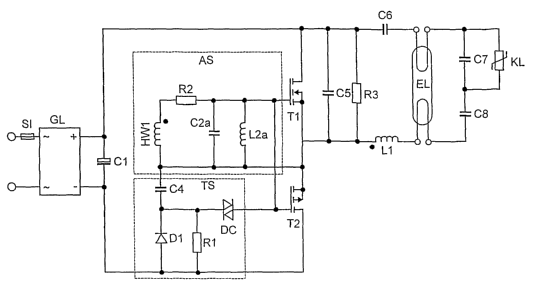
The circuit arrangement illustrated in figure 1 for operating a
low-pressure discharge lamp EL is known from EP 0 781 077 Bl.
In this case, it is a half-bridge arrangement with two
transistors T1 and T2, which are controlled by a common drive
circuit AS. This drive circuit comprises a secondary winding
HW1 on an inductor Ll, which limits the lamp current and
excites a parallel resonant circuit C2a, L2a via a resistor R2.
The AC voltage, which is applied to the control inputs of the
complementary half-bridge transistors by this parallel resonant
circuit, results in the two transistors Tl and T2 switching on
alternately, as a result of which the DC voltage present at the
capacitor Cl is converted in a known manner into a high-
frequency AC voltage for supplying the load circuit (comprising
C5, C6, C7, C8, KL, EL, R3 and L1).
The LC parallel resonant circuit comprising C2a and L2a is
therefore DC-connected to the auxiliary winding HW1 via the
resistor R2 for the purpose of injecting energy from the load
circuit.
The element denoted here by TS does not need to be described in
any more detail. It is a runup circuit which is used for
starting the self-oscillating oscillation.
CA 02610473 2007-11-30
PCT/DE2006/000932 - 7 -
05P06946
The operating frequency at which the resonant circuit is fed is
strongly dependent on the natural resonant frequency of the
resonant circuit comprising C2a and L2a. The component parts
C2a and L2a are therefore power-determining component parts
because the natural resonant frequency influences the current
applied to the lamp EL via the operating frequency of the
circuit arrangement.
According to the invention, the capacitance C2a or the
inductance L2a is now designed to be temperature-dependent. As
the temperature increases, in this case the capacitance or the
inductance should decrease and thus the natural resonant
frequency of the parallel resonant circuit should increase. As
a result, the operating frequency of the circuit arrangement
and therefore the AC resistance of the lamp inductor Ll
increases as the temperature increases. The currents in the
component parts of the circuit arrangement and in the lamp thus
become lower, and the thermal loading of the system is limited.
In the case of conventional components, the variation of the
capacitance or the inductance in the permissible temperature
range may possibly be too great. In order to ensure correct
functioning of the circuit arrangement, this being at all
temperatures, an embodiment in accordance with figure 2 is
proposed. In this case, only the capacitance is designed to be
temperature-dependent. The capacitance comprises two capacitors
C2 and C3, of which the capacitor C2 has a temperature-
independent value, which approximately corresponds to the
maximum value of the capacitance desired at a minimum
temperature. The second capacitor C3 should have a considerably
higher value than the capacitor C2 given a relatively low
temperature, with the result that the total capacitance of the
series circuit comprising C2 and C3 is substantially defined by
the size of C2. As the temperature increases, the capacitance
of C3 should become significantly lower, as a result of which
the total capacitance of the series circuit decreases. At a
CA 02610473 2007-11-30
PCT/DE2006/000932 - 8 -
05P06946
maximum temperature, the capacitance should reach a minimum
value.
The response of the capacitance of the series circuit
comprising C2 and C3 is illustrated in figure 4. This shows, by
way of example, the total capacitance of a parallel resonant
circuit as shown in figure 2, in which C2 = 3.3 nF and C3 =
100 nF at 100 Celsius. The capacitance of the capacitor C3 is
assumed to decrease linearly and up to approximately 100
Celsius (in the model these are only approximations) assumes a
value of likewise 3.3 nF. At 100 Celsius, the total
capacitance therefore decreases almost to half the value at 10
Celsius.
Figure 5 illustrates the dependence of the natural resonant
frequency of the parallel resonant circuit of the above-
mentioned type on the temperature of the capacitor C3.
In particular it can clearly be seen in figure 5 that the
temperature only has a notable influence on the resonant
frequency above approximately 50 to 60 Celsius. As the
temperature approaches 100 Celsius, where it is particularly
critical, the change in the resonant frequency is particularly
noticeable.
The current in the discharge lamp is therefore severely reduced
between 50 and 100 Celsius, with the result that further
heating of component parts cannot result.
As an alternative to the measure illustrated in figure 2 that
two capacitors are provided for implementing the capacitance
C2a, of which one is temperature-dependent, the inductance L2a
can also be designed in such a way that it comprises two
inductances L2 and L3 in series, as is illustrated in figure 3.
One of the inductors, L2, has a temperature-independent value,
which approximately corresponds to the minimum value desired at
CA 02610473 2007-11-30
PCT/DE2006/000932 - 9 -
05P06946
a maximum temperature. The second inductor L3 is intended to
have, at a low temperature, such a value at which the total
inductance of the series circuit comprising L2 and L3
corresponds to the value which is required for normal
temperatures. As the temperature increases, the inductance of
L3 should become significantly lower until it reaches a minimum
value at a maximum temperature.
The embodiments shown in figure 2 and figure 3 can also be
combined with one another, i.e, provision may also be made for
both the capacitance C2a and the inductance L2a to each
comprise temperature-dependent elements in series with
temperature-independent elements.
The use of the circuit from EP 0 781 077 Bl merely serves as an
example and is used for explaining what is meant by
power-determining component part. The circuit arrangement in
accordance with EP 0 530 603 Bl is substantially identical to
the circuit arrangement illustrated in figure 1 from EP 0
781 077 El, the inductor L2a being omitted in the drive
circuit. Instead of an LC parallel resonant circuit, there is
an RC element, whose low-pass properties have a similar
influence on the operating frequency. Correspondingly, with
this circuit the invention also provides for the capacitance
from the drive circuit to be designed to be temperature-
dependent. This can in particular also take place using two
capacitors which are connected in series, of which one is
strongly temperature-dependent and the other is temperature-
independent.
The power-determining component part within the meaning of the
invention is not understood as being any component part which
in a marginal way has an influence on the power, but component
parts which are suitable for noticeably influencing the power
consumption of the lamp given a temperature-dependent design in
CA 02610473 2007-11-30
PCT/DE2006/000932 - 10 -
05P06946
order to thus bring about a visible effect in relation to the
temperature control.