Note: Descriptions are shown in the official language in which they were submitted.
CA 02610743 2007-12-03
WO 2006/130654
PCT/US2006/021061
1
SEGREGATED CATALYZED METALLIC WIRE FILTER FOR DIESEL SOOT
FILTRATION
FIELD OF THE INVENTION
This invention relates to diesel engine exhaust gas treatment and more
particularly to the filtering of particulates from diesel engine exhaust gases
using a
catalyzed filter.
BACKGROUND OF THE INVENTION
Diesel engine exhaust is a heterogeneous mixture which contains not only
gaseous emissions such as carbon monoxide ("CO"), unburned hydrocarbons ("HC")
and nitrogen oxides ("NOx "), but also condensed phase materials (liquids and
solids)
which constitute the so-called particulates or particulate matter ("PM"). The
total
particulate matter ("TPM") emissions are comprised of three main components.
One
component is the solid, dry, solid carbonaceous fraction or soot. This dry
carbonaceous matter contributes to the visible soot emissions commonly
associated
with diesel exhaust. A second component of the TPM is the soluble organic
fraction
("SOF"). The soluble organic fraction is sometimes referred to as the volatile
organic
fraction ("VOF"), which terminology will be used herein. The VOF may exist in
diesel exhaust either as a vapor or as an aerosol (fine droplets of liquid
condensate)
depending on the temperature of the diesel exhaust, and are generally present
as
condensed liquids at the standard particulate collection temperature of 52 C
in diluted
exhaust, as prescribed by a standard measurement test, such as the U.S. Heavy
Duty
Transient Federal Test Procedure. These liquids arise from two sources: (1)
lubricating oil swept from the cylinder walls of the engine each time the
pistons go up
and down; and (2) unburned or partially burned diesel fuel.
The third component of the particulates is the so-called sulfate fraction.
Diesel
fuel contains sulfur, and even the low sulfur fuel available in the U.S. may
contain
0.005% sulfur. Upon combustion of the fuel in the engine, nearly all of the
sulfur is
oxidized to sulfur dioxide which exits with the exhaust in the gas phase.
However, a
small portion of the sulfur, perhaps 2-5%, is oxidized further to SO3, which
in turn
combines rapidly with water in the exhaust to form sulfuric acid which
collects as a
CA 02610743 2007-12-03
WO 2006/130654 PCT/US2006/021061
2
condensed phase with the particulates as an aerosol, or is adsorbed onto the
other
particulate components, and thereby adds to the mass of TPM.
Emissions from diesel engines have been under increasing scrutiny in recent
years and standards, especially for particulate emissions, have become
stricter. In
1994 the particulate emission standards in the U.S. for new engines allowed no
more
than a total of 0.1 grams per brake horse power hour (g/BHP-h). For diesel
engines in
buses operating in congested urban areas the particulate emissions standard
was even
stricter, 0.07 g/BHP-h TPM. Both of these standards were seen as significant
reductions relative to the prior particulate emission standard of 0.25 g/BHP-h
which
had been in effect since 1991. Starting in 1994, for the first time, engine
technology
developments alone were found to be incapable of meeting the new standards,
and for
some engines after treatment technology, for example, diesel oxidation
catalyst
(DOC) units, as discussed further below, were necessary.
The question of how best to reduce the levels of particulate matter expelled
to
the atmosphere in the exhaust gases of diesel engines is currently of
considerable
interest as stricter emission standards are constantly being legislated
through the next
decade. In this connection, it is desired to develop efficient and practical
devices for
removing substantial portions of particulates from the exhaust gases in diesel
engine
exhaust systems before permitting the exhaust gases to escape to the
atmosphere.
It is known in the art to provide diesel engines with an exhaust filter which
traps particulates from the exhaust gas stream during engine operation. The
filters are
generally made of porous, solid materials having a plurality of pores
extending
therethrough and having small cross-sectional size, such that the filter is
permeable to
the exhaust gases which flow through the filters and are capable of
restraining most or
all of the particulates from passing through the filter with the gas. The
restrained
particulates consist generally of carbonaceous particulates in the form of
soot particles
and reference herein and in the claims to "particulate" and "particulates"
means such
diesel engine-generated particles. As the mass of collected particulates
increases, the
flow rate of the exhaust gas through the filter is usually impeded, whereby an
increased back pressure is encountered within the filter and reduced engine
efficiency
results.
There is a desire in the art to more simply regenerate the particulate filter
by
continuous bum-off or incineration of the soot particles as they are trapped
in the
CA 02610743 2007-12-03
WO 2006/130654
PCT/US2006/021061
3
filter. However, experience has shown that in normal diesel engine operation,
the
temperature in the exhaust system varies substantially under different
conditions of
engine load and speed and that the temperatures in the filter hardly ever
reach the 510
C temperature level required to incinerate the trapped particulate.
In order to comply with the ever-increasing legislation both in the United
States and Europe to reduce the level of solid emissions from both on- and off-
highway diesel-powered vehicles, exhaust after-treatment, such as a variety of
soot
filter media, have been explored. The wallflow type ceramic honeycomb filter
is the
most widely employed filtration technology used in current systems for
industrial
applications. Wallflow filters provide an answer to the filtration
requirement, yet there
remains the residual problem of achieving a reliable and repeatable method of
cleaning the filter. This residual problem has been the source of extensive
engineering
research and development. Wallflow filter elements are particularly useful to
filter
particulate matter from diesel engine exhaust gases. Many references disclose
the use
of wallflow filters which can comprise catalysts on or in the filter to filter
and burn off
filtered particulate matter. A common ceramic wallflow filter construction is
a multi-
channel honeycomb structure having the ends of alternate channels on the
upstream
and downstream sides of the honeycomb structure plugged. This results in a
checkerboard-type pattern on either end. Channels plugged on the upstream or
inlet
end are open on the downstream or outlet end. This permits the gas to enter
the open
upstream channels, flow through the porous walls and exit through the channels
having open downstream ends. The gas pressure forces the gas through the
porous
structural walls into the channels closed at the upstream end and open at the
downstream end. Such structures are primarily disclosed to filter particles
out of the
exhaust gas stream.
It is desired to remove the particulate matter from the upstream sides of the
wallflow filters. One method is to provide a layer of catalyst on the wall to
catalyze
the ignition of the particulate matter during operation of the filter. There
are many
U.S. patents disclosing such wallflow structures.
A particularly useful particulate emission control filter directed for use for
diesel exhaust is presented in "3M Diesel Filters for Particulate Emission
Control,
Designers Guide" published by 3M Ceramic Materials Department, printed 1994
January and hereby incorporated by reference. There is described a ceramic
filter
CA 02610743 2007-12-03
WO 2006/130654 PCT/US2006/021061
4
comprising ceramic fiber specified to have 62% A1203, 24% Si02, and 14% B203.
The filter specification includes a white continuous fiber having a fiber
diameter of
10-12 microns with a fiber density of 2.7 grams per cubic centimeter. The
mechanical
properties of the fiber include a filament tensile strength of 1.72 GPA, a
filament
tensile modulus of elasticity of 138 GPA, and elongation of 1.2%. The
specified
thermal properties are continuous use temperature of 1204 C, short-term use
temperature at 1371 C, a lineal shrinkage at 1093 C of 1.25%, a melting
point of
1800 C, a thermal expansion co-efficient (25-500 C) of 3.0x10⁻⁶ AL/L C, and
a
specific heat of 1046.7 J/Kg K. The fiber is sold by the 3M Ceramic Materials
Department as NEXTELTm FIBER. The above specified properties are for
NEXTELTm 312 CERAMIC FIBER.
The NEXIELTM fibers are used to make diesel filters. A typical 3M diesel
filter cartridge has a cylindrical support and a continuous ceramic fiber
woven in a
diamond pattern on the support to form a ceramic fiber winding, see U.S.
5,551,971,
Figure 1. The cylindrical support is an electric resistant heating element
that contains
openings. The area of the openings can be used to control the heat input along
the
support. Where less heat is desired, the support can have larger openings or
more
openings at a given location. The distribution of openings can be varied with
the most
open area toward the center of the support. The cylindrical support has an
open end
and a closed end. The filter is useful to filter particulate matter from
diesel engine
exhaust. During engine operation gas laden with particulate matter can pass
through
the outer circumferential surface of the ceramic fiber windings through the
open areas
of the cylindrical support and out through the open end. Alternatively and
preferably,
the filter cartridge can be operated in reverse. Particle laden gases can be
fed into
open end, pass through the open areas of cylindrical support and then through
ceramic
fiber windings depositing its particles in the ceramic fiber windings.
During heating to regenerate the filter, an oxygen laden gas, preferably air,
is
fed into open end. Electric energy is input to heat the cylindrical support
which acts as
a heating element or heater. The cylindrical heating element heats the ceramic
fiber
windings to a temperature sufficient to oxidize particulate matter trapped
thereon.
The filter cartridge is used in a diesel engine exhaust system. Typically, a
plurality of filters are assembled within a canister. The number of filter
cartridges
CA 02610743 2007-12-03
WO 2006/130654
PCT/US2006/021061
assembled in a canister is sized to the exhaust flow rates and anticipated
regeneration
intervals.
While a variety of soot filters are known in the art, improvements are
continually desired not only in the regeneration of such filters, but for the
ease of
5 manufacture, retrofitting, and replacement of such filters. Improvements
are further
desired in maintaining gas flow through the filters even if soot accumulation
exceeds
the soot-burning rate of the filtering media so as to keep the vehicle running
until
cleaning can occur.
SUMMARY OF THE INVENTION
A diesel soot filter is provided comprising a plurality of parallel channels
that
are composed of a metallic mesh to trap soot particles as the diesel exhaust
gas passes
through the channels. The filtering channels can be arranged such as in a
canister
such that smaller by-pass gas channels are formed between the filtering
channels. The
by-pass channels allow the exhaust gas to pass therethrough in the event that
soot
accumulation in the main filtering channels exceeds the burning rate of the
accumulated soot. The reduced gas flow through the by-pass channels reduces
the
back pressure and keeps the vehicle running until a favorable regeneration of
the filter
is achieved. The wire mesh can be removed from the channels and replaced with
new
metal mesh, and/or the channels containing the metal mesh may also be removed
and
replaced if needed to renew soot removal.
BRIEF DESCRIPTION OF THE DRAWINGS
Figure 1 is a longitudinal cross-sectional view of a canister holding the soot
filter channels of this invention and taken along line 1-1 of Figure 2.
Figure 2 is a transverse sectional view of the canister and soot filter device
of
the present invention taken along line 2-2 of Figure 1.
Figure 3 is a perspective view of a soot filter channel of this invention.
Figure 4 is a plan view of one of the end plates which can be used to hold the
soot filter channels in place.
CA 02610743 2007-12-03
WO 2006/130654 PCT/US2006/021061
6
DETAILED DESCRIPTION OF THE INVENTION
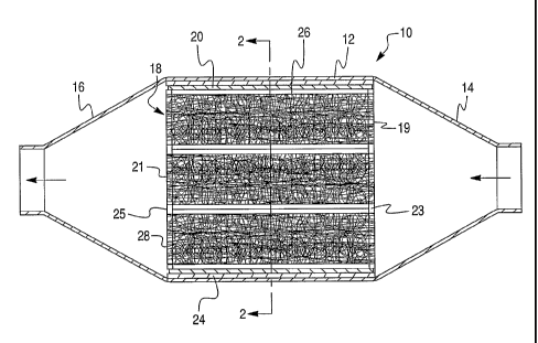
In Fig. 1, the filtering element of this invention is shown installed as a
diesel
particulate trap 10 which has a canister of rectangular tubular casing 12, a
pyramidal
exhaust inlet 14, and a pyramidal exhaust outlet 16. As installed, a plurality
of hollow
channels 18 extend in the axial or longitudinal direction of the filtering
element which
is also the primary direction of the flow of exhaust through the diesel
particulate trap.
The metal sleeve 20 of the filtering element has been sealed to the casing 12
by an
intumescent mat 24 that expands when exposed to the heat of the first use of
the diesel
particulate trap. Any such mat should be selected to withstand temperatures
encountered in use, especially temperatures at which the filtering element is
to be
regenerated. A particularly useful intumescent mat is provided by a heat-
expandable
vermiculite mat.
The channel walls which form each of channels 18 are impervious metal sheet
in circular, square, trapezoid, rectangular, etc., designs shown in Figs. 1
and 2 as
cylindrical channels 18 having a circular cross-section and open at each end
19 and
21. The inside diameter of channel 18, regardless of shape, will be at least
0.5 in,
preferably at least about 1.0 inch wide. A plurality of channels 18 are placed
within
enclosed area 26 of casing 12. End plates 23 and 25 on opposite ends of area
26 and
welded or otherwise attached to metal sleeve 20 support the opposing ends of
channels 18. End plates 23 and 25 can include openings through which the ends
of
channels 18 are supported. The channels 18 may be permanently fixed to end
plates
23 and 25 or temporarily fit so that such channels can be replaced due to
wear. Thus,
the outside diameters or perimeters of channels 18 can be such as to be
pressure fit
within the openings 32 of the end plates 23 and 25, see Fig. 4, or otherwise
removably
attached thereto such by bolts, screws, etc., so as to remain in place during
use. Upon
wear, the channels 18 can be removed from the respective openings 32 in the
end
plates 23 and 25 and slid from the interior of enclosed area 26 for repair
and/or
replacement.
Within the interior of each channel 18 is placed a metal mesh filtering
element
28 which is capable of trapping the soot particles contained within the diesel
exhaust.
The metal mesh can be of various types and configurations so long as the mesh
filtering element 28 allows for gas flow therethrough, but forms a barrier for
soot
particles. Woven metal mesh such as of steel wool type, non-woven wire mesh in
CA 02610743 2007-12-03
WO 2006/130654 PCT/US2006/021061
7
which individual wires are spot soldered or the like with other wires to form
a single
mesh unit, braided wire mesh in which a plurality of wire strands are twisted
together
to form a mesh capable of the desired removal of soot from a passing gas
stream can
be used. The metal mesh filtering element 28 is preferably placed as a single
mass
within the interior of each channel 18 so as to substantially completely fill
the channel
interior. More than one piece of metal mesh can be used if more convenient to
fill the
channel interiors. The metal mesh filtering element 28 can be readily
removable from
within each channel 18 so as to be easily substituted with repaired,
regenerated, or a
new mesh element to maintain optimum filtering capability. The metal mesh
filtering
element 28 can be pressure fit within each channel interior so as to remain in
place
during operation. Alternatively, or in addition to pressure fitting, each open
end 19
and 21 of channel 18 may contain one or more cross pieces or mesh (not shown)
to
keep the metal mesh filtering element 28 in place within the interior of
channels 18.
It is well known in the art of diesel soot filters to burn off the soot
particles
from the filter so as to regenerate the filter and again improve its capacity
to filter the
soot particles from the exhaust gas. Unfortunately, the temperature generated
by the
diesel engine and imparted to the exhaust gas is not high enough to initiate
ignition
and burning of the soot particles. Accordingly, oxidation catalysts have been
incorporated onto the filtering element so as to lower the ignition
temperature of the
soot particles and allow the particles to be burned and the filter element
regenerated
either on a continuous or alternating process between filtering and
regenerating. In
accordance with the present invention, the metal mesh elements 28 of this
invention
can be coated with the oxidation catalysts well known in the art to initiate
the ignition
of the soot particles from the diesel exhaust gas that are trapped within the
filtering
element. The types of catalysts and the methods of applying the catalysts to
the metal
mesh filtering element 28 are more fully explained below. In addition to
coating the
wire mesh filtering element 28, it is also possible to coat the interior of
the channels
18 with an oxidation catalyst to initiate ignition of any soot particles
attached to the
interior walls and/or initiate oxidation of gaseous contaminants within the
exhaust gas
itself, such as CO, HC, and NOx. The catalyst on the metal mesh filtering
element 28
may be the same or different than the catalyst that is coated on the interior
walls of
channels 18. Further, any wire elements used to maintain the filtering
elements 28 in
place within channels 18, such as any mesh or the like, provided in openings
19 and
CA 02610743 2007-12-03
WO 2006/130654 PCT/US2006/021061
8
21 can also be provided with a catalytic coating. Still further, it may be
possible to
provide an oxidation catalyst on at least a portion of the exterior of the
channels 18, in
particular, those areas of the channels which are in contact with the
interstitial voids
30, which are formed between the channels 18 as the channels are stacked
within
enclosed area 26 of casing 12. Thus, exhaust gas that passes through the
interstitial
voids 30 can be treated so as to initiate oxidation of the exhaust gas
contaminants.
The filter device 10 of this invention will be placed in an exhaust stream
from
a diesel engine. A diesel oxidation catalyst (DOC) may or may not be placed in
front
of the filtering device 10 dependent upon the application. An exhaust gas from
the
diesel engine containing HC, CO, NOx, and particulate matter passes through
the
filter device 10 and, in particular, channels 18. Due to the impaction of the
soot
particles on the catalyzed wire mesh element 28, the soot particles are
collected and
burnt under suitable exhaust regeneration conditions. If the application is
such that
the soot accumulation rate on filter element 28 exceeds the burning rate of
the soot
particles, exhaust gas flow from the engine will be forced and diverted
through the
interstices 30 between the stacked channels 18 within casing 12. The
interstitial voids
30 are initially sized to permit only minor flow during most diesel engine
operating
conditions since the back pressure in the interstities 30 is higher than the
back
pressure through mesh filtering element 28. Typically the interstitial void
volume
within enclosed area 26 of casing 12 will comprise less than 25% of the volume
of
enclosed area 26. Gas flow through the interstitial void volume can be
controlled or
limited by use of orifice openings 34 in the endplates such as shown for
endplate 23 in
Fig.4. When the soot accumulates and starts to block the pores of the metal
mesh
filtering element 28 and the back pressure rises, the interstitial or bypass
voids 30 still
enable exhaust gas flow and allow the diesel engine to continue operation. In
this
way the vehicle will not stall due to a totally restricted flow path of the
exhaust gas.
The density of the wire mesh (wire diameter and the amount of wire weaved into
the
matrix) determines the back pressure.
The metal mesh can be made of any relatively high temperature alloy,
including most stainless steels, Fecralloy, Hastalloy, etc.
In a preferred embodiment of the invention, the metal mesh is pretreated prior
to deposition of the catalyst composition to improve the adherence of
composition on
the substrate. Pretreatment of the substrate can be conducted by applying a
metal
CA 02610743 2013-02-07
9
anchor layer to the substrate by known thermal spraying techniques before the
catalyst
slurry is applied. These techniques include plasma spraying, single wire
spraying,
high velocity oxy-fuel spraying, combustion wire and/or powder spraying,
electric arc
spraying etc. Preferably the metal anchor layer is applied by electric arc
spraying.
Electric arc spraying, e.g., twin wire arc spraying, of a metal (which term,
as
used herein, includes mixtures of metals, including without limitation, metal
alloys,
pseudoalloys, and other intermetallic combinations) onto a metal forarninous
substrate
yields a structure having superior utility as a substrate for catalytic
materials in the
field of catalyst members. Twin wire arc spraying (encompassed herein by the
term
"wire arc spraying" and by the broader term "electric arc spraying") is a
known
process, disclosed in United States Patent No. 4,027,367 which is incorporated
herein
by reference. Briefly described, in the twin wire arc spray process, two
feedstock
wires act as two consumable electrodes. These wires are insulated from each
other as
they are fed to the spray nozzle of a spray gun in a fashion similar to wire
flame guns.
The wires meet in the center of a gas stream generated in the nozzle. An
electric arc is
initiated between the wires, and the current flowing through the wires causes
their tips =
to melt. A compressed atomizing gas, usually air, is directed through the
nozzle and
across the arc zone, shearing off the molten droplets to form a spray that is
propelled
onto the substrate. Only metal wire feedstock can be used in an arc spray
system
because the feedstock must be conductive. The high particle temperatures
created by
the spray gun produce minute weld zones at the impact point on a metallic
substrate.
As a result, such electric arc spray coatings (sometimes referred to herein as
"anchor
layers") maintain a strong adhesive bond with the substrate.
Operating parameters for wire arc spraying for forming anchor layer on
foraminous substrates are disclosed in copending United States Patent
Application
No. 09/301,626, filed April 29, 1999 (the '626 application), now U.S.
Publication No.
2002/0128151, published September 12, 2002.
Anchor layers of a variety of compositions can be deposited on a substrate by
utilizing, without limitation, feedstocks of the following metals and metal
mixtures:
Ni, Ni/A1, Ni/Cr, Ni/Cr/Al/Y, Co/Cr, Co/Cr/A1/Y, Co/Ni/Cr/AI/Y, Fe/A1, Fe/Cr,
Fe/Cr/A1, Fe/Cr/AIN, Fe/Ni/AI, Fe/Ni/Cr, 300 and 400 series stainless steels,
and,
optionally, mixtures of one or more thereof. One specific example of a metal
useful
CA 02610743 2007-12-03
WO 2006/130654 PCT/US2006/021061
for wire arc spraying onto a substrate in accordance with the '626 application
is a
nickel/aluminum alloy that generally contains at least about 90% nickel and
from
about 3% to 10% aluminum, preferably from about 4% to 6% aluminum by weight.
Such an alloy may contain minor proportions of other metals referred to herein
as
5 "impurities" totaling not more than about 2% of the alloy. A preferred
specific
feedstock alloy comprises about 95% nickel and 5% aluminum and may have a
melting point of about 2642 F. Some such impurities may be included in the
alloy
for various purposes, e.g., as processing aids to facilitate the wire arc
spraying process
or the formation of the anchor layer, or to provide the anchor layer with
favorable
10 properties.
Electric arc spraying a metal onto a metal substrate yields a superior
substrate
for catalytic materials relative to substrates having metal anchor layers
applied thereto
by other methods. Catalytic materials have been seen to adhere better to a
substrate
comprising an electric arc sprayed anchor layers than to a substrate without
an
intermediate layer applied thereto and even better than to a substrate having
a metal
layer deposited thereon by plasma spraying. Catalytic materials disposed on
metal
substrates, without intermediate layers between the substrate and the
catalytic
material, often did not adhere sufficiently well to the substrate to provide a
commercially acceptable product. Metal substrates having an intermediate layer
applied by other thermal spraying techniques typically suffer the same
drawbacks.
For example, a metal substrate having a metal intermediate layer that was
plasma-
sprayed thereon and having a catalytic material applied to the intermediate
layer failed
to retain the catalytic material, which flaked off upon routine handling,
apparently due
to a failure of the intermediate layer to bond with the substrate. The
catalytic material
on other substrates was seen to spall off upon normal use, apparently as a
result of
being subjected to a high gas flow rate, to thermal cycling, to the eroding
contact of
high temperature steam and other components of the exhaust gas stream,
vibrations,
etc. Application of the intermediate layer by electric arc spraying therefore
improves
the durability of catalyst members comprising catalytic materials carried on
foraminous substrates by improving their durability.
The metal mesh filter elements of this invention (also referred to herein as
foraminous substrates) useful for fouling the filtering elements include those
metallic
substrates which are able to accommodate a high flow rate, are lightweight and
have a
CA 02610743 2007-12-03
WO 2006/130654 PCT/US2006/021061
11
low thermal mass. The woven, non-woven, and braided wire mesh of this
invention
as filter element 28 are suitable for application of a metal anchor layer.
A suitable catalytic material for use on a foraminous substrate can be
prepared
by dispersing a compound and/or complex of any catalytically active component,
e.g.,
one or more platinum group metal compounds or complexes, onto relatively inert
bulk
support material. As used herein, the term "compound", as in "platinum group
metal
compound" means any salt, complex, or the like of a catalytically active
component
(or "catalytic component") which, upon calcination or upon use of the
catalyst,
decomposes or otherwise converts to a catalytically active form, which is
often, but
not necessarily, an oxide. The compounds or complexes of one or more catalytic
compounds may be dissolved or suspended in any liquid which will wet or
impregnate the support material, which does not adversely react with other
components of the catalytic material and which is capable of being removed
from the
catalyst by volatilization or decomposition upon heating and/or the
application of a
vacuum. Generally, both from the point of view of economics and environmental
aspects, aqueous solutions of soluble compounds or complexes are preferred.
For
example, suitable water-soluble platinum group metal compounds are
chloroplatinic
acid, amine solubilized platinum hydroxide, rhodium chloride, rhodium nitrate,
hexamine rhodium chloride, palladium nitrate or palladium chloride, etc. The
compound-containing liquid is impregnated into the pores of the bulk support
particles of the catalyst, and the impregnated material is dried and
preferably calcined
to remove the liquid and bind the platinum group metal into the support
material. In
some cases, the completion of removal of the liquid (which may be present as,
e.g.,
water of crystallization) may not occur until the catalyst is placed into use
and
subjected to the high temperature exhaust gas. During the calcination step, or
at least
during the initial phase of use of the catalyst, such compounds are converted
into a
catalytically active form of the platinum group metal or a compound thereof.
An
analogous approach can be taken to incorporate the other components into the
catalytic material. Optionally, the inert support materials may be omitted and
the
catalytic material may consist essentially of the catalytic component
deposited
directly on the sprayed foraminous substrate by conventional methods.
Preferred platinum group metal components for use in the articles of the
invention include platinum, palladium, rhodium, ruthenium and iridium
components.
CA 02610743 2007-12-03
WO 2006/130654 PCT/US2006/021061
12
Platinum, palladium and rhodium components are particularly preferred. When
deposited on a foraminous substrate (e.g., metal screen) such components are
generally deposited at a concentration of from 0.001 to 0.01 g/in2 for typical
utility
engine applications.
Suitable support materials for the catalytic component include alumina,
silica,
titania, silica-alumina, alumino-silicates, aluminum-zirconium oxide, aluminum-
chromium oxide, etc. Such materials are preferably used in their high surface
area
forms. For example, gamma-alumina is preferred over alpha-alumina. It is known
to
stabilize high surface area support materials by impregnating the material
with a
stabilizer species. For example, gamma-alumina can be stabilized against
thermal
degradation by impregnating the material with a solution of a cerium compound
and
then calcining the impregnated material to remove the solvent and convert the
cerium
compound to a cerium oxide. The stabilizing species may be present in an
amount of
from about, e.g., 5 percent by weight of the support material. The catalytic
materials
are typically used in particulate form with particles in the micron-sized
range, e.g., 10
to 20 microns in diameter, so that they can be formed into a slurry and coated
onto a
substrate.
A typical catalytic material for use on a filter member for diesel engine
exhaust comprises platinum, palladium and rhodium dispersed on an alumina and
further comprises oxides of neodymium, strontium, lanthanum, barium and
zirconium. Some suitable catalysts are described in United States Patent
Application
Serial. No. 08/761,544 filed December 6, 1996, the disclosure of which is
incorporated herein by reference. In one embodiment described therein, a
catalytic
material comprises a first refractory component and at least one first
platinum group
component, preferably a first palladium component and optionally, at least one
first
platinum group metal component other than palladium, an oxygen storage
component
which is preferably in intimate contact with the platinum group metal
component in
the first layer. An oxygen storage component (OSC") effectively absorbs excess
oxygen during periods of lean engine operation and releases oxygen during
periods
where localized concatenations of fuel produce a rich environment as seen in
light-off
of the catalyst after prolonged idle condition. Bulk ceria is known for use as
a OSC,
but other rare earth oxides may be used as well. In addition, as indicated
above, a co-
formed rare earth oxide-zirconia may be employed as a OSC. The co-formed rare
CA 02610743 2007-12-03
WO 2006/130654 PCT/US2006/021061
13
earth oxide-zirconia may be made by any suitable technique such as co-
precipitation,
co-gelling or the like. One suitable technique for making a co-formed ceria-
zirconia
material is illustrated in the article by Luccini, E., Mariani, S., and
Sbaizero, 0.
(1989) "Preparation of Zirconia Cerium Carbonate in Water With Urea" Int. J.
of
Materials and Product Technology, vol. 4, no. 2, pp. 167-175, the disclosure
of which
is incorporated herein by reference. As disclosed starting at page 169 of the
article, a
dilute (0.1 M) distilled water solution of zirconyl chloride and cerium
nitrate in
proportions to promote a final product of Zr02-10 mol % Ce02 is prepared with
ammonium nitrate as a buffer, to control pH. The solution was boiled with
constant
stirring for two hours and complete precipitation was attained with the pH not
exceeding 6.5 at any stage.
Any suitable technique for preparing the co-formed rare earth oxide-zirconia
may be employed, provided that the resultant product contains the rare earth
oxide
dispersed substantially throughout the entire zirconia matrix in the finished
product,
and not merely on the surface of the zirconia particles or only within a
surface layer,
thereby leaving a substantial core of the zirconia matrix without rare earth
oxide
dispersed therein. Thus, co-precipitated zirconium and cerium (or one other
rare earth
metal) salts may include chlorides, sulfates, nitrates, acetates, etc. The co-
precipitates
may, after washing, be spray dried or freeze dried to remove water and then
calcined
in air at about 500 C. to form the co-formed rare earth oxide-zirconia
support. The
catalytic materials of aforesaid application serial. No. 08/761,544 may also
include a
first zirconium component, at least one first alkaline earth metal component,
and at
least one first rare earth metal component selected from the group consisting
of
lanthanum metal components and neodymium metal components. The catalytic
material may also contain at least one alkaline earth metal component and at
least one
rare earth component and, optionally, at least one additional platinum group
metal
component preferably selected from the group consisting of platinum, rhodium,
ruthenium, and iridium components with preferred additional first layer
platinum
group metal components being selected from the group consisting of platinum
and
rhodium and mixtures thereof
A variety of deposition methods are known in the art for depositing catalytic
material on a foraminous substrate. These methods of applying the catalytic
CA 02610743 2007-12-03
WO 2006/130654 PCT/US2006/021061
14
component onto the substrate constitute a separate step in the manufacturing
process
relative to the application of any anchor layer (if applied) to the substrate.
Methods for depositing catalytic material on the foraminous substrate include,
for example, disposing the catalytic material in a liquid vehicle to form a
slurry and
wetting the foraminous substrate with the slurry by dipping the substrate into
the
slurry, spraying the slurry onto the substrate, etc. Alternatively, the
catalytic material
may be dissolved in a solvent and the solvent may then be wetted onto the
surface of
the foraminous substrate and thereafter removed to leave the catalytic
material, or a
precursor thereof, on the foraminous substrate. The removal procedure may
entail
heating the wetted substrate and/or subjecting the wetted substrate to a
vacuum to
remove the solvent via evaporation.
Example 1 Preparation of a Catalyst Composition Containing Platinum and
Palladium
in a 4:1 Ratio
First platinum and palladium compounds were dispersed on high surface area
gamma alumina and 5% lanthanum modified alumina supports. Into 2104.5 g of
gamma alumina (97% solids) and 2041 g of 5% lanthanum stabilized alumina was
added an aqueous solution containing 133.9 g of Pt as a 16% amine solubilized
platinum hydroxide diluted with 709 g of deionized water with mixing. After
mixing
for additional 20 minutes a Pd solution was added containing 33.5 g Pd as a
19%
palladium nitrate solution diluted with 700 g of deionized water. This was
mixed an
additional 20 minutes to ensure the powder was uniformly contacted with the
precious
metal solution.
The resulting precious metal support mixture from above was contacted with
6189 g of deionized water, 433.9 g of 90 acetic acid and 18 g of octanol in a
dispersion tank. This mixture was fed into a continuous mill and ground until
> 90%
of the material had a particle diameter of less than 5 microns. A Ce/Zr
composite
oxide was added with an additional 120 g of acetic acid and the resulting
slurry was
further ground until the overall particle size was 90% < 1 micron. In a
dispersion tank
583.3 g of zirconyl acetate solution was added to the slurry and mixed
vigorously.
The final pH of the slurry was in the range of 4.0-4.8.
CA 02610743 2013-02-07
Example 2 - Preparation of Wire Mesh Foraminous Catalytic Substrate
To prepare an article having the design as shown in Figure 1, a stainless
steel
wool mesh was wire arc spray-coated with a nickel-altuninide alloy as
described in
Example 1 of the aforesaid '626 application. The steel wool mesh was then
coated
5 with the coating slurry described above (Example 1) at a washcoat
loading of 0.05 to
0.1 g/in2. The mesh was then fitted into a cylindrical channel having an
inside
diameter of 1.25 in.
While this invention has been described with an emphasis upon preferred
embodiments, it will be obvious to those of ordinary skill in the art that
variations in
10 the preferred devices and methods may be used and that it is intended that
the
invention may be practiced otherwise than as specifically described herein.
Accordingly, this invention includes all modifications encompassed within the
scope of the invention as defined by the claims that follow.
=