Note: Descriptions are shown in the official language in which they were submitted.
CA 02610806 2007-12-03
WO 2006/128285
PCT/CA2006/000881
A SYSTEM FOR THE CONVERSION OF CARBONACEOUS FEEDSTOCKS
TO A GAS OF A SPECIFIED COMPOSffION
FIELD OF THE INVENTION
This invention relates to the gasification of carbonaceous feedstocks, and in
particular
to a process and apparatus for the conversion of carbonaceous feedstocks to a
gas
having a specified composition.
BACKGROUND OF THE INVENTION
Gasification is a process that enables the production of a combustible or
synthetic gas
(e.g., H2, CO, CO2, CH4) from carbon-based feedstock, referred to as
carbonaceous
feedstock. The gas can be used to generate electricity or as a basic raw
material to
produce chemicals and liquid fuels. This process enables the production of a
gas that
can be used for generation of electricity or as primary building blocks for
manufacturers of chemicals and transportation fuels.
In particular, the gas can be used, for: the combustion in a boiler for the
production of
steam for internal processing and/or other external purposes; for the
generation of
electricity through a steam turbine; the combustion directly in a gas turbine
or a gas
engine for the production of electricity; fuel cells; the production of
methanol and
other liquid fuels; as a further feedstock for the production of chemicals
such as
plastics and fertilizers; the extraction of both hydrogen and carbon monoxide
as
discrete industrial fuel gases; and other industrial heat requirements as
required.
As useful feedstocks for the gasification process can be any carbonaceous
material,
the types of feedstock can range broadly. Useful feedstocks can include, but
are not
limited to, any waste materials, coal, petroleum coke, heavy oils, biomass and
agricultural wastes.
Generally, a gasification process consists of feeding carbon-containing
materials into
a heated chamber (the gasifier) along with a controlled and limited amount of
oxygen
and steam. At the high operating temperature created by conditions in the
gasifier,
1
CA 02610806 2007-12-03
WO 2006/128285
PCT/CA2006/000881
chemical bonds are broken by thermal energy and by partial oxidation, and
inorganic
mineral matter is fused or vitrified to form a molten glass-like substance
called slag.
Gasification (the complete conversion of carbonaceous feedstock to off-gas and
then
to syngas) can proceed at high temperature or low temperature, high pressure
or low
pressure and in one step or where the stages are separated to some degree
under
conditions (temperature, process additives) in a manner that certain reactions
are
favored over another. It can occur in one chamber, multiple regions within one
chamber or multiple chambers. As the feedstock proceeds through a gasification
reactor, physical, chemical, and thermal processes may occur sequentially or
simultaneously, depending on the reactor design and the composition of the
feedstock.
Drying occurs as the feedstock is heated and its temperature increases, water
is the
first constituent to evolve.
As the temperature of the dry feedstock increases, pyrolysis takes place.
During
pyrolysis the feedstock is thermally decomposed to release tars, phenols, and
light
volatile hydrocarbon gases while the feedstock is converted to char. Depending
on
the origin of the feedstock, the volatiles may include H20, H2, N2, 02, CO2.
CO, CH,,
H2S, NH3, C2H6 and very low levels of unsaturated hydrocarbons such as
acetylenes,
olefins, aromatics and tars. Once a carbonaceous material is converted to a
gaseous
state, undesirable substances such as sulfur compounds and ash may be removed
from
the gas.
Char comprises the residual solids consisting of organic and inorganic
materials.
After pyrolysis, the char has a higher concentration of carbon than the dry
feedstock
and may serve as a source of activated carbon.
Gasification products are the result of chemical reactions between carbon in
the char
and steam, CO2, and H2 in the vessel as well as the chemical reactions between
the
resulting gases. The gasification reaction is driven by heat (pyrolysis). This
can be
fueled by adding electricity or fossil fuels (eg. propane) to heat the
reaction chamber
or adding air as a reactant to drive the exothermic gasification reaction,
which
provides heat to the reaction. Some gasification processes also use indirect
heating,
avoiding combustion of the feed material in the gasification reactor and
avoiding the
2
CA 02610806 2007-12-03
WO 2006/128285
PCT/CA2006/000881
dilution of the product gas with nitrogen and excess CO2.
The means of accomplishing a gasification process vary in many ways, but rely
on
four key engineering factors: the atmosphere (level of oxygen or air or steam
content)
in the reactor; the design of the reactor; the internal and external heating
means; and
the operating temperature for the process. The products of include hydrocarbon
gases
(also called syngas), hydrocarbon liquids (oils) and char (carbon black and
ash).
Some gasification systems employ plasma technology. Plasma is a fourth state
of
matter: an ionized gas resulting, e.g., from electric discharges. The plasma
torch heats
the gas molecules to such a high temperature that the molecules disassociate
into their
constituent atoms. Process heat is recovered from the hot stream of atoms
leaving the
plasma generator and the temperature of the stream of atoms is lowered to a
point
where some of the atoms begin to recombine. Since the input gases are
stoichiometrically deficient in oxygen, there is sufficient oxygen to produce
a
substantial quantity of carbon monoxide but insufficient oxygen to produce a
substantial quantity of carbon dioxide.
The very high temperatures (3000 to 7000 C) achievable with plasma arc torches
enable a gasification process where virtually any input feedstock including
waste in
as-received condition, including liquids, gases, and solids in any form or
combination
can be accommodated. Feedstock can range from bulky municipal solid waste
(MSW) such as household appliances, tires, bedsprings to waste materials such
as
low-level radioactive waste.
The plasma torches (technology) can be positioned to make all the reactions
happen
simultaneously, or can be positioned within the reaction vessel to make them
happen
sequentially. In either configuration, the temperature of the pyrolysis
process is
elevated due to inclusion of plasma torches (technology) in the reactor.
The means of accomplishing a gasification process vary in many ways, but rely
on
four key engineering factors: the atmosphere (level of oxygen, air or steam
content) in
the reactor; the design of the reactor; the design of the heating system; and
the
operating temperature for the process. Factors that affect the quality of the
product
3
CA 02610806 2007-12-03
WO 2006/128285
PCT/CA2006/000881
gas include: feedstock composition, preparation and particle size; reactor
heating rate;
residence time; the plant configuration including whether it employs a dry or
slurry
feed system, the feedstock-reactant flow geometry, the design of the dry ash
or slag
mineral removal system; whether it uses a direct or indirect heat generation
and
transfer method; and the syngas cleanup system.
These factors have been taken into account in the design of various different
systems,
which have been proposed for using plasma arc generators to convert waste into
electricity in an energy efficient manner. These systems are described, for
example,
in U.S. Patent Nos. 6,686,556, 6,630,113, 6,380,507; 6,215,678, 5,666,891,
5,798,497, 5,756,957, and U.S. Patent Application Nos. 2004/0251241,
2002/0144981.
There are also a number of patents relating to different technologies for the
gasification of coal for the production of synthesis gases for use in various
applications, including U.S. patent Nos. 4,141,694; 4,181,504; 4,208,191;
4,410,336;
4,472,172; 4,606,799;. 5,331,906; 5,486,269, and 6,200,430.
The gas produced during the gasification of carbonaceous feedstock is usually
very
hot and dirty, and requires further treatment to convert it into a useable
product. For
example, wet scrubbers and dry filtration systems are often used to remove
particulate
matter and acid gases from the gas produced during gasification. A number of
gasification systems have been developed which include systems to treat the
gas
produced during the gasification process.
U.S. Patent No. 6,810,821 describes an apparatus and method for treating the
gas
byproduct of a waste treatment system using a plasma torch which employs a
nitrogen-free working gas. U.S. Patent No. 5,785,923 describes an apparatus
for
continuous feed material melting which includes an off-gas receiving chamber
having
an off-gas heater, such as a plasma torch, for destroying the volatile
material.
This background information is provided for the purpose of making known
information believed by the applicant to be of possible relevance to the
present
4
CA 02610806 2007-12-03
WO 2006/128285
PCT/CA2006/000881
invention. No admission is necessarily intended, nor should be construed, that
any of
the preceding information constitutes prior art against the present invention.
SUMMARY OF THE INVENTION
An object of the present invention is to provide a system for the conversion
of a
carbonaceous feedstock to a gas of a specified composition, comprising: a
gasification
reaction vessel comprising: one or more processing zones, one or more plasma
heat
sources, one or more carbonaceous feedstock input means for adding the
carbonaceous feedstock to the gasification reaction vessel at an adjustable
carbonaceous feedstock feed rate one or more process additive input means for
adding
process additives to thc gasification reaction vessel at an adjustable process
additive
feed rate, one or more carbon-rich material additive input means for adding
carbon-
rich material additives to the gasification reaction vessel at an adjustable
carbon-rich
material additives feed rate, and one or more outlets for the output gas, a
solid residue
handling subsystem; a gas quality conditioning subsystem; and an integrated
control
system comprising: system monitoring means for measuring one or more system
parameters to generate data, computing means for collecting and analyzing the
data
generated by the system monitoring means, and output means to send appropriate
signals to effect change in one or more system regulators located throughout
the
system, wherein the control system monitors the one or more system parameters
and
sends signals to the appropriate system regulators to effect change in the one
or more
system regulators and thereby produce a product gas of a specified
composition.
BRIEF DESCRIPTION OF THE DRAWINGS
These and other features of the invention will become more apparent in the
following
detailed description in which reference is made to the appended drawings.
Figures 1 to 3 are schematic diagrams depicting a system for the conversion of
carbonaceous feedstocks to a gas of a specified composition in accordance with
various exemplary embodiments of the present invention.
CA 02610806 2007-12-03
WO 2006/128285
PCT/CA2006/000881
Figures 4 to 9 are schematic diagrams depicting various downstream
applications for
the system of Figures 1 to 3.
Figure 10 is a flow diagram depicting monitoring and regulating information
flow
between the system of Figures 1 to 9 and an integrated system control
subsystem
operatively coupled thereto.
Figure 11 is a schematic diagram depicting the integrated system control
subsystem
of Figure 10.
Figure 12 is a schematic diagram depicting exemplary monitoring and regulating
signals respectively received from and transmitted to the system of Figures 1
to 9 by
the integrated system control subsystem of Figure 10.
Figure 13 is a schematic diagram depicting exemplary monitoring and regulating
access points of the integrated system control subsystem of Figure 10 to
various
devices, modules and subsystems of the system of Figures 1 to 9.
Figures 14 and 15 are schematic diagrams depicting an exemplary embodiment of
the integrated system control subsystem of Figures 10 to 13 for controlling
inputs to a
plasma gasification vessel of the system of Figures 1 to 9.
Figures 16 to 20 are schematic diagrams depicting various plasma gasification
vessels for use with the system of Figures 1 to 9.
Figures 21 to 23 are schematic diagrams depicting exemplary heat recovery
subsystem for use with the system of Figures 1 to 9.
Figure 24 is a schematic diagram depicting in greater detail, a gas-to-gas
heat
exchanger of Figure 23.
Figure 25 is a schematic diagram depicting in greater detail, a heat recovery
steam
generator of Figure 23.
6
CA 02610806 2007-12-03
WO 2006/128285
PCT/CA2006/000881
Figure 26 is a schematic diagram depicting an optional steam/water treatment
subsystem for treating a steam/water output from the heat recovery steam
generation
system of Figures 1 to 9, and particularly of Figure 1.
Figure 27 is a schematic diagram depicting an embodiment of a gas quality
conditioning Suit for use with the system of Figures 1 to 9.
Figure 28 is a schematic diagram depicting various data inputs and outputs of
a
plasma gasification process simulation and system parameter optimization and
modeling means, optionally used with the integrated control subsystem of
Figures 10
to 15.
Figure 29 is a schematic diagram depicting various processes occurring in a
horizontal three zone gasification vessel in accordance with an embodiment of
the
present invention.
Figures 30 and 31 are schematic diagrams depicting various vertical plasma
gasification vessels for use with the system of Figures 1 to 9.
Figures 32A and 32B are schematic diagrams depicting various processes
occurring
in a vertical three zone gasification vessel in accordance with an embodiment
of the
present invention.
DETAILED DESCRIPTION OF THE INVENTION
Unless defined otherwise, all technical and scientific terms used herein have
the same
meaning as commonly understood by one of ordinary skill in the art to which
this
invention belongs.
As used herein, the term "about" refers to a +/-10% variation from the nominal
value.
It is to be understood that such a variation is always included in any given
value
provided herein, whether or not it is specifically referred to
7
CA 02610806 2007-12-03
WO 2006/128285
PCT/CA2006/000881
For the purposes of the present invention, the term syngas (or synthesis gas)
refers to
the product of a gasification process, and may include carbon monoxide,
hydrogen,
and carbon dioxide, in addition to other gaseous components such as methane
and
water.
As used herein, the term "feedstocks" and "carbonaceous feedstock" can bc any
carbonaceous material appropriate for gasifying in the present gasification
process,
and can include, but are not limited to, any waste materials, coal (including
low grade,
high sulfur coal not suitable for use in coal-fired power generators),
petroleum coke,
heavy oils, biomass, sewage sludge and agricultural wastes. Waste materials
suitable
for gasification include both hazardous and non-hazardous wastes, such as
municipal
waste, and wastes produced by industrial activity and biomedical wastes.
Examples
of biomass useful for gasification include, but are not limited to, waste or
fresh wood,
remains from fruit, vegetable and grain processing, paper mill residues,
straw, grass,
and manure.
The term "solid residue" means the solid by-product of the gasification of a
carbonaceous feedstock. Such a solid residue generally comprises inorganic,
incombustible materials present in carbonaceous materials, such as silicon,
aluminum,
iron and calcium oxides. Examples of a solid residue include char, ash and
slag.
"Slag" means a non-leachable, non-hazardous, glass-like material which
consists of
inorganic, incombustible material present in carbonaceous materials. In high
temperature conditions (1300T-1800 C) the mineral matter becomes molten. The
molten slag forms a glassy substance upon quenching or cooling. This material
is
suitable for a number of commercial uses.
As used herein, the term "exchange-air" refers to air after it has been heated
using
sensible heat from the hot product gas using a gas-to-air heat exchanger
according to
the present invention.
Referring now to Figures 1 to 9, the present invention provides a carbonaceous
feedstock gasification system, generally referred to using the numeral 10,
with
integrated control subsystem 200, an exemplary embodiment of which is
8
CA 02610806 2013-04-16
schematically illustrated in Figures 10 to 15. The system 10 generally
comprises, in
various combinations, a gasification reactor vessel 14 (or convener) having
one or
more processing zones and one or more plasma heat sources, as in 15,a solid
residue
handling subsystem 16, a gas quality conditioning subsystem 20, as well as an
integrated control subsystem 200 for managing the overall energetics of the
conversion of the carbonaceous feedstock to energy, as well as maintaining all
aspects
of the gasification processes at an optimal set point (illustratively depicted
in Figures
to 15). The gasification system may also optionally comprise a heat recovery
subsystem 18 and/or a product gas regulating subsystem 22 (e.g., a
homogenization
chamber 25 as in the embodiment of Figure 1 , a gas compressor 21 as in the
embodiment of Figure 1 , and/or a gas storage device
23 as in the
embodiment of Figure 1, and the like).
The various embodiments of the carbonaceous feedstock gasification system 10,
with
Integrated control subsystem 200, convert a carbonaceous feedstock to a gas of
a
specified composition. In particular, the present invention provides a system
which
allows for the efricient conversion of a carbonaceous hedstock to a product
gas
having a composition appropriate for downstream applications (a exemplary
number
of which are schematically illustrated in Figures 4 to 9). For extunple Way
product
gas is intended for use in the generation of electricity through combustion in
a gas
turbine (e.g. ref. 24 of Figures Ito 6) or use in v. find cell application
(e.g. ref. 26 of
Figures 2,5 to 9), then it is desirable to obtain products which can be used
as fuel in
the respective energy generators. Alternatively. if the product gas is for use
as =
feedstock in further chemical processes (option 28 of Figure 2), the
composition will
be that most useful fora particular synthetic application.
With reference to Figures 10 to 15, the integrated control subsystem 200
comprises
system monitoring means 202 for measuring one or more system parameters (e.g.
get
composition (%CO, %CO:, %He etc.), gas Ismessafasa, gas flow salo, +IQ and
generating data from the measured system parameter values, as well as
computing
means 204 (schematically illustrated by the exemplary logic boxes 30,32 and 34
in
Figure 15), for collecting end analyzing the data generated from the system
monitoring moans 202 and outputting appropriate signals to one or more of the
system
regulators 206 (i.e., regulators 206-1, 206-2, 2064 and 206-4 of Figures 14
and 15).
9
CA 02610806 2007-12-03
WO 2006/128285
PCT/CA2006/000881
The integrated control subsystem 200 manages the energetics of the conversion
of the
carbonaceous feedstock to energy and maintains the processes at an optimum set
point, by monitoring one or more system parameters via monitoring means 202,
and
sending signals to the appropriate system regulators 206 to make adjustments
as
required to maintain the reaction set point. Using the control subsystem 200
in
accordance with the various embodiments of system 10 allows the production of
a
product gas having a specified composition.
With reference to Figure 11, the integrated control subsystem 200, and
particularly the
computing means thereof 204, is generally comprised of one or more processors
208,
one or more monitor inputs 210 for receiving current system parameter values
from
the various monitoring means 202, and one or more regulator outputs 212 for
communicating new or updated system parameter values to the various regulating
means 206. The computing means 204 may also comprise one or more local and/or
remote storage devices 214 (e.g. ROM, RAM, removable media, local and/or
network
access media, etc.) for storing therein various predetermined and/or
readjusted system
parameters, set or preferred system operating ranges, system monitoring and
control
software, operational data, and the like. Optionally, the computing means 204
may
also have access, either directly or via various data storage devices, to
plasma
gasification process simulation data and/or system parameter optimization and
modeling means 216, an exemplary representation of which are provided in
Figure 28.
Also, the computing means 204 may be equipped with one or more graphical user
interface and input peripherals 218 for providing managerial access to the
control
means 200 (system upgrades, maintenance, modification, adaptation to new
system
modules and/or equipement, etc.), as well as various output peripherals 220
for
communicating data and information with external sources (e.g. modem, network
connection, printer, etc.).
With reference to Figures 12 to 15, the control subsystem 200 of the present
invention
ensures that the gas flow and gas composition from the reaction vessel 14, and
optionally throughout the system 10, remains within predefined tolerances to
result in
the optimum production of the product gas and of system byproducts (commercial
slag, gas recovery, steam generation, etc.), irrespective of the composition
of different
types of feedstock or any natural variability in sources of the same type of
feedstock.
CA 02610806 2013-04-16
The control aspects of the present invention recognize and can make
adjustments to
compensate for such variability. The parameters of the product gas, such as
temperature, flow rate and composition, are monitored, and the reactants are
varied
(e.g. via regulating means 206) to maintain the minnows of the product gas
within
predetermined tolerances as defined by the end use of the synthesis gas.
The integrated control subsystem 200 of the present invention provide*
corrective
feedback by which one or more of the flow rate, temperature and composition of
the
product gas are monitored and corrections made to one or more of the
carbonaceous
feedstock input rate, the oxygen input rate, the steam input rate, the elution-
rich
additive input rate and the amount of power supplied to the plums heat sources
13.
The adjustments are based on measured changes in the flow rate, temperature
and/or
composition of the product gas in order to ensure that these remain within
acceptable
ranges. In general, the mews for the flow rite, temperature and/or composition
of the
product pa we selected to optimize the gas for a particular downstream
application.
In one embodimens, the process of the present invention simultaneously uses
the
controllability of plums beat to drive the gasification process, and to ensure
that the
gas flow and composition from the process remains within an acceptable range
even if
the composition of the haddock exhibits natural variability. In another
embodiment,
the process allows for the total amount of carbon processed per unit time to
be held as
constant as possible, and utilizes the plasma heat to ensure that the total
heat that
enters and leaves the motion vessel 14 per unit time is kept within process
limits. The
integrated control subsystem 200 may also be configured to monitor and/or
regulate
processes occurring via any one of the solid residue handling subsystem 16,
the gas
quality conditioning subsystem 20, the heat recovery subsystem 19 and/or the
product
gas regulating subsystem 22, as schematically illustred in Figure 14.
Referring back to Figures 1 to 9, the gasification of the carbonaceous
feedstock
generally takes plum in the gasification reaction vessel 14 of the present
invention,
various exemplary embodiments of which are illustrated as vessel 14 in
Figures 16 to 20. The gasification reaction vessel 14, in addition to the one
or mom
processing zones and the One or more plasma heat sOUICES IS, also comprises
one or
more means, as in 36, for inputting the feedstock (which may include a single
11 =
CA 02610806 2007-12-03
WO 2006/128285
PCT/CA2006/000881
feedstock, primary and secondary feedstocks and/or a mixed feedstock) into the
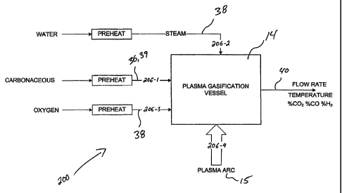
gasification reaction vessel 14, as well as means, as in 38 and/or 39, for
adding one or
more process additives, such as steam, oxidant, and/or carbon-rich material
additives
(the latter of which is optionally provided as a secondary feedstock 39), as
required
for maintaining the gasification processes at an optimal set point. The
gaseous
products exit the gasification reaction vessel 14 via one or more output gas
outlets, as
in 40.
In one embodiment, the application of plasma heat (e.g. via a plasma heat 15
source
such as a plasma torch and the like), in conjunction with the input of process
additives, such as steam and/or oxygen and/or carbon-rich material (e.g. as a
secondary feedstock 39, etc.), helps in controlling the gas composition. The
system
may also utilize plasma heat to provide the high temperature heat required to
gasify the feedstock and/or to melt the by-product ash and convert it to a
glass-like
product with commercial value.
Various embodiments of the present system 10 also provide means for managing
the
solid by-product of the gasification process. In particular, the invention
provides a
solid residue handling subsystem 16 for the conversion of the solid by-
products, or
residue, resulting from feedstock-to-energy conversion processes, into a
vitrified,
homogenous substance having low leachability. The solid by-products of the
gasification process may take the form of char, ash, slag, or some combination
thereof.
Illustratively the solid residue handling subsystem 16 comprises a solid
residue
conditioning chamber or region 42, a plasma heating means 44, a slag output
means
46, and a controlling means (which may be operatively linked to the overall
control
subsystem 200 of the system 10), whereby plasma heat is used to cause solids
to melt,
blend and chemically react forming a dense silicometallic vitreous material
that, when
poured out of the chamber or region 42, cools to a dense, non-leachable,
silicometallic
solid slag. In particular, the invention provides a solid residue conditioning
chamber
or region 42 in which the solid residue-to-slag conversion is optimized using
the
integrated control subsystem to control the plasma heat rate and solid residue
input
rate to promote full melting and homogenization.
12
CA 02610806 2007-12-03
WO 2006/128285
PCT/CA2006/000881
Various embodiments of the present system 10 also provide means for the
recovery of
heat from the hot product gas. This heat recovery subsystem 18 (exemplary
embodiments of which are schematically illustrated in Figures 21 to 25)
comprises
means to transfer the hot product gases to one or more gas-to-air heat
exchangers 48
whereby the hot product gas is used to heat air or other oxidant, such as
oxygen or
oxygen enriched air. The recovered heat, in the form of the heated air (or
other
oxidant), may then optionally be used to provide heat to the gasification
process
(Figures 23 and 24), thereby reducing the amount of heat which must be
provided by
the one or more plasma heat sources 15 to drive the gasification process. The
recovered heat may also be used in industrial heating applications.
Optionally, the heat recovery subsystem additionally comprise one or more heat
recovery steam generators (HRSG) 50 to generate steam which can, for example,
be
used as a process additive in the gasification reaction (Figures 23 and 25),
or to drive
a steam turbine, as in 52, to generate electricity.
Also, as seen in Figures 21 and 22, the heat recovery subsystem 18 may also
include
additional heat recovery subsystems operatively extracting heat from various
other
system components and processes, such as via a plasma heat source cooling
process
53, a slag cooling and handling process 55, GQCS cooling processes 61, and the
like.
The heat recovery system 18 may also comprise a feedback control system, which
may be operatively coupled to the system's overall control subsystem 200, to
optimize the energy transfer throughout the system 10 (e.g. see Figures 12 and
13).
Various embodiments of the present gasification system 10 also provide a gas
quality
conditioning suite (GQCS) 20, or other such gas quality conditioning means
(exemplary embodiments of which are illustrated in greater detail in Figures 3
and 5),
to convert the product of the gasification process to an output gas of
specified
characteristics. The product gas is directed to the GQCS 20, where it is
subjected to a
particular sequence of processing steps to produce the output gas having the
characteristics required for downstream applications. The GQCS 20 comprises
components that carry out processing steps that may include, for example,
removal of
particulate matter 54 (e.g., via a baghousc, cyclone (Figure 5) or the like),
acid gases
13
CA 02610806 2007-12-03
WO 2006/128285
PCT/CA2006/000881
(HC1, H2S) 56, and/or heavy metals 58 from the synthesis gas, or adjusting the
humidity and temperature of the gas as it passes through the system 10. The
presence
and sequence of processing steps is determined by the composition of the
synthesis
gas and the specified composition of output gas for downstream applications.
The gas
quality conditioning system 20 may also comprise an integrated control
subsystem,
which may be operatively linked to the overall integrated control subsystem
200 of
the system 10, to optimize the GQCS process (e.g. see Figures 12 and 13).
Various embodiments of the present gasification system 10 also provide a
means, as
in means 22, for regulating the product gas, for example, by homogenizing the
chemical composition of the product gas and adjusting other characteristics
such as
flow, pressure, and temperature of the product gas to meet downstream
requirements.
This product gas regulating subsystem 22 enables a continual and steady stream
of
gas of defined characteristics to be delivered to downstream applications,
such as a
gas turbine 24 or engine, a fuel cell application 26, and the like.
In particular, the product gas regulating subsystem 22 of the present
invention
provides a gas homogenization chamber 25 (Figure 3) or the like (compressor 21
of
Figures 3, gas storage device 23 of Figure 2, etc.) having dimensions that are
designed
to accommodate a gas residence time sufficient to attain a homogeneous gas of
a
consistent output composition. Other elements of the present product gas
regulation
system are designed to meet the gas performance requirements of the downstream
application. The gas regulating system 22 may also comprises an integrated
feedback
control system, which may be operatively linked to the overall integrated
control
subsystem 200 of the system 10, to optimize the energetics and output of this
process
(e.g., see Figures 12 and 13).
With reference now to Figures 4 to 9, the person of skill in the art will
understand that
the present system 10 and integrated control subsystem 200, in their various
embodiments, may be used in a number of energy generation and conversion
systems
having numerous independent and/or combined downstream applications. For
instance, in the exemplary embodiment of Figure 4, the system 10, an
Integrated
Gasification Combined Cycle (IGCC) system, may produce output energy (e.g.
electricity) by providing both a syngas for use in one or more gas turbines
24, and
14
CA 02610806 2007-12-03
WO 2006/128285
PCT/CA2006/000881
steam, generated by cooling both the syngas and exhaust gas associated with
the gas
turbine 24 via one or more HRSG(s) 50, for use in one or more steam turbines
52.
In the exemplary embodiment of Figure 5, the system 10 combines an Integrated
Gasification Combined Cycle (IGCC) system with a solid oxide fuel cell system
26S,
the latter of which using a hydrogen-rich byproduct of the syngas to produce
energy
(e.g. electricity).
In the exemplary embodiment of Figure 6, the system 10 combines an Integrated
Gasification Combined Cycle (IGCC) system with molten carbonate fuel cell
system
26M, the latter of which, as in Figure 5, using a hydrogen-rich byproduct of
the
syngas to produce energy (e.g. electricity).
In the exemplary embodiment of Figure 7, the system 10 combines a solid oxide
fuel
cell system 26S, as in Figure 5, with one or more steam turbines 52 activated
by steam
generated by one or more HRSGs 50 recuperating heat from the syngas and the
fuel
cell output(s).
In the exemplary embodiment of Figure 8, a water-gas shift reactor 59 is added
to the
embodiment of Figure 7 to provide the hydrogen-rich syngas used in the solid
oxide
fuel cell system 26S.
In the exemplary embodiment of Figure 9, the solid oxide fuel cell system 26S
of
Figure 8 is replaced by a molten carbonate fuel cell system 26M.
As will be apparent to the person of skill in the art, the above exemplary
embodiments
of system 10 are not meant to be limiting, as one of skill in the art will
understand that
other such system configurations and combinations can be provided without
departing
from the general scope and spirit of the present disclosure.
Integrated Control Subsystem
With reference to Figures 1 to 3 and 10 to 15, the present system includes an
integrated Control subsystem 200. The integrated control subsystem 200
comprises
CA 02610806 2007-12-03
WO 2006/128285
PCT/CA2006/000881
system monitoring means 202 for measuring one or more system parameters to
generate data, computing means 204 (schematically illustrated by the exemplary
logic
boxes 30, 32 and 34 in Figure 15) for collecting and analyzing the data
generated by
the system monitoring means 202, and output means to send appropriate signals
to
effect change in one or more system regulators 206 located throughout the
system
(i.e., regulators 206-1, 206-2, 206-3 and 206-4 of Figures 14 and 15). The
integrated
control subsystem 200 monitors the system parameters and sends signals to the
appropriate system regulators to make real time adjustments to various
operating
parameters and conditions as required in response to data obtained relating to
measured parameters within the system 10. In one embodiment, the integrated
control
subsystem 200 provides a feedback control system to manage the energetics of
the
conversion of a carbonaceous feedstock to energy and maintain a reaction set
point,
thereby allowing the gasification processes to be carried out under optimum
reaction
conditions to produce a gas having a specified composition.
The overall energetics of the conversion of feedstock to gas can be determined
and
achieved using the present gasification system. Some factors influencing the
determination of the net overall energetics are: the BTU value and composition
of the
feedstock, the specified composition of the product gas, the degree of
variation
allowed for the product gas, and the cost of the inputs versus the value of
the outputs.
Ongoing adjustments to the reactants (for example, power for the plasma heat
source(s) 15 and/or 44, process additives 38 and/or 39, such as oxygen, steam,
and/or
carbon-rich material, the latter of which is optionally provided as a
secondary
feedstock 39, can be executed in a manner whereby the net overall energetics
are
assessed and optimized according to design specifications.
The control subsystem 200 of the present invention, therefore, provides a
means for
controlling in real time all aspects of the processes to ensure that the
processes are
carried out in an efficient manner, while managing the energetics and
maintaining the
reaction set point within certain tolerances. The real time controller is
therefore
capable of simultaneously controlling all aspects of the process in an
integrated
manner.
16
CA 02610806 2007-12-03
WO 2006/128285
PCT/CA2006/000881
The composition and flow of product gas from the reaction vessel 14 is
controlled
within predefined tolerances by controlling the reaction environment. The
temperature
is controlled at atmospheric pressure to ensure that the feedstock that is
injected into
the reaction vessel 14 encounters as stable an environment as possible. The
control
subsystem 200 of this invention provides means to control the amounts of
feedstock,
steam, oxygen and carbon-rich material that are fed into the reaction vessel
14.
Operating parameters which may be adjusted to maintain the reaction set point
include feedstock feed rate, process additive feed rate, power to induction
blowers to
maintain a specified pressure, and power to and position of the plasma heat
sources
(i.e. 15, 44). These control aspects will be discussed further having regard
to each
parameter.
With reference to Figures 12 and 13, and as briefly discussed above, the
integrated
control subsystem 200 may be integrated throughout the system 10 to monitor,
via
monitoring means 202, various system parameters, and implement, via regulating
means 206, various modifications to these parameters to manage the energetics
and
maintain each aspect of the process within certain tolerances. These
parameters,
which will be discussed in greater detail below, may be derived from processes
associated with one or more of the plasma gasification vessel 14, the solid
residue
handling subsystem 16, the plasma heat source(s) 15 and slag processing heat
source(s) 44, the heat recovery subsystem 18 (e.g. gas-to-air heat exchanger
48 and/or
IIRSG 50) and process additive inputs 38 associated therewith, the primary
and/or
secondary feedstock inputs 36, 39 (e.g. carbon-rich additives), the GQCS 20,
the
homogenization chamber 25, and any other processing element or module of the
system 10.
Furthermore, having access to these parameters and access, via the various
local
and/or remote storage devices 214 of computing means 204, to a number of
predetermined and/or readjusted system parameters, system operating ranges,
system
monitoring and control software, operational data, and optionally plasma
gasification
process simulation data and/or system parameter optimization and modeling
means
216 (e.g. see Figure 28), the integrated control subsystem 200 may further
interact
with the system 10 in order to optimize systcm outputs.
17
CA 02610806 2007-12-03
WO 2006/128285
PCT/CA2006/000881
System monitoring means
With reference now to Figures 10 to 15, a number of operational parameters may
be
regularly or continuously monitored using the system monitoring means 202 of
the
control subsystem 200 to determine whether the system 10 is operating within
the
optimal set point. In one embodiment of the invention, means, as in means 202,
are
provided to monitor the parameters on a real time basis, thereby providing an
instantaneous indicator of whether the system 10 is operating within the
allowed/tolerated variability of the set point. The parameters which can be
monitored
include, but are not limited to, the chemical composition, flow rate and
temperature of
the product gas, the temperature at various points within the system 10, the
pressure
of the system, and various parameters relating to the plasma heat source(s)
15, 44
(i.e., power and/or position).
The parameters are monitored in real time and the resulting data are used to
determine
if, for example, more steam/oxygen (or other oxidants) must be injected into
the
system (e.g. via regulating means 206-2), if the feedstock input rate needs to
be
adjusted (e.g. via regulating means 206-1), or if the temperature or pressure
in any of
the components of the system requires adjustment.
System monitoring means may be located as required in any of the components of
the
GQCS 20, the heat recovery subsystem 18, the solid residue handling means 16,
and
the product gas handling subsystem 22, if such subsystems are present.
Composition of product gas
As discussed previously, if the product gas is intended for use in the
generation of
electricity, then it is desirable to obtain products which can be used as fuel
to power
energy generators. In this case, the optimal energetics are measured by the
efficiency
with which energy may be generated using the gases produced.
The main components of the output gas as it leaves the reaction vessel 14 are
carbon
monoxide, carbon dioxide, hydrogen, and steam, with lesser amounts of
nitrogen.
18
CA 02610806 2007-12-03
WO 2006/128285
PCT/CA2006/000881
Much smaller amounts of methane, acetylene and hydrogen sulfide may also be
present. The proportion of carbon monoxide or carbon dioxide in the output gas
depends on the amount of oxygen which is fed into the reaction vessel 14. For
example, carbon monoxide is produced when the flow of oxygen is controlled so
as to
preclude the stoichiometric conversion of carbon to carbon dioxide, and the
process is
so operated to produce mainly carbon monoxide.
The composition of the product synthesis gas may be optimized for a specific
application (e.g., gas turbines 24 and/or fuel cell application 26 for
electricity
generation) by adjusting the balance between, for example, applied plasma heat
15,
oxygen and/or steam and/or carbon-rich process additives 38 (or via a
secondary
feedstock 39). Since addition of oxidant and/or steam process additives during
the
gasification process affects the conversion chemistry, it is desirable to
provide means,
such as monitoring means 202, for monitoring the syngas composition. The above-
described inputs of the reactants are varied, e.g. via regulating means 206,
to maintain
the parameters of the synthesis gas within predetermined tolerances which are
defined
by the end use of the synthesis gas.
Monitoring of the product gas can be achieved using various monitoring means
202
such as a gas monitor and gas flow meter. The gas monitor may be used to
determine
the hydrogen, carbon monoxide and carbon dioxide content of the synthesis gas,
the
value of which is useable in various control steps, as illustratively depicted
by the
exemplary logic boxes 30 and 32 of Figure 15. Composition of the product gas
is
generally measured after the gas has been cooled and after it has undergone a
conditioning step to remove particulate matter.
The product gas can be sampled and analyzed using methods well known to the
skilled technician. One method that can be used to determine the chemical
composition of the product gas is through gas chromatography (GC) analysis.
Sample
points for these analyses can be located throughout the system. In one
embodiment,
the gas composition is measured using a Fourier Transform Infrared (FTIR)
Analyser,
which measures the infrared spectrum of the gas.
19
CA 02610806 2007-12-03
WO 2006/128285
PCT/CA2006/000881
In one embodiment, the parameters of the product gas, such as temperature,
flow rate
and composition, may be monitored via monitoring means 202 located at the
axial
outlet vent 40 of the reaction vessel 14. In another embodiment, sampling
ports may
also be installed at any location in the product gas handling system. As
discussed
previously, regulating means 206 are provided to vary the inputs of the
reactants to
maintain the parameters of the product gas within predetermined tolerances as
defined
by the end use of the product gas.
An aspect of this invention may consist in determining whether too much or too
little
oxygen is being added during the gasification process by determining the
composition
of the outlet stream and adjusting the process accordingly. In a preferred
embodiment,
an analyzer, sensor or other such monitoring means 202 in the carbon monoxide
stream detects the presence and concentration of carbon dioxide or other
suitable
reference oxygen rich material.
It will be apparent that other techniques may be used to determine whether
mostly
carbon monoxide is being produced. In one alternative, the ratio of carbon
dioxide to
carbon monoxide may be determined. In another alternative, a sensor may be
provided to determine the amount of oxygen and the amount of carbon downstream
of
the plasma generator, calculating the proportion of carbon monoxide and carbon
dioxide and then making process adjustments accordingly. In one embodiment,
the
values of CO and I12 are measured and compared to target values or ranges. In
another embodiment, the product gas heating value is measured and compared to
target values or ranges.
The person of skill in the art will understand that these and other such
product gas
composition measurements, which may be carried throughout a given embodiment
of
the system 10 via the above or other such monitoring means 202, may be used to
monitor and adjust, via regulating means 206, the ongoing process to maximize
process outputs and efficiencies, and should thus not be limited by the
examples listed
above and provided by the illustrative system and control subsystem
configurations
depicted in the appended Figures.
CA 02610806 2007-12-03
WO 2006/128285
PCT/CA2006/000881
Temperature at various locations in system
In one embodiment of the invention, there is provided means, as in monitoring
means
202, to monitor the temperature at sites located throughout the system 10,
wherein
such data are acquired on a continuous or intermittent basis. Monitoring means
202
for monitoring the temperature in the reaction vessel 14, for example, may be
located
on the outside wall of the reaction vessel 14, or insidc the refractory at the
top, middle
and bottom of the reaction vessel 14.
Monitoring means 202 for monitoring the temperature of the product gas may be
located at the product gas exit 40, as well as at various locations throughout
the
product gas conditioning system (e.g. within GQCS 20). A plurality of
thermocouples
can be used to monitor the temperature at critical points around the reaction
vessel 14.
If a system for recovering the sensible heat produced by the gasification
process is
employed (such as a heat exchanger or similar technology), as in 18, a
monitoring
means 202 for monitoring the temperature at points in the heat recovery system
(for
example, at coolant fluid inlets and outlets) may also be incorporated. In one
embodiment, a gas-to-air heat exchanger 48, a heat recovery steam generator
(HRSG)
50 or both are used to recover heat from the hot gases produced by the
gasification
process. In embodiments employing heat exchangers, the temperature
transmitters are
located to measure, for example, the temperatures of the product gas at the
heat
exchanger inlets and outlets. Temperature transmitters are also provided to
measure
the temperature of the coolant after heating in the heat exchanger.
These temperature measurements can be used to ensure that the temperature of
the
product gas as it enters a respective heat exchanger does not exceed the ideal
operating temperature of that device. For example, in one embodiment, if the
design
temperature for a gas-to-air heat exchanger 48 is 1050 C, a temperature
transmitter on
the inlet gas stream to the heat exchanger 48 can be used to control both
coolant air
flow rates through the system and plasma heat power in order to maintain the
optimum product gas temperature. In addition, measurement of the product gas
exit
temperature may be useful to ensure that the optimum amount of sensible heat
has
been recovered from the product gas at all heat recovery stages.
21
CA 02610806 2007-12-03
WO 2006/128285
PCT/CA2006/000881
A temperature transmitter installed on the air outlet stream to measure the
temperature
of the heated exchange-air ensures that the process is carried out under
conditions that
ensure the process air is heated to a temperature appropriate for use in the
gasification
process. In one embodiment, the coolant air outlet temperature is, for
example, about
625 C, therefore a temperature transmitter installed on the air outlet stream
will
provide data that is used to determine whether adjustments to one or both of
the air
flow rates through the system and torch power in the plasma gasification
vessel 14
(e.g. via regulating means 206-4 of Figures 14 and 15) should be made in order
to
maintain the optimum product gas input temperature, which in turn can be used
to
control the temperature of the coolant air.
According to one embodiment of the invention, the control strategy sets a
fixed set
point for the optimum coolant air output temperature, for example, about 600
C, as
well as a fixed value for the HRSG gas exit temperature, for example, about
235 C.
Therefore, according to this embodiment, when the product gas flow is reduced,
the
product gas temperature at the exit of the gas-to-air heat exchanger 48 gets
cooler,
resulting in decreased steam production because the HRSG gas exit temperature
is
also set to a fixed value.
The same concept applies when the airflow through the system is reduced.
According
to one embodiment of the present invention, the exit coolant air temperature
remains
fixed therefore the exit product gas temperature for the gas-to-air heat
exchanger 48 is
hotter, therefore producing more steam in the HRSG 50. However, when airflow
through the system is reduced, product gas flow will consequently also reduce,
so the
increased inlet temperature to the HRSG 50 will only be momentarily high. For
example, if airflow is reduced to 50%, the maximum inlet gas temperature that
the
MSG 50 would momentarily see is approximately 800 C, which is within the
temperature limits of the heat exchanger design.
In one embodiment of the invention, the monitoring means 202 for monitoring
the
temperature is provided by thermocouples installed at locations in the system
10 as
required. Such temperature measurements can then be used, as described above,
by
the integrated control subsystem 200, as illustratively depicted by the
exemplary logic
box 34 of Figure 15. The person skilled in the art will understand that other
types of
22
CA 02610806 2007-12-03
WO 2006/128285
PCT/CA2006/000881
temperature measurements carried throughout a given embodiment of the system
10,
via the above or other such monitoring means 202, may be used to monitor and
adjust,
via regulating means 206, the ongoing process to maximize process outputs and
efficiencies, and should thus not be limited by the examples listed above and
provided
by the illustrative system and control means configurations depicted in the
appended
Figures.
Pressure of system
In one embodiment of the invention, there is provided monitoring means 202 to
monitor the pressure within the reaction vessel 14, as well as throughout the
entire
system 10, wherein such data are acquired on a continuous or intermittent
basis. In a
further embodiment, these pressure monitoring means 202 comprises pressure
sensors
such as pressure transducers located, for example, on a vertical vessel wall.
Data
relating to the pressure of the system 10 is used by the control subsystem 200
to
determine, on a real time basis, whether adjustments to parameters such as
plasma
heat source power or the rate of addition of (e.g. via regulating means 206-1
and 206-
4 of Figures 14 and 15) feedstock or process additives are required.
Variability in the amount of feedstock being gasified may lead to rapid
gasification,
resulting in significant changes in the pressure within the reaction vessel
14. For
example, if an increased quantity of feedstock is introduced to the reaction
vessel 14,
it is likely that the pressure within the vessel 14 will increase sharply. It
would be
advantageous in such an instance to have monitoring means 202 to monitor the
pressure on a continuous basis, thereby providing the data required to make
adjustments in real time, via regulating means 206, to parameters (for
example, the
speed of the induction blower) to decrease the system pressure.
In a further embodiment, a continuous readout of differential pressures
throughout the
complete system 10 is provided, for example, via a number of pressure
monitoring
means 202. In this manner, the pressure drop across each individual component
can
be monitored to rapidly pinpoint developing problems during processing. The
person
of skill in the art will understand that the above and other such system
pressure
monitoring and control means can be used throughout the various embodiments of
23
CA 02610806 2007-12-03
WO 2006/128285
PCT/CA2006/000881
system 10 via the above or other such monitoring means 202, to monitor and
adjust,
via regulating means 206, the ongoing process to maximize process outputs and
efficiencies, and should thus not be limited by the examples listed above and
provided
by the illustrative system and control means configurations depicted in the
appended
Figures.
Rate of gas flow
In one embodiment of the invention, there is provided monitoring means 202 to
monitor the rate of product gas flow at sites located throughout the system
10,
wherein such data are acquired on a continuous or intermittent basis.
The rate of gas flow through the different components of the system will
affect the
residence time of the gas in a particular component. If the flow rate of the
gas
through the reforming region of the gasification reaction vessel 14 is too
fast, there
may not be enough time for the gaseous components to reach equilibrium,
resulting in
a non-optimum gasification process. The person of skill in the art will
understand that
these and other such gas flow monitoring and control means can be used
throughout
the various embodiments of system 10 via the above or other such monitoring
means
202, to monitor and adjust, via regulating means 206, the ongoing process to
maximize process outputs and efficiencies via an integrated control subsystem,
such
as the exemplary control subsystem 200 depicted in Figures 14 and 15.
Computing Means
The integrated control subsystem 200 comprises means for controlling the
reaction
conditions and to manage the chemistry and energetics of the conversion of the
carbonaceous feedstock to the output gas. In addition, the control subsystem
200 can
determine and maintain operating conditions to maintain ideal, optimal or not,
gasification reaction conditions. The determination of ideal operating
conditions
depends on the overall energetics of the process, including factors such as
the
composition of the carbonaceous feedstock and the specified composition of the
product gases The composition of the feedstock may be homogeneous or may
fluctuate to certain degrees. When the composition of the feedstock varies,
the certain
24
CA 02610806 2007-12-03
WO 2006/128285
PCT/CA2006/000881
system parameters may require continuous or regular adjustment, via regulating
means 206, to maintain the ideal operating conditions.
The integrated control subsystem 200 can comprise a number of elements, each
of
which can be designed to perform a dedicated task, for example, control of the
flow
rate of one of the additives, control of the position or power output of one
of the one
or more plasma heat sources (e.g. 15, 44) of the gasification system, or
control of the
withdrawal of by-product. The control subsystem 200 can further comprise a
processing system, as in processor(s) 208 of computing means 204. In one
embodiment, the processing system can comprise a number of sub-processing
systems.
In one embodiment, each sub-processing system can be configured to implement a
reaction model that can mimic at least one aspect of the plasma reforming
reactions.
Each reaction model has its own model input and model output parameters and
can be
used to calculate changes of the model output parameters as an effect of
changes to
the model input parameters. Each reaction model can be used to perform an
assessment to help predict changes to the operating conditions of the
gasification
system before affecting any of the control elements of the system. Note that
each
reaction model can only be used within a predetermined range of operating
conditions
where the simulated predictions sufficiently accurately mimic processes of the
(real)
plasma reforming system.
The processing system can further be configured with partial models or a full
model
of the reaction processes of the gasification system. Partial models, topped
by the full
model, can be of enormous complexity and can be used to predict changes to an
ever
increasing number of operating conditions or can be used to expand the range
of
operating conditions within which the model is sufficiently accurate or valid.
The
higher the level of abstraction and completeness of the description of the
reaction
processes, the more powerful the predictions of the processing system.
Increasing
complexity of the full model, however, can affect the utility of the model for
predicting certain effects on the operating conditions of the gasification
system. Their
usefulness may be limited to predicting effects over short time periods or
small
parameter changes.
CA 02610806 2007-12-03
WO 2006/128285
PCT/CA2006/000881
Figure 28 provides an exemplary embodiment of such a system model, which may
be
used in conjunction with the integrated control subsystem 200 to define
various
operational parameters, and predicted results based thereon, for use as
starting points
in implementing the various processes of system 10. In one embodiment, these
and
other such models are used occasionally or regularly to reevaluate and/or
update
various system operating ranges and/or parameters of the system 10 on an
ongoing
basis. In one embodiment, the NRC HYSYS simulation platform is used and can
consider as inputs, any combination of input chemical composition, thermo-
chemical
characteristics, moisture content, feed rate, process additve(s), etc. The
model may
also take provide various optional interactive process optimizations to
consider, for
example, site and coal type specifics, maximization of energy recovery,
minimization
of emissions, minimization of capital and costs, etc. Ultimately, based on the
selected
model options, the model may then provide, for example, various operational
characteristics, achievable throughputs, system design characteristics,
product gas
characteristics, emission levels, recoverable energy, recoverable byproducts
and
optimum low cost designs.
Each reaction model can be implemented exclusively in hardware or in any
combination of software and hardware. A reaction model, as illustrated in
Figure 28,
can be described using any combination of an algorithm, a formula or a set of
formulae which can be processed by the processing system. If the reaction
model is
exclusively implemented in hardware it can become an integral part of the
processing
system.
The processing system and any one of the sub-processing systems can comprise
exclusively hardware or any combination of hardware and software. Any of the
sub-
processing systems can comprise any combination of none or more proportional
(P),
integral (I) or differential (D) controllers, for example, a P-controller, an
I-controller,
a PI-controller, a PD controller, a PID controller etc. It will be apparent to
a person
skilled in the art that the ideal choice of combinations of P. I, and D
controllers
depends on the dynamics and delay time of the part of the reaction process of
the
gasification system and the range of operating conditions that the combination
is
intended to control, and the dynamics and delay time of the combination
controller.
26
CA 02610806 2007-12-03
WO 2006/128285
PCT/CA2006/000881
Important aspects in the design of the combination controller can be short
transient
periods and little oscillation during transient times when adjusting a
respective control
variable or control parameter from an initial to a specified value. It will be
apparent to
a person skilled in the art that these combinations can be implemented in an
analog
hardwired form which can continuously monitor, via monitoring means 202, the
value
of a control variable or control parameter and compare it with a specified
value to
influence a respective control element to make an adequate adjustment, via
regulating
means 204, to reduce the difference between the observed and the specified
value.
It will further be apparent to a person skilled in the art that the
combinations can be
implemented in a mixed digital hardware software environment. Relevant effects
of
the additionally discretionary sampling, data acquisition, and digital
processing are
well known to a person skilled in the art. P, I, D combination control can be
implemented in feed forward and feedback control schemes.
Corrective control
In corrective, or feedback, control the value of a control parameter or
control variable,
monitored via an appropriate monitoring means 202, is compared to a specified
value.
A control signal is determined based on the deviation between the two values
and
provided to a control element in order to reduce the deviation. For example,
when the
output gas exceeds a predetermined 1-12:CO ratio, a feedback control means, as
in
computing means 204, can determine an appropriate adjustment to one of the
input
variables, such as increasing the amount of additive oxygen to return the
H2:CO ratio
to the specified value. The delay time to affect a change to a control
parameter or
control variable via an appropriate regulating means 206 is sometime called
loop
time. The loop time, for example, to adjust the power of the plasma heat
source(s) 15,
44, the pressure in the system, the carbon-rich additive input rate, or the
oxygen or
steam flow rate, can amount to 30 to 60 seconds.
In one embodiment, the product gas composition is the specified value used for
comparison in the feedback control scheme described above, whereby fixed
values (or
ranges of values) of the amount of CO and H2 in the product gas are specified.
In
27
CA 02610806 2007-12-03
WO 2006/128285
PCT/CA2006/000881
another embodiment, the specified value is a fixed value (or range of values)
for the
product gas heating value.
Feedback control is required for all control variables and control parameters
which
require direct monitoring or where a model prediction is satisfactorily. There
are a
number of control variables and control parameters of the gasification system
10 that
lend themselves towards use in a feedback control scheme. Feedback schemes can
be
effectively implemented in aspects of the control subsystem 200 for those
control
variables or control parameters which can be directly sensed and controlled
and
whose control does not, for practical purposes, depend upon other control
variables or
control parameters.
Feed forward control
Feed forward control processes input parameters to influence, without
monitoring,
control variables and control parameters. The gasification system can use feed
forward control for a number of control parameter such as the amount of power
which
is supplied to one of the one or more plasma heat sources (15, 44). The power
output
of the arcs of the plasma heat sources (15, 44) can be controlled in a variety
of
different ways, for example, by pulse modulating the electrical current which
is
supplied to the torch to maintain the arc, varying the distance between the
electrodes,
limiting the torch current, or affecting the composition, orientation or
position of the
plasma.
The rate of supply of process additives that can be provided to the
gasification reactor
vessel 14 in a gaseous or liquid modification or in a pulverized form or which
can be
sprayed or otherwise injected via nozzles, for example can be controlled with
certain
control elements in a feed forward way. Effective control of an additive's
temperature
or pressure, however, may require monitoring and closed loop feed back
control.
Fuzzy logic control and other types of control
Fuzzy logic control as well as other types of control can equally be used in
feed
forward and feedback control schemes. These types of control can substantially
deviate from classical P, I, D combination control in the ways the plasma
reforming
reaction dynamics are modeled and simulated to predict how to change input
variables
28
CA 02610806 2007-12-03
WO 2006/128285
PCT/CA2006/000881
or input parameters to affect a specified outcome. Fuzzy logic control usually
only
requires a vague or empirical description of the reaction dynamics (in general
the
system dynamics) or the operating conditions of the system. Aspects and
implementation considerations of fuzzy logic and other types of control are
well
known to a person skilled in the art.
It will be understood that the foregoing embodiments of the invention are
exemplary
and can be varied in many ways. Such present or future variations are not to
be
regarded as a departure from the spirit and scope of the invention, and all
such
modifications as would be apparent to one skilled in the art are intended to
be
included within the scope of the following claims.
Gasification Reaction Vessels for Use with This System
With reference now to Figures 1 to 3, and to Figures 16 to 20, the present
carbonaceous feedstock gasification system 10 comprises a gasification reactor
vessel
14 having one or more processing zones and one or more plasma heat sources, as
in
15. The gasification reaction vessel 14 also comprises means, as in 36, for
inputting
the feedstock into the reaction vessel, as well as means, as in 38 and/or 39,
for adding
one or more process additives, such as steam and/or oxygen/oxidant additives,
and/or
carbon-rich additives (the latter of which is optionally provided as a
secondary
feedstock 39) as required for maintaining the gasification processes at an
optimal set
point.
The gasification reaction vessel 14 can have a wide range of length-to-
diameter ratios
and can be oriented either vertically or horizontally. The gasification
reaction vessel
will have one or more gas outlet means 40, as well as means for removing solid
residue (e.g., char, ash, slag or some combination thereof) 16, which is
generally an
outlet disposed somewhere along the bottom of the chamber (e.g. slag chamber
42) to
enable the residue to be removed using gravity flow. In one embodiment, the
gasification reaction vessel 14 will use physical transfer means to remove the
solid
residue from the bottom of the vessel. For example, a hot screw may be used to
convey the ash by-product into a slag processing chamber 42. Means for
processing
and handling slag will be discussed in more detail later. Note that the slag
may also be
29
CA 02610806 2007-12-03
WO 2006/128285
PCT/CA2006/000881
processed in the same chamber in which the gasification occurs (Figures 16 to
19), or
in a separate chamber, as in slag chamber 42 of Figure 20.
In one embodiment of the present invention, the one or more sources of plasma
heat
15 assist in the feedstock-to-gas conversion process. In one embodiment of the
present invention, the use of plasma heat sources 15, in conjunction with the
input of
steam and/or oxygen process additives 38, helps in controlling the gas
composition.
Plasma heat may also be used to ensure the complete conversion of the off
gases
produced by the gasification process into their constituent elements, allowing
reformation of these constituent elements into the product gas having a
specified
composition. The product gas may then exit the gasification reaction vessel 14
via
one or more output gas outlets 40.
The gasification of carbonaceous feedstocks (i.e., the complete conversion of
the
carbonaceous feedstocks to a syngas) takes place in the gasification reaction
vessel
14, and can proceed at high or low temperature, or at high or low pressure. A
number
of reactions take place in the process of converting carbonaceous feedstocks
to the
syngas product. As the carbonaceous feedstock is gasified in the reaction
vessel, the
physical, chemical, and thermal processes required for the gasification may
occur
sequentially or simultaneously, depending on the reactor design.
In the gasification reaction vessel 14, the carbonaceous feedstock is
subjected to
heating, whereby the feedstock is dried to remove any residual moisture. As
the
temperature of the dried feedstock increases, pyrolysis takes place. During
pyrolysis,
volatile components are volatilized and the feedstock is thermally decomposed
to
release tars, phenols, and light volatile hydrocarbon gases while the coal is
converted
to char. Char comprises the residual solids consisting of organic and
inorganic
materials.
The resulting char may be further heated to ensure complete conversion to its
gaseous
constituents, leaving an ash by-product that is later converted to slag. In
one
embodiment, the gasification of carbonaceous feedstocks takes place in the
presence
of a controlled amount of oxygen, to minimize the amount of combustion that
can
take place.
CA 02610806 2007-12-03
WO 2006/128285
PCT/CA2006/000881
The combined products of the drying, volatilization and char-to-ash conversion
steps
provide an intermediate offgas product. This intermediate offgas gas may be
subjected to further heating, typically by one or more plasma heat sources and
in the
presence of a controlled amount of steam, to complete the conversion of the
carbonaceous feedstocks to the syngas. This final step is also referred to as
a
reformation step.
The one or more plasma heat sources can be positioned to make all the
reactions
happen simultaneously, or can be positioned within the reaction vessel to make
them
happen sequentially. In either configuration, the temperature of the pyrolysis
process
is elevated due to inclusion of plasma heat sources in the reactor.
The gasification reaction is driven by heat, which can be fueled by adding
electricity
or fossil fuels (e.g., propane) to heat the reaction chamber or adding air as
a reactant
to drive the exothermic gasification reaction, which provides heat to the
reaction.
Some gasification processes also use indirect heating, avoiding combustion of
the
feed material in the gasification reactor and avoiding the dilution of the
product gas
with nitrogen and excess CO2.
The design of some gasification reaction vessels 14 is such that the process
for
converting the feedstock to a syngas may take place in a one-stage process,
i.e., where
the gasification and reformation steps both take place generally in a single
zone
within the system. In such a case, the product gas exiting the gasification
reaction
vessel 14 will be a syngas product.
In one embodiment of the invention, it is conceived that the one stage process
takes
place within a single chambered reaction vessel 14, where the gasification and
reformation steps both take place in the same chamber. For example, the
reaction
vessel embodiments depicted in Figures 16 to 19 could be interpreted to
encompass
single chamber, and optionally single zone (i.e., particularly the embodiments
of
Figures 16 and 18) reaction vessels wherein both the gasification and
reformation
processes occur within the main chamber of the vessel 14 and, in the case of a
single
zone vessel, in proximity of the one or more plasma heat sources 15.
31
CA 02610806 2007-12-03
WO 2006/128285
PCT/CA2006/000881
In one embodiment of the invention, the conversion process takes place in two
stages,
first a feedstock to offgas stage, followed by a offgas to syngas
(reformation) stage.
In such a two stage process, it is conceived that at least two different zones
(a first
zone for the gasification step and a second zone for the reformation step)
within a
single chambered reaction vessel are required.
The design of other gasification reaction vessels 14 is such that the
feedstock to
syngas conversion process takes place in more than one zone, i.e., wherein the
gasification and reformation steps are separated to some extent from each
other and
take place in different zones within the system. In these kinds of
gasification reaction
vessels, the process occurs either in more than one zone within one chamber
(e.g. the
embodiments of Figures 17 and 19 could be interpreted to represent multi-zone,
single-chamber vessels), in separate chambers (e.g. the embodiment of Figure
20) or
some combination thereof, wherein the zones are in fluid communication with
one
another. Note that the slag may also be processed in a same chamber (Figures
16 to
19), or in a separate chamber, as in slag chamber 42 of Figure 20.
In a multi-region gasification reaction vessel, a first, or primary, zone is
used to heat
the feedstock to dry the feedstock (if residual moisture is present), extract
the volatile
constituents of the feedstock, and optionally convert the resulting char to a
gaseous
product and ash, thereby producing an offgas product, while a second zone is
used to
apply plasma heat to assure the complete conversion of the offgas into the
syngas
product. Where two or more distinct zones are used for the gasification of the
feedstock and the conversion of offgas to syngas, the product gas exiting the
final
region of the gasification reaction vessel is a syngas.
The gasification reaction vessel 14 of the present invention optionally
comprises one
or more process additive input means 38, which are provided for the addition
of gases
such as oxygen, air, oxygen-enriched air, steam or other gas useful for the
gasification
process, into the gasification reaction vessel 14. The process additive input
means 38
may also provide means for the addition of a carbon-rich process additive into
the
gasification vessel, which may also be provided via a secondary feedstock
input
means 39 (Figures 16 to 20 define a mixed feedstock input means which
illustratively
32
CA 02610806 2007-12-03
WO 2006/128285
PCT/CA2006/000881
combines the primary feedstock input means 36 and optional secondary feedstock
input means 39). Thus, the process additive input means 38 can include air (or
oxygen) input ports and/or steam input ports and/or carbon-rich material input
ports,
the latter of which is optionally provided via a secondary (or mixed)
feedstock option
39. These ports are positioned within the reaction vessel for the optimal
distribution
of process additives throughout the vessel. The addition of process additives
will be
discussed in greater detail later.
in one embodiment, the carbon-rich additive/feedstock is added to the main or
primary feedstock such that a mixed feedstock enters the gasification vessel
14 via the
input means 36 (combined inputs 36 and 39). The person of skill in the art
will
understand that various input configurations may be considered to input a
primary
feedstock, an optional secondary feedstock (e.g., a carbon-rich additive) and
a mixed
feedstock (combined primary and secondary feedstocks/carbon-rich additive).
The carbon-rich additive (or secondary feedstock) may be any material that is
a
source of carbon that can be added to the feedstock undergoing gasification to
increase the amount of carbon available for the gasification process.
Supplementing
the feedstock being gasified with a carbon-rich material helps ensure the
formation of
a product gas having a specified composition. Examples of carbon-rich
additives that
can be used in accordance with the present invention may include, but are not
limited
to, tires, plastics, or high-grade coal.
In one embodiment, the heat required to drive the gasification of the
carbonaceous
feedstock is provided by heated air. In such an embodiment, the gasification
reaction
vessel 14 comprises one or more heated air input means for the introduction of
heated
air to the gasification region. The heated air input means include exchange
air inlets.
These inlets are positioned within the reaction vessel to distribute the
heated air
throughout the reaction vessel 14 to initiate and drive the conversion of the
feedstock
to a gaseous product.
With reference to the exemplary embodiment of Figure 25, the gasification
reaction
vessel 14 depicted therein comprises a horizontally oriented gasification
chamber
which is subdivided into three gasification zones (e.g. 14-1, 14-2, 14-3)
which provide
33
CA 02610806 2007-12-03
WO 2006/128285
PCT/CA2006/000881
for the optimization of the extraction of gaseous molecules from carbonaceous
feedstock by sequentially promoting, each in a respective zone, drying,
volatilization
and char-to-ash conversion (or carbon conversion). This is accomplished by
allowing
drying of the feedstock to occur at a certain temperature range in a first
zone 14-1
prior to moving the material to a second zone 14-2, where volatilization
occurs at
another temperature range, prior to moving the material to a third zone 14-3
where
char-to-ash conversions (or carbon conversion) occurs at another temperature
range.
The three zones are schematically represented if Figure 29, wherein exemplary
reaction ratios are illustrated as progressing from a first zone where the
drying process
is most prominent over the volatilization and carbon conversion processes; a
second
zone wherein the volatilization process takes over; and a third zone where the
material
is practically completely dry, and the carbon conversion process takes over.
The horizontal expansion of the gasification process allows for the
optimization of the
gasification process by regionally promoting one or more of the stages of the
gasification process in response to the characteristics of the feedstock
material at that
particular location in the reaction vessel 14 of Figure 20. It would be
apparent to a
worker skilled in the art that this reaction vessel 14 could therefore be
segregated into
two, three, four or more steps depending on the characteristics of the
feedstock used.
The discussion below describes segregating the reaction vessel into three
steps. The
exemplary embodiment provided by vessel 14 of Figure 20, however, is not
technically restricted to three steps.
In one embodiment, means are provided to move the material through the
gasification
reactor in order to facilitate specific stages of the gasification process
(drying,
volatilization, char-to-ash conversion). To enable control of the gasification
process,
means to control the material movement through the gasification reactor is
also
provided. This lateral movement of material through the reaction vessel can be
achieved via the use of one or more lateral transfer units. This is achieved
with the
lateral transfer means by varying the movement speed, the distance each
lateral
transfer means moves and the sequence in which the plurality of lateral
transfer means
are moved in relation to each other. The one or more lateral transfer means
can act in
coordinated manner or individual lateral transfer means can act independently.
In
34
CA 02610806 2007-12-03
WO 2006/128285
PCT/CA2006/000881
order to optimize control of the material flow rate and pile height the
individual lateral
transfer means can be moved individually, at varying speeds, at varying
movement
distances, at varying frequency of movement. The lateral transfer means must
be able
to effectively operate in the harsh conditions of the reaction vessel and in
particular
must be able to operate at high temperatures.
The feedstock is delivered into the first step 14-1. The normal temperature
range for
the first step (as measured at the bottom of the material pile) lies between
300 and
900 C. The major process here is that of drying with some volatilization and
some
carbon-to-ash conversion. These processes occur mainly between 25 and 400 C.
As
the amount of drying tapers off, the temperature rises and a lateral transfer
means
moves the material towards the second step 14-2 as dictated by the integrated
control
system 200, or a subsystem thereof.
In the second step 14-2, the material is treated by process additives and has
a bottom
temperature range between 400 and 950 C. The main process occurring here is
that of
volatilization with the remainder of the drying operation as well as a
substantial
amount of carbon conversion (char combustion). These processes occur mainly
between 400 and 700 C. As the amount of volatilization tapers off, the
temperature
rises and the lateral transfer means moves the material towards the third step
14-3.
The third step temperature range lies between 600 and 1000 C. The major
process in
the third step 14-3 is that of carbon conversion with the remainder of
volatilization.
By this time most of the moisture has been removed from the material, and the
normal
temperature range is between 600 and 1000 C. As the amount of char conversion
tapers off, the temperature increases and the lateral transfer means moves the
solid
residue (mostly ash) through an outlet in the chamber to the solid residue
handling
= system 16 for further processing.
The lateral transfer means comprise lateral transfer units, motor means and
actuators.
The individual lateral transfer units comprise a moving element and a guiding
element. In one embodiment, the moving element is a shelf or platform in which
material is predominantly moved through the gasification reactor by sitting on
top of
the shelf! platform. A fraction of material may also be pushed by the leading
edge of
CA 02610806 2007-12-03
WO 2006/128285
PCT/CA2006/000881
the movable shelf / platform. The guide element can include one or more guide
channels located in the side walls of the reaction vessel, guide tracks or
rails, a guide
tough or guide chains.
The guide engagement members can include one or more wheels or rollers sized
to
movably engage the guide clement. In one embodiment of the invention, the
guide
engagement member is a sliding member comprising a shoe adapted to slide along
the
length of the guide track. Optionally, the shoe further comprises at least one
replaceable wear pad.
Power to propel lateral transfer means is provided by a motor means including
a
motor and drive system. In one embodiment the motor means is an electric
variable
speed motor which drives a motor output shaft in the forward or reverse
directions.
Optionally, a slip clutch could be provided between the motor and the motor
output
shaft. The motor may further comprise a gearbox.
Movement of the lateral transfer means can be effected by a hydraulic system,
chain
and sprocket drive, or a rack and pinion drive. These methods of translating
the
motor rotary motion into linear motion have the advantage that they can be
applied in
a synchronized manner at each side of a unit to assist in keeping the unit
aligned and
thus minimizing the possibility of the mechanism jamming.
In one embodiment, the sidewalls of the chamber slope inwards towards the
bottom to
achieve a small enough width for good air penetration while still having the
required
volume of material. The slope angle is made steep enough to assure that the
material
will drop towards the bottom of the chamber during processing.
In one embodiment, the gasification chamber 14 is a horizontal vessel with its
cross-
section optionally including a semi-circular dome or arched roof and a tapered
lower
section.
With reference to Figures 30 to 32, the drying, volatilization and char-to-ash
conversion steps of the gasification process described above can also be
carried out in
a vertically oriented gasification reaction vessel 14 (as schematically
depicted in
36
CA 02610806 2007-12-03
WO 2006/128285
PCT/CA2006/000881
Figures 32A and 328). In such an embodiment, the gasification reaction vessel
14
comprises one or more gasification chambers, at least one of which is
vertically
oriented and comprises a controllable solids removal means, as in rotating
wheel 130,
allowing for the optimization of the extraction of gaseous molecules from
carbonaceous feedstock(s) (e.g. single chamber - Figure 30, multiple chamber -
Figure
31).
As shown generally in Figures 30 and 31, the vertically oriented gasification
vessel
14comprises a feedstock input 36, 39 proximal to the top of a gasification
chamber,
one or more air inlets 38 proximal to the bottom of the chamber, a gas outlet
40, a
solid residue outlet 16 and a controllable solids removal means 130 at the
base of the
chamber for conveying solid residue out of the chamber. The gasification
chamber is
typically heated by one or more heating means. Thus, the material in the
vertically
oriented gasification reaction vessel essentially passes through a series of
zones each
of which experiences a temperature range that promotes a certain stage of the
gasification process.
As the material in the chamber is moved vertically from the upper feedstock
input
area down towards the solid residue outlet end through the action of the
solids
removal means 130 it goes through different degrees of drying, volatization
and char-
to-ash conversion. This is accomplished by the formation of a countercurrent
between
controlled movement of the feedstock material down through the chamber and the
upward movement of the preheated air being fed into the chamber from the base.
As
such, the temperature will be lowest at the top of the vertically oriented
material,
which allows drying to occur to a significant degree prior to the material
moving
downwards to another zone where the temperature will be higher allowing for
volatilization. Finally the material will move downwards to another zone where
the
temperatures is high enough to allow a significant amount of char-to-ash
conversion
to occur. Once the char-to-ash conversion is essentially complete, the solids
are
removed from the gasification chamber by the solids removal means.
In one embodiment, the gasification reaction vessel comprises more than one
chamber. In another embodiment, each of the temperature zones is located in a
different chamber.
37
CA 02610806 2007-12-03
WO 2006/128285
PCT/CA2006/000881
In order to ensure that the design objectives are achieved, the solid residue
outlet is
small in terms of vertical dimension. The configuration in which the solids
exit the
chamber is dependent on the design and function of the subsequent chamber and
can
be readily determined by one skilled in the art.
The gasification chamber is a refractory lined chamber with an internal volume
sized
to accommodate the appropriate amount of material for the required solids
residence
time. In one embodiment of the present invention, the gasification chamber is
tubular
or circular. In another embodiment, a lower portion of the inner wall is
sloped
inwardly above the solid residue outlet. In a further embodiment, the height
of the
gasification chamber is between about 1 and 3 times its diameter. In another
embodiment, the height of the gasification chamber is between about 1 and 2
times its
diameter. In a further embodiment, the height of the gasification chamber is
about 1.5
times its diameter.
During processing, feedstock is introduced into the reaction vessel at one end
through
the feedstock input and moves from the feed end through the various zones in
the
gasification reaction vessel towards the solid residue output end. As the feed
material
progresses through the vessel it losses its mass and volume as its volatile
fraction is
volatilized to form off-gas and the resulting char is reacted to form
additional off-gas
and ash. In one embodiment, the ash is subsequently heated to form slag.
During
processing, air (oxygen) is introduced through one or more air inlets 38
located at the
sides of the reaction vessel 14 proximal to the base.
Means are provided to move the material through the gasification reactor in
order to
facilitate specific stages of the gasification process (drying,
volatilization, char-to-ash
conversion). To enable control of the gasification process, means to control
the
material movement through the gasification reactor is also provided. The rate
of
vertical movement of material through gasification reactor is regulated via
the use of a
controllable solids removal means (e.g. wheel 130).
38
CA 02610806 2007-12-03
WO 2006/128285
PCT/CA2006/000881
The solid residue removal means 130 can be one of a variety of devices known
in the
art. Examples include, but are not limited to, screws, pusher rams, horizontal
rotating
paddles, horizontal rotating arms, horizontal rotating wheels.
In one embodiment, the solids removal device is a rotating paddle with thin
spokes
which moves the solid residue out of the chamber. In another embodiment, the
solids
removal device is a set of screws that move the solid residue out of the
chamber. In
this case the bottom portion of the sides is made slanting so that the solid
residue may
be directed towards the screws. In yet another embodiment, the solids removal
device is a single thin ram which moves the solid residue out of the chamber.
In this
case the bottom portion of the side opposite to the ram is made slanting so
that the
solid residue may be directed towards the ram leaving space for the exit hole.
In yet another embodiment of the invention, the solids removal device
comprises a
moving element and a guiding element. Suitable moving elements include, but
are not
limited to, a shelf / platform, pusher ram, plow, screw element or a belt. The
guide
element can include one or more guide channels located in the bottom wall of
the
gasification chamber, guide tracks or rails, guide trough or guide chains. The
guide
engagement members can include one or more wheels or rollers sized to movably
engage the guide element. In one embodiment of the invention, the guide
engagement
member is a sliding member comprising a shoe adapted to slide along the length
of
the guide track. Optionally, the shoe further comprises at least one
replaceable wear
pad.
The gasification reaction vessel 14 can be based on one of a number of
standard
reactors known in the art. Examples of reaction vessels known in the art
include, but
are not limited to entrained flow reactor vessels, moving bed reactors,
fluidized bed
reactors, and rotary kiln reactors, each of which is adapted to accept the
feedstock(s)
in the form of solids, particulates, slurry, liquids, gases or any combination
thereof,
through a feedstock input means 36, 39. The feedstock(s) is introduced through
one or
more inlets, which are disposed to provide optimum exposure to heating for
complete
and efficient conversion of the feedstock(s) to the product gas.
39
CA 02610806 2007-12-03
WO 2006/128285
PCT/CA2006/000881
Also, in accordance with one embodiment of the present invention, the
gasification
reaction vessel wall is lined with refractory material. The refractory
material can be
one, or a combination of, conventional refractory materials known in the art
which are
suitable for use in a vessel fora high temperature (e.g., a temperature of
about 1100 C
to 1400 C) non-pressurized reaction. Examples of such refractory materials
include,
but are not limited to, high temperature fired ceramics (such as aluminum
oxide,
aluminum nitride, aluminum silicate, boron nitride, zirconium phosphate),
glass
ceramics, chromia refractories and high alumina refractories containing
alumina,
titania, and/or chromia.
As is understood by those of skill in the art, different regions of the
gasification
reaction vessel may be lined with different refractory materials, according to
temperature and corrosion requirements of a particular region. For example, if
slagging is present, it may be advantageous to use a non-wetting refractory
material.
With reference still to Figures 16 to 20, 29 to 31, the person of skill in the
art will
understand that by moving the one or more plasma heat source 15, by adding
other
plasma heat sources, other sources of heat, and the like, the illustrated
vessels 14 may
be operated as single or multiple zone reaction vessels 14 without departing
from the
general scope and spirit of the present disclosure. Furthermore, it will be
understood
that the present coal gasification system 10 with integrated control subsystem
200
may be implemented with any of the above or other such gasification vessel
configurations. In fact, by monitoring one or more direct or indirect process
parameter
relevant to the gasification and/or reformation processes implemented within a
given
type of reaction vessel, whether these processes take place in a single zone
or multiple
zones within a single or multiple chamber, the control means 200 of the
present
system 10 may be used, via monitoring means 202, to monitor and adjust the
ongoing
processes to maximize, via regulating means 206, process outputs and
efficiencies.
The person of skill in the art will further understand that, although the
above
description provides a number of exemplary reaction vessel types,
configurations, and
materials to be used therefor, other reaction vessel types, configurations
and/or
materials may be used without departing from the general scope and nature of
the
present disclosure.
CA 02610806 2007-12-03
WO 2006/128285
PCT/CA2006/000881
Plasma Heating Means
Referring now to Figures 1 to 3 and 16 to 20, 29 to 31 the system of the
present
invention employs one or more plasma heating means, as in 15, to ensure
complete
conversion of the offgas produced by the gasification process to a product gas
having
a specified composition. Plasma heating means 15 may also be optionally
provided to
heat the carbonaceous feedstock to drive the initial gasification process.
In one embodiment of the present invention, the one or more plasma heat
sources 15
will be positioned to optimize the offgas conversion to a specified product
gas. The
position of the one or more plasma heat sources is selected according to the
design of
the gasification system, for example, according to whether the system employs
a one
stage or two stage gasification process. For instance, in one embodiment that
employs a two stage gasification process, the plasma heat source may be
disposed in a
position relative to the offgas inlet, and pointed in the direction of the
offgas inlet. In
= another embodiment that employs a one stage gasification process, the one
or more
plasma heat sources 15 may extend towards the core of the gasification
reaction
vessel. In all cases, the position of the plasma heat sources is selected
according to
the requirements of the system, and for optimal conversion of the offgas to
the
specified product gas.
Where more than one plasma heat source is used, the position of the heat
sources is
also selected to ensure that there is no conflict between two or more heat
sources, for
example, that no heat source is subjected to direct heat from another or that
there is no
arcing from one plasma heat source to another.
In addition, the location of the one or more plasma heat sources is selected
to avoid
impacting the wall of the reaction vessel with the plasma plume, thereby
avoiding the
formation of "hot spots".
A variety of commercially available plasma heat sources which can develop
suitably
high temperatures for sustained periods at the point of application can be
utilized in
the system. In general, such plasma heat sources are available in sizes from
about 100
41
CA 02610806 2007-12-03
WO 2006/128285
PCT/CA2006/000881
kW to over 6 MW in output power. The plasma heat source, or torch, can employ
one,
or a combination, of suitable working gases. Examples of suitable working
gases
include, but are not limited to, air, argon, helium, neon, hydrogen, methane,
ammonia,
carbon monoxide, oxygen, nitrogen, and carbon dioxide. In one embodiment of
the
present invention, the plasma heating means is continuously operating so as to
produce a temperature in excess of about 900 to about 1100 C as required for
converting the offgas to the syngas product.
In this respect, a number of alternative plasma torch technologies are
suitable for use
in the present system. For example, it is understood that inductively coupled
plasma
torches (ICP) may be employed. It is also understood that transferred arc and
non-
transferred arc torches (both AC and DC), using appropriately selected
electrode
materials, may also be employed. For example, electrode materials may be
selected
from, but are not limited to, copper and its alloys, stainless steel and
tungsten.
Graphite torches may also be used. Selection of an appropriate plasma heating
means
is within the ordinary skills of a worker in the art.
In one embodiment, the plasma heat sources 15 are located adjacent to one or
more
air/oxygen and/or steam input ports 38 such that the air/oxygen and/or steam
additives
are injected into the path of the plasma discharge of the plasma heat source
15.
hi a further embodiment, the plasma heat sources 15 may be movable, fixed or
any
combination thereof.
The process of the present invention uses the controllability of plasma heat
to drive
the conversion process and ensure that the gas flow and gas composition from
the
converter remain within predefined tight tolerances. Control of the plasma
heat also
assists in the efficient production of the product gases, irrespective of the
composition
of different carbonaceous feedstock sources or any natural variability in
sources of the
same type of feedstock.
In one embodiment, the control subsystem 200comprises regulating means 206 to
adjust the power of the plasma heat sources 15 to manage the net overall
energetics of
the reaction and maintain an optimal set point. In order to manage the
energetics of
42
CA 02610806 2007-12-03
WO 2006/128285
PCT/CA2006/000881
the reaction, the power to the plasma heat source 15 may be adjusted to
maintain a
constant gasification system temperature despite any fluctuations in the
composition
of the feedstock and corresponding rates of feed of steam, air/oxidant and
carbon-rich
process additives.
The control subsystem 200 controls the power rating of the plasma heat source
15
relative to the measured parameters such as the rate at which the carbonaceous
feedstock and process additives are introduced into the gasification reaction
vessel, as
well as the temperature of the system as determined by temperature sensors,
and other
such monitoring means 202, located at strategic locations throughout the
system 10.
The power rating of the plasma heat source 15 must be sufficient to
compensate, for
example, for loss of heat in the gasification reaction vessel 14 and to
process the
added feedstock efficiently.
For example, when the temperature of the reaction vessel 14 is too high, the
control
subsystem 200 may command a drop in the power rating of the plasma heat source
15
(e.g. via regulating means 206-4 of Figures 14 and 15); conversely, when the
temperature of the melt is too low, the control subsystem 200 may command an
increase in the power rating of the plasma heat source 15.
In one embodiment of the invention, the control subsystem 200 comprises
regulating
means 206 to control the position of the torch to ensure the maintenance of
the
optimal high temperature processing zone as well as to induce advantageous gas
flow
patterns around the entire reaction vessel 14.
One or more plasma heat sources, as in 44, are also optionally provided to
ensure
complete processing of the solid residue of the gasification process, as will
be
discussed later.
Feedstock input means
Still referring to Figures 1 to 3 and 16 to 20, 29 to 31, the invention
includes means,
as in input means 36, for introducing the carbonaceous feedstock to the
gasification
reaction vessel 14. The input means 36 are located to ensure that the
feedstock is
43
CA 02610806 2007-12-03
WO 2006/128285
PCT/CA2006/000881
deposited at an appropriate location in the reaction vessel 14 for optimum
exposure to
the gasifying heat source.
In one embodiment, the input means 36 is also provided with regulating means
206
for adjusting the feed rate to ensure that the feedstock is fed into the
reaction vessel 14
at an optimum rate for maintaining the gasification reaction at an optimum set
point.
In one embodiment, the control subsystem 200 comprises regulating means 206 to
adjust the rate of feedstock input to manage the net overall energetics of the
reaction.
For example, the rate of feedstock addition to the gasification reaction
vessel 14 can
be adjusted to facilitate the efficient conversion of the feedstock into the
product
gases. The rate of feedstock addition is selected to manage the overall
energetics of
the system according to the design specifications of the system 10, while
maintaining
the reaction set point within certain tolerances.
The selection of the input means 36 is made according to the requirements for
feed
dispersion, the operating pressure and the feedstock particle size. Input
means 36
may include, for example, a screw auger, a pneumatic transport system, a
plunger
system, a ram system, a rotary valve system, or a top gravity feed system.
In one embodiment, municipal waste can be used as a feedstock for the
gasification
process. Municipal waste may be provided in solid or liquid form. For the
gasification of solid wastes, the waste is introduced to the reaction vessel
14 through a
solid waste inlet feed port. The reaction vessel may also be designed to
optionally
include liquid waste feed inlet ports for the processing of liquid waste.
Feeding of the
waste into the reaction vessel 14 is commenced through the solid waste port
and/or
liquid waste ports (depending on the type of waste being processed).
A conditioning process for preparing the feedstock prior to introduction to
the
reaction vessel 14 may also be utilized. In one embodiment of the invention,
the
feedstock, depending on its nature and to increase efficiencies and achieve a
specified
product gas composition and energy outputs, can be pretreated, for example, to
reduce
its volume overall or increase its surface area to volume ratio by shredding,
44
CA 02610806 2007-12-03
WO 2006/128285
PCT/CA2006/000881
pulverizing, shearing, etc. In another embodiment, the feedstock may also
undergo a
pre-drying step to remove any residual moisture as required.
Process additive input means
Still referring to Figures 1 to 3 and 16 to 20,29 to 31 process additives may
optionally
be added to the reaction vessel 14 (e.g. via process additive ports, as in 38)
to
facilitate efficient conversion of the carbonaceous feedstock into product
gases. The
type and quantity of the process additives are very carefully selected to
optimize the
carbonaceous feedstock conversion while maintaining adherence to regulatory
authority emission limits and minimizing operating costs. Steam input ensures
sufficient free oxygen and hydrogen to maximize the conversion of decomposed
elements of the input waste into fuel gas and/or non-hazArdous compounds.
Air/oxidant input assists in processing chemistry balancing to maximize carbon
conversion to a fuel gas (minimize free carbon) and to maintain the optimum
processing temperatures while minimizing the relatively high cost plasma arc
input
heat. Carbon-rich additives (which may also be provided via secondary
feed.stock
input means 39) may also be added to supplement the carbon content of the
feedstock
undergoing gasification. The quantity of each additive is established and very
rigidly
controlled as identified by the outputs for the waste being processed. The
amount of
oxidant injection is very carefully established to ensure a maximum trade-off
for
relatively high cost plasma arc input heat while ensuring the overall process
does not
approach any of the undesirable process characteristics associated with
combustion,
and while meeting and bettering the emission standards of the local area.
For those embodiments having the production of electrical energy as an
objective, it is
advantageous to produce gases having a high fuel value. The production of high
quality fuel gases can be achieved by controlling reaction conditions, for
example, by
controlling the amount of process additives that are added at various steps in
the
conversion process.
The gasification reaction vessel 14, therefore, can include a plurality of
process
additive input ports 38, which may be provided for the addition of gases such
as
oxygen, air, oxygen-enriched air, steam or other gas useful for the
gasification
CA 02610806 2007-12-03
WO 2006/128285
PCT/CA2006/000881
process. The process additive input means 38 can include air input ports and
steam
input ports. These ports are positioned within the reaction vessel 14 for the
optimal
distribution of process additives through the reaction vessel 14. The steam
input ports
can be strategically located to direct steam into the high temperature
processing zone
and into the product gas mass prior to its exit from the reaction vessel. The
air/oxidant input ports can be strategically located in and around the
reaction vessel to
ensure fill coverage of process additives into the processing zone.
The process additive input ports 38 may also include input ports for the
addition of
carbon-rich materials, which may also be added via secondary feedstock input
means
39. Feedstocks useful for the gasification process of the present invention
can
conceivably be any carbonaceous materials, and as such, may be inherently
highly
variable in their carbon content. In one embodiment of the invention, the
system
provides a means, as in 38 and/or 39, for the addition of a carbon-rich
feedstock to
supplement the carbon content of the feedstock undergoing gasification. The
provision of a feedstock having a high carbon content increases the carbon
balance in
the product gases.
In one embodiment, there is also provided means for adding a carbon-rich
material to
the gasification reaction vessel 14. The carbon-rich material may be added by
premixing with the feedstock before addition to the reaction vessel 14 (mixed
feedstock input), or it may be added through a dedicated carbon-rich additive
port, as
in 38 and/or 39.
In one embodiment, the control subsystem 200 comprises means to control the
addition of a carbon-rich feedstock to manage the net overall energetics of
the
reaction to maintain an optimal reaction set point within certain tolerances
(e.g. via
regulating means 206-1 of Figures 14 and 15).
In one embodiment, the control subsystem 200 comprises regulating means 206 to
adjust the reactants to manage the net overall energetics of the reaction. For
example,
process additives may be added to the reaction vessel 14 to facilitate the
efficient
conversion of the feedstock into product gases. The type and quantity of the
process
additives are very carefully selected to manage the overall energetics of the
system
46
CA 02610806 2007-12-03
WO 2006/128285
PCT/CA2006/000881
according to the design specifications of the system, while maintaining the
reaction
set point within certain tolerances. In another embodiment of the invention,
the
control subsystem 200 comprises regulating means 206 to control the addition
of
process additives to maintain an optimal reaction set point. In another
embodiment of
the control subsystem 200, regulating means 206 are provided to control the
addition
of two or more process additives to maintain the reaction set point. In yet
another
embodiment, regulating means 206 are provided to control the addition of three
or
more process additives to maintain the reaction set point.
In those embodiments comprising a one stage process, i.e., where the
gasification and
reformation steps both take place in a single chamber gasification reaction
vessel 14,
it is advantageous to strategically locate additive input ports, as in 38
and/or 39, in
and around the gasification reaction vessel 14 to ensure full coverage of
process
additives into the processing zone. In those embodiments wherein the process
takes
place in two stages, i.e., the gasification and reformation take place in
discrete regions
within the system, it may be advantageous to locate certain additive ports
(for
example, steam inputs) proximal to the region where reformation by the plasma
torch,
or other such plasma heat source 15, takes place.
In a further embodiment, the control subsystem 200 comprises regulating means
206
for adjusting the additive inputs based on data obtained from monitoring and
analyzing the composition of the product gas, via various monitoring means 202
and
computing means 204 whereby these data are used to estimate the composition of
the
feedstock. The product gas composition data may be obtained on a continuous
basis,
thereby allowing the adjustments to additive inputs such as air, steam and
carbon-rich
additives to be made on a real-time basis (e.g. via regulating means 206-1,
206-2 and
206-3 of Figures 14 and 15). The product gas composition data may also be
obtained
on a intermittent basis.
The control subsystem 200 of the present invention, therefore, includes a
means, as in
regulating means 206 for introducing the additives into the system when the
concentration of certain product gases is not at an optimal level, as
monitored by
various monitoring means 202, according to predetermined target levels. For
example, in the event that a gas sensor detects too much carbon dioxide, the
control
47
CA 02610806 2007-12-03
WO 2006/128285
PCT/CA2006/000881
subsystem 200 may reduce the delivery of oxidant into the converter to reduce
the
production of carbon dioxide (e.g. via regulating means 206-3 exemplified in
Figures
15 and 16).
In one embodiment of the invention, the process is adjusted to produce mostly
carbon
monoxide, rather than carbon dioxide. In order to expedite the production of
carbon
monoxide in such an embodiment, the system will include a sensor, analyzer or
other
such monitoring means 202 for determining the amount of oxygen in the gaseous
output stream. If the correct amount of oxygen from steam or air/oxidant
inputs is
used in the gasification process, the product gas will be mainly carbon
monoxide. If
there is too little oxygen, a considerable amount of elemental carbon or
carbon black
may form which will ultimately plug up equipment downstream from the reaction
vessel 14. If there is too much oxygen in the system, too much carbon dioxide
will be
produced which has essentially no value, which is undesirable if the objective
of the
process is to produce a fuel gas. In response to too much carbon dioxide in
the system,
any steam or air/oxidant being injected is reduced or eliminated by an
appropriate
signal from the control subsystem 200 (e.g. via regulating means 206-2 and/or
206-3).
The conversion of a carbonaceous feedstock into fuel gas within the
gasification
reaction vessel 14 is an endothermic reaction, i.e., energy needs to be
provided to the
reactants to enable them to reform into the specified fuel gas product. In one
embodiment of the invention, a proportion of the energy required for the
gasification
process is provided by the oxidation of a portion of the initial gaseous
products or
carbonaceous feedstock within the reaction vessel 14.
Introduction of an oxidant into the reaction vessel 14 creates partial
oxidation
conditions within the reaction vessel 14. In partial oxidation, the carbon in
the coal
reacts with a less than the stoichiometric amount of oxygen required to
achieve
complete oxidation. With the limited amount of oxygen available, solid carbon
is
therefore converted into carbon monoxide and small amounts of carbon dioxide,
thereby providing carbon in a gaseous form.
Such oxidation also liberates thermal energy, thereby reducing the amount of
energy
that needs to be introduced into the gasification reaction vessel by the
plasma heat. In
48
CA 02610806 2007-12-03
WO 2006/128285
PCT/CA2006/000881
turn, this increased thermal energy reduces the amount of electrical power
that is
consumed by the plasma heat source 15 to produce the specified reaction
conditions
within the reaction vessel 14. Thus, a greater proportion of the electricity
produced by
converting the fuel gas to electrical power in an electric power generating
device (e.g.
fuel cell application 26, gas turbine 24, etc.) can be provided to a user or
exported as
electrical power, because the plasma heat source requires less electricity
from such an
electric power generating device in a system which employs the addition of an
oxidant.
The use of oxidant inputs as a process additive therefore assists in
maximizing the
conversion of carbon to a fuel gas and to maintain the optimum processing
temperatures as required while minimizing the relatively high cost plasma arc
input
heat. The amount of oxidant injection is very carefully established to ensure
maximum removal of carbon in gaseous form (CO and CO2). Simultaneously,
because the gasification of carbon reactions (combination with oxygen) are
exothermic, substantial quantities of heat are produced. This minimizes the
need for
relatively high cost plasma arc input heat while ensuring the overall process
does not
approach any of the undesirable process characteristics associated with
combustion.
In one embodiment of the invention, the oxidant is air.
Although less fuel gas will be produced within the reaction vessel when
partial
oxidizing conditions exist (because some of the fuel gas or feedstock is
oxidized to
liberate thermal energy, and thus, less fuel gas is available to an electric
power
generating device), the reduction in electrical consumption by the plasma heat
source(s) 15, 44 offsets a possible loss in electrical energy production. In
one
embodiment of the invention, the control subsystem 200 comprises means to
adjust
the addition of process additives to maintain an optimal reaction set point
(e.g. via
regulating means 206-2 and/or 206-3).
In one embodiment of the invention, the oxidant additive is selected from air,
oxygen,
oxygen-enriched air, steam or carbon dioxide. In those embodiments using
carbon
dioxide as an oxidizing process additive, the carbon dioxide may be recovered
from
the product gases and recycled into the process additive stream.
49
CA 02610806 2007-12-03
WO 2006/128285
PCT/CA2006/000881
The selection of appropriate oxidizing additive is made according to the
economic
objectives of the conversion process. For example, if the economic objective
is the
generation of electricity, the oxidizing additive will be selected to provide
the optimal
output gas composition for a given energy generating technology. For those
systems
which employ a gas engine to generate energy from the product gases, a higher
proportion of nitrogen may be acceptable in the product gas composition. In
such
systems, air will be an acceptable oxidant additive. For those systems,
however,
which employ a gas turbine 24 to generate energy, the product gases must
undergo
compression before use. In such embodiments, a higher proportion of nitrogen
in the
product gases will lead to an increased energetic cost associated with
compressing the
product gas, a proportion of which does not contribute to the production of
energy.
Therefore, in certain embodiments, it is advantageous to use an oxidizer that
contains
a lower proportion of nitrogen, such as oxygen or oxygen-enriched air.
In those embodiments of the present invention which seek to maximize the
production
of electrical energy using the fuel gases produced by the gasification
process, it is
advantageous to minimize the oxidation of the fuel gas which takes place in
the
gasification reaction vessel 14. In order to offset any decrease in the
production of
fuel gas due to partial oxidation conditions, steam may also be used as the
oxidizing
additive. The use of steam input as a process additive ensures sufficient free
oxygen
and hydrogen to maximize the conversion of decomposed elements of the input
feedstock into fuel gas and/or non-hazardous compounds.
For those embodiments having the production of electrical energy as an
objective, it is
advantageous to produce gases having a high fuel value. The use of steam as a
process additive is known in the art. The gasification of carbonaceous
feedstocks in
the presence of steam produces a syngas composed predominantly of hydrogen and
carbon monoxide. Those of ordinary skill in the chemical arts will recognize
that the
relative proportions of hydrogen and carbon monoxide in the fuel gas product
can be
manipulated by introducing different amounts of process additives into the
converter.
Steam input ports can be strategically located to direct steam into the high
temperature processing zone and/or into the product gas mass prior to its exit
from the
reaction vessel 14.
CA 02610806 2007-12-03
WO 2006/128285
PCT/CA2006/000881
Solid Residue Handling Subsystem
Still referring to Figures 1 to 3 and 16 to 20, 29 to 31 the present
carbonaceous
feedstock gasification system 10 also provides means for managing the solid by-
product of the gasification process. In particular, the invention provides a
solid
residue handling subsystem 16 for the conversion of the solid by-products, or
residue,
resulting from feedstock-to-energy conversion processes, into a vitrified,
homogenous
substance having low leachability.
In particular, the invention provides a solid residue handling subsystem 16 in
which
the solid residue-to-slag conversion is optimized by controlling the plasma
heat rate
and solid residue input rate to promote full melting and homogenization. In
one
embodiment, the solid residue handling subsystem comprises a solid residue
conditioning chamber 42 (or slag chamber) having a solid residue inlet, a
plasma
heating means, a slag outlet, optionally one or more ports, and a downstream
cooling
means for cooling and solidifying the slag into its final form. The integrated
control
subsystem 200 of the present invention also comprises regulating means 206 to
regulate the efficient conversion of the solid residue into slag by providing
monitoring
means 202 to monitor temperature and pressure throughout the solid residue
handling
subsystem 16, as well as means to control such operational paramctcrs as the
power to
the plasma heat source 44 and solid residue input rate.
The solid residue handling subsystem 16 of the present invention is adaptable
to treat
a solid residue stream coming out of any process that converts the
carbonaceous
feedstock into different forms of energy. This solid residue is typically in a
granular
state and may come from one or more sources such as the gasification reaction
vessel
14 and optionally the gas quality conditioning subsystem 20. In all cases, the
solid
residue is heated to a temperature required to convert the solids into a
vitrified,
homogeneous substance that exhibits extremely low leachability when allowed to
cool
and solidify. _The solid residue handling subsystem therefore ensures that the
solid
residue is brought up to an adequate temperature to melt and homogenize the
solid
residue. The solid residue handling subsystem also promotes the capture of
polluting
51
CA 02610806 2007-12-03
WO 2006/128285
PCT/CA2006/000881
solids (i.e., heavy metals) in the slag, as well as the formation of a clean,
homogeneous (and potentially commercially valuable) slag product.
In order to ensure complete processing of the solid residue, the solid residue
handling
subsystem is designed to provide sufficient residence time in the slag chamber
42. In
one embodiment, the system provides a residence time of at least 10 minutes.
In
another embodiment, the solid residue handling subsystem provides a residence
time
of up to 1 hour. In yet another embodiment, the solid residue handling
subsystem
provides a residence time of up to 2 hours.
The solid residue, which may take the form of char, ash, slag, or some
combination
thereof, will be removed, continuously or intermittently, from one or more
upstream
processes through appropriately adapted outlets and conveyance means as would
be
known to the skilled worker, according to the requirements of the system and
the type
of by-product being removed. In one embodiment, the solid residue is pushed
into the
slag chamber 42 through a system of hoppers and conveying screws.
The solid residue may be added in a continuous manner, for example, by using a
rotating screw or auger mechanism. For example, in one embodiment, a screw
conveyor is employed to convey ash to a slag chamber 42.
Alternatively, the solid residue can be added in a discontinuous fashion. In
one
embodiment of the invention, the solid residue input means, attached to the
solid
residue conditioning chamber 42, may consist of a system of conveying rams. In
such
an embodiment, limit switches are employed to control the length of the ram
stroke so
that the amount of material fed into the vessel with each stroke can be
controlled.
The solid residue input means will further include a control means such that
the input
rate of the solid residue can be controlled to ensure optimal melting and
homogenization of the solid residue material.
In one embodiment, a plasma heat source 44, is employed to heat and melt the
ash
into slag. The molten slag, at a temperature of, for example, about 1300 C to
about
1700 C, may be periodically or continuously exhausted from the slag chamber 42
and
52
CA 02610806 2007-12-03
WO 2006/128285
PCT/CA2006/000881
is thereafter cooled to form a solid slag material. Such slag material may be
intended
for landfill disposal_ Alternatively, the molten slag can be poured into
containers to
form ingots, bricks tiles or similar construction material. The solid product
may
further be broken into aggregates for conventional uses.
The solid residue handling subsystem 16, therefore, includes a slag output
means
through which molten slag is exhausted from the slag chamber 42. The output
means
may comprise a slag exit port 46, which is typically located at or near the
bottom of
the chamber 42 to facilitate the natural flow of the molten slag pool out of
the
chamber. The rate at which the molten slag flows out of the slag chamber may
be
controlled in a variety of ways that would be apparent to a person skilled in
the art.
For example, in one embodiment, the temperature differential between the point
closest to the plasma heating means and the exit point may be adjusted to
control the
re-solidification time of the molten slag, e.g., through adjustments in the
volume of
solid residue material allowed to pool in the chamber.
The slag output means may further be adapted to minimize heating requirements
by
keeping the slag chamber 42 sealed. In one embodiment, the output means
comprises
a pour spout or S-trap.
As discussed previously, it may also be advantageous to aim the plume of one
or more
of the plasma heat sources 44 towards the slag pool at, or around, the slag
exit port 46
to maintain the temperature of the molten slag and ensure that the slag exit
port 46
remains open through the complete slag extraction period. This practice will
also aid
in maintaining the slag as homogeneous as possible to guard against the
possibility
that some incompletely-processed material may inadvertently make its way out
of the
solid residue handling subsystem 16 during slag extraction.
The molten slag can be extracted from the solid residue handling subsystem in
a
number of different ways as are understood by those of skill in the art. For
example,
the slag can be extracted by a batch pour at the end of a processing period,
or a
continuous pour throughout the full duration of processing. The slag from
either pour
method can be poured into a water bath, where the water acts as a seal between
the
53
=
CA 02610806 2007-12-03
WO 2006/128285
PCT/CA2006/000881
external environment and the gasification system. The slag can also be dropped
into
carts for removal, into a bed of silica sand or into moulds.
The walls of the slag chamber 42 are lined with a refractory material that can
be one,
or a combination of, conventional refractory materials known in the art which
are
suitable for usc in a chamber for extremely high temperature (e.g., a
temperature of
about 1300 C to 1800 C) non-pressurized reactions. Examples of such refractory
materials include, but are not limited to, chromia refractories and high
alumina
refractories containing alumina, titania, and/or chromia. Selection of an
appropriate
material for lining the slag chamber is made according to their chemical
composition,
as well as their ability to resist the corrosive nature of the slag, by virtue
of their
highly dense (low porosity) microstructures. Corrosion rates can be decreased
with
lower temperatures or reduced heavy metal contamination. It is advantageous to
select a non-wetting refractory material where slagging is present.
A solid residue handling subsystem is designed for highly efficient heat
transfer
between the plasma gases and the solid residue in melting and homogenizing the
solid
residue. Thus, factors such as efficient heat transfer, adequate heat
temperatures,
residence time, molten slag flow, input solid residue volume and composition,
etc. are
taken into account when designing the solid residue handling subsystem.
As discussed above, the physical design characteristics of the solid residue
handling
subsystem are determined by a number of factors. These factors include, for
example,
the composition and volume of the solid residue to be processed. The solid
residue
that enters the slag chamber may be collected from more than one source
simultaneously. Accordingly, the internal configuration and size of the solid
residue
handling subsystem are dictated by the operational characteristics of the
input solid
residue to be processed.
Another factor to consider in the design of the solid residue handling
subsystem is the
residence time required to ensure that the solid residue is brought up to an
adequate
temperature to melt and homogenize the solid residue.
54
CA 02610806 2007-12-03
WO 2006/128285
PCT/CA2006/000881
The type of plasma heating means used, as well as the position and
orientation, of the
plasma heating means is an additional factor to be considered in the design of
the
solid residue handling subsystem. The plasma heating means must meet the
required
temperature for heating the solid residue to required levels to melt and
homogenize
the solid residue while allowing the resulting molten solid residue to flow
out of the
chamber.
In one embodiment, the solid residue handling subsystem comprises a slag
chamber
that can be conveniently removed and replaced in order to minimize downtime
due to
damage and wear.
The control subsystem 200 of the present invention regulates the efficient
conversion
of solid residue into slag by providing monitoring means 202 to monitor the
temperature and optionally pressure at sites located throughout the solid
residue
handling subsystem 16, wherein such data are acquired on a continuous or
intermittent basis. Monitoring means 202 for monitoring the temperature in the
chamber, for example, may be located on the outside wall of the chamber, or
inside
the refractory at the top, middle and bottom of the chamber. The control
subsystem
200 of the present invention also provides regulating means 206 for
controlling
operational parameters such as the power to the plasma heat source 44 and
solid
residue input rate.
For example, when the temperature of the melt is too high, the control
subsystem 200
may command a drop in the power rating of the plasma heat source 44;
conversely,
when the temperature of the melt is too low, the control subsystem 200 may
command
an increase in the power rating of the plasma heat source 44.
In one embodiment, the solid residue handling subsystem 16 can also comprise a
means for recovering heat (e.g. plasma heat source cooling means 53 and slag
cooling
means 55 of Figures 21 and 22, which can reduce the amount of waste heat
generated.
Such heat recovery means can include, for example, heat exchangers. In such an
embodiment, the control system can additionally control the operating
conditions of
the heat exchanger. The heat exchanger can have, for example, a number of
CA 02610806 2007-12-03
WO 2006/128285
PCT/CA2006/000881
temperature sensors, flow control elements, and other such monitoring and
regulating
means 202, 206.
The slag chamber may also include one or more ports to accommodate additional
structural elements/instruments that may optionally be required. For example,
a
viewport that may include a plurality of closed circuit television ports to
maintain
operator full visibility of all aspects of processing, including monitoring of
the slag
exit port 46 for formation of blockages. In another embodiment, the slag
chamber
may include service ports to allow for entry into the chamber for
scrubbing/cleaning,
maintenance, and repair. Such ports are known in the art and can include
sealable
port holes of various sizes.
Heat Recovery Subsystem
Referring now to Figures 1 to 3 and 21 to 25 the present carbonaceous
feedstock
gasification system 10 also provides means, as in 18, for the recovery of heat
from the
hot product gas. The heat recovery subsystem 18 comprises one or more gas-to-
air
heat exchangers, as in 48, whereby the hot product gas is used to provide
heated
exchange-air. The recovered heat (in the form of the heated exchange-air) may
then
optionally be used to provide heat to the gasification process, as
specifically
illustrated in Figures 2.5 and 24, thereby reducing die amount or hear woicti
mUst be
provided by the one or more plasma heat sources 15 required to drive the
gasification
process. The recovered heat may also be used in industrial or residential
heating
applications.
In another embodiment, the gas-to-air heat exchanger 48 is employed to heat an
oxidant, such as oxygen or oxygen-enriched air, which may then optionally be
used to
provide heat to the gasification process.
Different classes of gas-to-air heat exchangers 48 may be used in the present
system,
including shell and tube heat exchangers, both of straight, single-pass design
and of
U-tube, multiple pass design, as well as plate-type heat exchangers. The
selection of
appropriate heat exchangers is within the knowledge of the skilled worker.
56
CA 02610806 2007-12-03
WO 2006/128285
PCT/CA2006/000881
Due to the significant difference in the ambient air input temperature and hot
syngas,
each tube in the gas-to-air heat exchanger 48 preferably has its individual
expansion
bellows to avoid tube rupture. Tube rupture presents a high hazard due to
problems
resulting from air entering gas mixture. Tube rupture may occur where a single
tube
becomes plugged and is therefore no longer expanding/contracting with the rest
of the
tube bundle.
In order to minimize the hazard potential from a tube leak, the system of the
present
invention further comprises one or more individual temperature transmitters
associated with the product gas outlet of the gas-to-air heat exchanger 48.
These
temperature transmitters are positioned to detect a temperature rise resulting
from
combustion in the event of having exchange-air leak into the syngas conduit.
Detection of such a temperature rise will result in the automatic shut down of
the
induction air blowers which move the coolant air through the heat recovery
system.
The gas-to-air heat exchanger 48 is designed to have product gas flow in the
tubes
rather than on the shell side. In one embodiment, the product gas flows
vertically in a
"once through" design, which minimizes areas where build up or erosion from
particulate matter could occur. In one embodiment, the process air flows
counter-
currently on the shell side of the gas-to-air heat exchanger 48.
Optionally, the heat recovery subsystem additionally comprises one or more
heat
recovery steam generators 50 to generate steam, which can be used as a process
additive in the gasification reaction, as specifically illustrated in Figures
23 and 25 to
drive a steam turbine 52, or to drive rotating process equipment, such as
induction
blowers. Heat from the product gas is used to heat water to generate steam
using a
heat exchanging means 50, such as a heat recovery steam generator HRSG
(Figures 1,
2, 22), a waste heat boiler (Figure 23), and the like. In one embodiment, the
steam
produced using heat from the product gas is superheated steam.
With specific reference to Figures 23 to 25, the relationship between a gas-to-
air heat
exchanger, as in 48, and a heat recovery steam generator, as in 50, is
depicted in
accordance with one embodiment of the invention. The exchange-steam can also
be
used as a process steam additive during the gasification process to ensure
sufficient
57
CA 02610806 2007-12-03
WO 2006/128285
PCT/CA2006/000881
free oxygen and hydrogen to maximize the conversion of the feedstock into the
syngas product.
Steam that is not used within the conversion process or to drive rotating
process
equipment, may be used for other commercial purposes, such as the production
of
electricity through the use of steam turbines 52 or in local heating
applications or it
can be supplied to local industrial clients for their purposes, or it can be
used for
improving the extraction of oil from the tar sands.
In one embodiment, the heat recovery steam generator (or HRSG) 50 is located
downstream from the gas-to-air heat exchanger 48. In another embodiment, the
HRSG 50 employed in the present system is a shell and tube heat exchanger. The
HRSG 50 is designed such that the syngas flows vertically through the tubes
and
water is boiled on the shell side.
The gas-to-air heat exchanger 48 and the HRSG 50 are designed with the
understanding that some particulate matter will be present in the product gas.
The
particle size is typically between 0.5 to 350 micron. In one embodiment, the
product
gas velocities here are also maintained at a level high enough for self-
cleaning of the
tubes, while minimizing erosion.
If the temperature of the exiting product gas exceeds a predetermined limit,
this may
be an indication that the tubes are starting to plug, at which time the system
should be
shut down for maintenance. The heat exchangers are provided, as required, with
ports
for instrumentation, inspection and maintenance, as well as repair and/or
cleaning of
the conduits.
In one embodiment of the present invention, the system is run intermittently,
i.e.,
subject to numerous start-up and shut down cycles as required. Therefore, it
is
important that the equipment must be designed to withstand repeated thermal
expansion and contraction.
In order to maximize the amount of sensible heat which can be recovered from
the hot
product gases, as well as the heated exchange-air and steam produced by the
heat
58
CA 02610806 2007-12-03
WO 2006/128285
PCT/CA2006/000881
recovery system, the conduits between the components is optionally provided
with a
means for minimizing heat loss to the surrounding environment. Heat loss may
be
minimized, for example, through the use of an insulating barrier around the
conduits,
comprising insulating materials as are known in the art, or by designing the
plant to
minimize lengths of conduits.
With reference to Figures 1 and 26, in one embodiment of the present system
10, the
steam recuperated from the outputs of the various steam turbines 52 (e.g. a
steam
turbine operating from steam generated by an HRSG 50 used to cool the syngas
(line
86), a steam turbine operating from steam generated by an HRSG 50 used to cool
a
gas turbine/engine 24 and exhaust gas generated thereby (line 88), or any
combination
thereof), is cooled through an additional heat exchanger 90, which is fed by a
cooling
tower pump or the like. Upon exit from the exchanger 90, the cooled
steam/water is
pumped through a deaerator 92, fed by a soft water source with appropriate
chemicals, to remove air and excess oxygen therefrom, to then be processed
back to
the boiler feed water of the exhaust gas HRSG 50 (line 94), the syngas HRSG 50
(line
96), etc_
As presented above, the present gasification system 10 also comprises an
integrated
control subsystem 200 to optimize the transfer of energy throughout the
system,
thereby managing the energetics of the feedstock-to-energy conversion. The
energetics of the feedstock-to-energy conversion can be optimized using the
present
system, since the recycling of the recovered sensible heat back to the
gasification
process reduces the amount of energy inputs required from external sources for
the
steps of drying and volatilizing the feedstock. The recovered sensible heat
may also
serve to minimize the amount of plasma heat required to achieve a specified
quality of
syngas. Thus, the present invention allows for the efficient gasification of a
carbonaceous feedstock, wherein the gasification heat source is optionally
supplemented by air heated using sensible heat recovered from the product gas.
In order to optimize the efficiency of the present invention, the integrated
control
subsystem 200 also optionally provides a means for controlling the conditions
under
which the present process is carried out, as well as the operating conditions
of the
system according to the present invention. These control means, which may be
59
CA 02610806 2007-12-03
WO 2006/128285
PCT/CA2006/000881
incorporated into the overall integrated control subsystem 200, are provided
to
monitor one or more parameters, including, but not limited to, temperature and
gas
flow rates at specified locations throughout the system, and to adjust
operating
conditions accordingly, so as to maintain the system within defined
parameters.
Examples of operating conditions which may be adjusted by the control means,
via
regulating means 206, include one or more of the exchange-air flow rate, the
product
gas flow rate, the rate of feedstock input, the rate of input of process
additives such as
steam, and the power to the plasma heat sources 15, 44.
For example, temperature transmitters (and other such monitoring means 202)
may be
installed at specified locations throughout the system 10. The temperature
transmitters may be located to measure, for example, the temperatures of the
product
gas at the gas-to-air heat exchanger inlet and outlet, as well as the
temperatures of the
product gas at the HRSG inlet and outlet. Temperature transmitters may also be
provided to measure the temperature of the process air after heating in the
gas-to-air
heat exchanger 48, as well as to measure the temperature of the steam as it
exits the
HRSG 50.
These temperature measurements can be used to ensure that the temperature of
the
syngas as it enters a respective heat exchanger does not exceed the ideal
operating
temperature of that device. For example, if the design temperature for the gas-
to-air
heat exchanger 48 is 1050 C, a temperature transmitter on the inlet gas stream
to the
heat exchanger can be used to control both exchange-air flow rates through the
system
and plasma heat power in order to maintain the optimum syngas temperature. In
addition, measurement of the product gas exit temperature may be useful to
ensure
that the optimum amount of sensible heat has been recovered from the product
gas at
both heat recovery stages.
A temperature transmitter installed on the air outlet stream to measure the
temperature
of the heated exchange-air ensures that the process is carried out under
conditions that
ensure the process air is heated to a temperature appropriate for use in the
gasification
process. In one embodiment, the exchange-air outlet temperature is, for
example,
about 600 C, therefore a temperature transmitter installed on the air outlet
stream will
be used to control one or both of air flow rates through the system and plasma
heat
CA 02610806 2007-12-03
WO 2006/128285
PCT/CA2006/000881
source power in the plasma reforming chamber in order to maintain the optimum
syngas input temperature, which in turn can be used to control the temperature
of the
heated exchange-air.
According to one embodiment of the invention, the control strategy sets a
fixed set
point for the optimum heated exchange-air output temperature, for example,
about
600 C, as well as a fixed value for the HRSG gas exit temperature, for
example, about
235 C. Therefore, according to this embodiment, when the syngas flow is
reduced, the
exit gas temperature of the gas-to-air heat exchanger 48 gets cooler,
resulting in
decreased steam production because the HRSG gas exit temperature is also set
to a
fixed value.
The same concept applies when the airflow through the system is reduced.
According
to one embodiment of the present invention, the exit exchange-air temperature
remains fixed therefore the exit product gas temperature for the gas-to-air
heat
exchanger 48 is hotter, therefore producing more steam in the HRSG. However,
when airflow through the system is reduced, product gas flow will consequently
also
reduce, so the increased inlet temperature to the HRSG 50 will only be
momentarily
high. For example, if airflow is reduced to 50%, the maximum inlet gas
temperature
that the HRSG 50 would momentarily see is approximately 800 C, which is within
the
temperature limits of the heat exchanger design.
In addition, regulating means 206 for controlling an automatic valve for
venting
process air to the atmosphere are also optionally provided and incorporated
into the
overall system control means 200, if more air than required for the
gasification
process is preheated. For example, in some instances it is necessary to heat
more gas
than required for the process due to equipment considerations (e.g. when
starting a
shutdown procedure). In such instances, the excess exchange-air can be vented
as
required.
The system may further comprise means for monitoring one or more of syngas
composition, feedstock input rate, and process additive input rate (see
Figures 12 to
15) in order to provide additional information as may be required to implement
corrective procedures to maintain optimum processing conditions. Various such
61
CA 02610806 2007-12-03
WO 2006/128285
PCT/CA2006/000881
monitoring means 202 are known in the art and can be employed in the system of
the
present invention.
With reference to Figures 21 and 22, the heat recovery subsystem 18 described
above
may also provide for the cooling of the product gas as required for subsequent
particulate filtering and gas conditioning steps, namely with regards to the
GQCS 20
(e.g. GQCS cooling means 61), as well as provide for the cooling of the plasma
heat
sources 15, 44 (e.g. source cooling means 53), slag handling and processing
means
(e.g. slag cooling means 55), etc.
Gas Quality Conditioning Subsystem
With reference now to Figures 3 and 27 the present carbonaceous feedstock
gasification system 10 also provides a gas quality conditioning subsystem
(GQCS) 20,
or other such gas conditioning means, to convert the product of the
gasification
process to an output gas of specified characteristics.
Passage of the product gas through the GQCS 20 will ensure that the product
gas is
free of chemical and particulate contaminants, and therefore can be used in an
energy
generating system or in the manufacture of chemicals. This conditioning step
can also
be required in those embodiments of the invention which do not have the
generation
of energy or the manufacture of chemicals as an objective. For example,
treatment of
the product gas with the gas quality conditioning subsystem 20 can ensure that
the
product gas can be released through an exhaust mechanism while maintaining
strict
adherence to local emission standards.
In one embodiment, the objective for the gasification system 10 of the present
invention is to produce a fuel gas with specific characteristics (i.e.,
composition,
calorific heating value, purity and pressure) suitable for feeding into a gas
turbine 24
for production of renewable electrical energy. Because the fuel is generated
by the
pyrolysis/gasification of the carbonaceous feedstock through the process
described
herein, there will exist certain amounts of waste impurities, particulates
and/or acid
gases which are not suitable to the normal and safe operation of the gas
turbines.
62
CA 02610806 2007-12-03
WO 2006/128285
PCT/CA2006/000881
The product gas is directed to the GQCS 20, where it is subjected to a
particular
sequence of processing steps to produce the output gas having the
characteristics
required for downstream applications. As briefly presented above, the GQCS 20
comprises components that carry out processing steps that may include, but are
not
limited to, removal of particulate matter 54, acid gases (HCl, H2S) 56, and/or
heavy
metals 58 from the synthesis gas, or adjusting the humidity and temperature of
the gas
as it passes through the system. The presence and sequence of processing steps
required is determined by the composition of the synthesis gas and the
specified
composition of output gas for downstream applications. As presented above, the
system 10 also comprises integrated control subsystem 200 to optimize the GQCS
process.
In one embodiment, under vacuum extraction conditions of the induction fan of
a
gasification system, the hot product gas is continuously withdrawn from the
gasification system through an exit gas outlet(s) 40 of the gasification
system. A gas
transfer means, such as a pipe or other conduit is used to transfer the gas
from the
gasification chamber 14 to the GQCS 20.
It is also contemplated that one or more GQCSs 20 may be used, such as a
primary
GQCS and a secondary GQCS. In this case, the secondary GQCS may be used to
process material such as particulate matter and heavy metals that are removed
from
the gas stream in the primary GQCS. The output gas from the GQCS 20 can be
stored
in a gas storage tank 23 (Figure 2), fed through further processing means such
as a
homogenization chamber 25 (Figure 3) or alternatively, fed directly to the
downstream application for which it was designed (i.e. Figure 1).
As discussed above, it is advantageous to provide means for cooling the hot
product
gas prior to such a conditioning step. This cooling step may be required to
prevent
damage to heat-sensitive components in the system. In one embodiment, cooling
step
is carried out by the heat recovery subsystem 18, whereby the heat recovered
from the
product gas may also be optionally recovered and recycled for use in the
gasification
process (see Figures 23 to 25.
63
CA 02610806 2007-12-03
WO 2006/128285
PCT/CA2006/000881
In another embodiment, the gas from the gasification system is first cooled
down by
direct water evaporation in an evaporator such as quencher (Figure 3). In yet
another
embodiment, evaporative cooling towers (dry quench ¨ Figure 3) may be used to
cool
the syngas that enters the GQCS 20 from the gasification system. The
evaporative
cooling tower is capable of cooling the temperature of the syngas from about
740 C to
about 150-200 C. This process may be achieved using adiabatic saturation,
which
involves direct injection of water into the gas stream in a controlled manner.
The
evaporating cooling process is a dry quench process, and can be monitored to
ensure
that the cooled gas is not wet, i.e., that the relative humidity of the cooled
gas is still
below 100% at the cooled temperature.
As mentioned above, the GQCS 20 may comprise means, as in 54, for removing
particulate matter from the optionally cooled gas, as well as gaseous
contaminants not
compatible with downstream uses of the product gas, such as combustion in gas
turbines 24 to produce electricity, or as a feedstock 28 (Figure 2) in further
chemical
production processes. A particulate removal system 54 is incorporated to
remove
particulates that may be entrained in the fuel gas exiting the converter.
Particulate
removal systems 54 are widely available, and may include, for example, high-
temperature (ceramic) filters, cyclone separators (Figure 6), a venturi
scrubber (Figure
6), an electrofilter, a candle filter, a crossflow filter, a granular filter,
a water scrubber,
or a fabric baghouse filter (Figure 3), and the like, which are well known to
practitioners of gas conditioning.
As is known in the art, particulates can be removed in a number of ways
depending on
particulate size. For example, coarse particles may be removed using a cyclone
separator or filter. Smaller or finer particles may be removed using Wet ESP
or
baghouse filters (Figure 3). In one embodiment, with as much as 10 g/Nm3
particulate loading it a physical barrier that will remove particulate matter
with 99.9%
efficiency may be required. Wet ESP is driven by an electrostatic field and
may not
be suitable for use with gas streams of high oxygen content without control
mechanisms to trip the current if the oxygen content reaches a particular
level.
64
CA 02610806 2007-12-03
WO 2006/128285
PCT/CA2006/000881
In one embodiment, a first particle removal means is used to remove coarse
particles,
and a second particle removal means is used to remove smaller or finer
particles. In
one embodiment, the first particle removal means is a cyclone filter which can
remove
particles larger than 5-10 micron in size. In another embodiment, the second
particle
removal means is a baghouse filter.
Alternative embodiments may change the order of the various gas clean-up steps
to
use more efficiently the characteristics of alternative gas cleaning devices.
However,
depending on the specific particulate removal system employed, it may be
desirable to
cool the fuel gas exiting the reaction vessel 14 before it enters the
particulate removal
system 54 as previously mentioned. The cooling of the fuel gas may be of
particular
importance if a bag type filter is used for particulate removal, because bag
type filters
are often cellulose or organic polymer-based, and cannot withstand extremely
high
temperatures.
The dust is then collected and may be sent back to the gasification reaction
vessel 14
so that no hazardous, solid wastes are produced or generated in the gas
conditioning
system 20. Alternatively, the particulate may be directed to the slag
reservoir (see
Figure 3) to vitrify the scrubber solids into a non-leachable slag. In some
cases,
depending upon plant considerations and local regulations, solids from the gas
clean-
up system may be sent off-site for safe disposal.
There may also be provided means, as in 58, for removing mercury or other
heavy
metals from the product gas. For example, dry injection systems utilize a
calculated
amount of activated carbon which is injected in the gas stream with enough
residence
time so that fine heavy metal particles and fumes can adsorb in the activated
carbon
surface. Heavy metals adsorbed on activated carbon can be captured in a
baghouse
filter. Alternatively, a wet ESP system may be used to capture the heavy
metals
adsorbed on activated carbon. In one embodiment of the invention, the heavy
metal
particles adsorbed on activated carbon are captured in a baghouse.
An acid scrubbing system is also an effective technique to capture heavy
metals. This
system requires the passage of the gas containing heavy metals to be passed
through a
packed column with low pH (normally 1-2) solution circulation. Heavy metals
and
CA 02610806 2007-12-03
WO 2006/128285
PCT/CA2006/000881
heavy metal compounds react with acid to form their stable compounds. With
this
technique the heavy metal concentration in the circulation solution will
increase and
thus treatment of the resulting waste water may be required. In one
embodiment, the
GQCS 20 comprises an acid scrubbing system to remove heavy metals.
In one embodiment, the mercury removal means are provided by an activated
carbon
mercury polisher (Figure 3). An activated carbon filter bed can be used as the
final
polishing device for heavy metal. The product gas is passed through activated
carbon
bed that will adsorb heavy metal (mainly mercury) from the gas stream.
Normally
activated carbon filters are used to achieve above 99.8 -99.9 % removal of
mercury
and used as a final polishing device with 7-8 inches of WC pressure drop.
An acid recovery subsystem 56 is coupled to the gas conditioning system 20, to
recover sulfur or sulfuric acid and hydrochloric acid (from chlorinated
hydrocarbons),
which may have a marketable value. The acid removal system 56 may include
scrubber systems (e.g. HCI scrubber 57 ¨ Figure 3), acid removal systems, and
other
conventional equipment related to sulfur and/or acid removal systems.
The product gas produced in the present gasification system will contain acid
gases
such as HC1 and H2S. The concentrations of these acid gases in the product gas
range
from about 0.05 to about 0.5% for HC1, and range from about 100 ppm to about
1000
ppm for H2S. In one embodiment, the expected concentration of HC1 is about
0.178
% and H2S is about 666 ppm (0.07%). The emission limit for HC1 is about 5 ppm
while for SO2 it is about 21 ppm.
Acid gas removal can be achieved by dry scrubbing or wet scrubbing. The main
components of dry scrubbing are a spray dry absorber and soda ash or lime
powder
injection before baghouse filtration. Normally with dry scrubbing it is
difficult to
achieve more than 99% acid removal efficiency.
If the amount of chlorine is of economically significant size, the chlorine
may be
reclaimed. If chlorine is present in a nuisance amount, it is removed in any
suitable
manner (e.g. water or wet scrubber, activated bauxite adsorption, etc.). The
gas may
be treated to remove components such as chlorine in a gas/liquid scrubber-
contactor
66
CA 02610806 2007-12-03
WO 2006/128285
PCT/CA2006/000881
(e.g. HCl scrubber 57). The greatest advantage of wet scrubbing is a large
contact area
for heat transfer and mass transfer with less pressure drop that will help sub
cooling of
the gas. Sodium hydroxide is the traditional alkaline solution used for wet
scrubbing.
In one embodiment, a packed column is used for scrubbing acid gas.
Sulfur compounds are among the first to recombine, either as elemental sulfur,
as
sulfur-oxygen compounds or sulfur-hydrogen compounds. In one embodiment where
the amount of sulfur compounds justifies the cost, the sulfur recovery
facility, as in
76, is positioned along the conduit at a location, adjacent the heat
exchangers, where a
temperature is reached where the sulfur compounds become stable. The type and
size
of the sulfur recovery facility 76 depends on the expected amount of sulfur in
the inlet
stream.
If the anticipated amount of sulfur is fairly low, an iron filing technique
may be used
to react sulfur with elemental iron to produce iron sulfide. This may be
accomplished
by circulating iron pellets between a compartment in the conduit and a
recovery
compartment.
For feedstocks that contain a high amount of sulfur, a second-stage liquid
washing
process is used to remove sulfur compounds from the gas. Sulfur may be
recovered by
any suitable technique, depending on the amount of sulfur anticipated in the
inlet
stream. Further downstream, an amine scrubber removes hydrogen sulfide and
carbon
dioxide from the gas stream leaving a stream mainly comprising hydrogen,
carbon
monoxide and an inert gas. Such amine scrubbers are known in the art and
generally
comprise an amine process wherein an aqueous solution of monoethanoloamine,
diethanoloamine, or methyldiethanoloamine is used to remove H2S from the
processed gas. Other methods for recovering sulfur may include, for example, a
Claus
plant, a Resox reduction process, a cold plasma hydrogen sulfide dissociation
process,
and the like.
In addition, suitable methods for the removal of sulfur include, for example,
wet
absorption with NaOH or triazine, dry adsorption with Sufatreat, biological
processes
such as Thiopaq, or selective oxidation, including liquid redox (Low CAT). In
one
embodiment, H2S is removed from the synthetic gas using Thiopaq (see Figure
3).
67
CA 02610806 2007-12-03
WO 2006/128285
PCT/CA2006/000881
Thiopaq is a two step process in which sour gas is scrubbed with a mild
alkaline
solution (at 8.5 to 9 pH) and the sulfur subsequently recovered (HS- is
oxidized to
elemental sulfur by a biological process). Other methods may include, but are
not
limited to, a moving bed zinc titama or ferrite adsorption process, oxidation
chemical
reaction processes (e.g. Stretford and SulFerox), and a selexol acid removal
process,
the later of which generally involving the use of a physical solvent (e.g.
polyethylene
glycol dimethyl ether) at high pressures (e.g. 300-1000 psig).
Furthermore, dioxins may be formed at a temperature of 250-350 C in the
presence of
carbon that will act as catalyst, although plasma gasification conditions are
known to
hinder their formation. For additional minimization of dioxin formation,
quenching
of synthesis gas is normally done in a quencher or spray dryer absorber to
ensure fast
quenching is done between the above temperature range. Activated carbon
injection in
the synthesis gas will absorb dioxin and furan on carbon surface, followed by
removal
in baghouse filters.
Demisters or reheaters could also be incorporated for moisture removal and/or
prevention of condensation. Heat exchangers can be included to reheat the fuel
gas to
the inlet temperature required by the downstream power generation equipment. A
compressor can also optionally be included to compress the fuel gas to the
inlet
pressures required by downstream power generation equipment.
In yet another embodiment, a humidity control means can be part of the GQCS
20.
The humidity control means functions to ensure that the humidity of the output
gas is
appropriate for the downstream application required. For example, a humidity
control
means may include a chiller to cool the gas stream and thus condense some
water out
of the gas stream. This water can be removed by a gas/liquid separator. In one
embodiment such treatment of the gas stream ensures that the gas stream
exiting from
the GQCS 20 has a humidity of about 80% at 26 C. The gas may then be stored,
for
instance in a gas storage device 23 (Figure 2).
68
CA 02610806 2007-12-03
WO 2006/128285
PCT/CA2006/000881
In another embodiment, the gas processing system can include means for the
recovery
of carbon dioxide and/or means for recovery of ammonia. Suitable means are
known
in the art
The product gas is also sampled for gas chromatography (GC) analyses to
determine
chemical composition. Sample points for these analyses are spread throughout
the
product gas handling/pollution abatement subsystem.
In one embodiment, the control subsystem 200 comprises means to adjust the
operating conditions in the conversion system, including the operating
conditions in
the GQCS 20, thereby managing the net overall energetics of the conversion
process,
and maintaining a set point for reaction conditions within a specified range
of
variability during the conversion of a carbonaceous feedstock to a product gas
having
a specified chemical and physical composition. This system can be automated
and
applied to a variety of gasification systems.
The control subsystem 200 may provide the following functions. In one
embodiment,
the control subsystem 200 may sense decrease in efficiency or alternate
functional
deficiency in a process of the GQCS 20 and divert the gas stream to a backup
process
or backup conditioning system. In another embodiment, the control subsystem
200
may provide a means for fine-tuning the steps of the GQCS 20 and providing
minimal
drift from optimal conditions.
The control subsystem 200 of this invention can include monitoring means 202
for
analyzing the chemical composition of the gas stream through the GQCS 20, the
gas
flow and thermal parameters of the process; and regulating means 206 to adjust
the
conditions within the GQCS 20 to optimize the efficiency of processing and the
composition of the output gas. Ongoing adjustments to the reactants (for
example,
activated carbon injection with sufficient residence time, pH control for the
HCI
scrubber) can be executed in a manner which enables this process to be
conducted
efficiently and optimized according to design specifications.
Subsystem for Regulating the Product Gas
69
CA 02610806 2007-12-03
WO 2006/128285
PCT/CA2006/000881
The present gasification system also optionally provides means for regulating
the
product gas, for example, by homogenizing the chemical composition of the
product
gas and adjusting other characteristics such as flow, pressure, and
temperature of the
product gas to meet downstream requirements. This product gas regulating
subsystem
22 enables a continual and steady stream of gas of defined characteristics to
be
delivered to downstream applications, such as a gas turbine 24 or engine.
As is understood by those skilled in the art, the gasification process may
produce
gases of fluctuating composition, temperature or flow rates. In order to
minimize the
fluctuations in the characteristics of the product gas, there is optionally
provided a gas
regulation subsystem 22 in the form of a capturing means useful for delivering
to
downstream equipment a product gas having consistent characteristics.
In one embodiment the present invention provides a gas regulation system 22
that
collects the gaseous products of the gasification process and attenuates
fluctuations in
the chemistry of the gas composition in a homogenization chamber 25, or the
like.
Other elements of the system optionally adjust characteristics of the gas such
as flow,
temperature and pressure to fall within ranges that are acceptable to the
downstream
applications. The system thereby regulates the characteristics of the product
gas to
produce a continual stream of gas with consistent characteristics for delivery
to a
downstream application, such as a gas engine or a gas turbine 24.
In particular, the product gas regulating subsystem 22 of the present
invention
provides a gas homogenization chamber 25 (Figure 3) or the like (e.g. the gas
compressor 21 of Figure 3, the gas storage device 23 of Figure 2, etc.) having
dimensions that are designed to accommodate a residence time sufficient to
attain a
homogeneous gas of a consistent output composition. Other elements of the
present
gas regulation system are designed to meet the gas performance requirements of
the
downstream application. The system also comprises a control subsystem 200 to
optimize the energetics and output of the process.
The composition of the product gas entering the regulation system of the
present
invention is determined in the gasification process. Adjustments made during
the
gasification process permit the product gas to be optimized for a specific
application
CA 02610806 2007-12-03
WO 2006/128285
PCT/CA2006/000881
(e.g., gas turbines 24 or fuel cell application 26 for electricity
generation).
Accordingly, the composition of the product gas can be tailored for particular
energy
generating technologies (for example, for specific gas engines or gas turbines
24) and,
for best overall conversion efficiency, according to the different types of
feedstocks
and process additives used, by adjusting the operational parameters of the
gasification
process.
The product gas leaving the gasification system may be within a defined range
of a
target composition, however, over time the product gas may fluctuate in its
characteristics due to variability in the gasification process such as
feedstock
composition and feed rate, as well as airflow and temperature fluctuations.
Similar to the control of the composition of the product gas, the flow rate
and
temperature of the product gas can be monitored, for example via monitoring
means
202, and controlled in the gasification system, for example via regulating
means 206,
in order to maintain the parameters of the gas within predetermined tolerances
defined
by the end use. Irrespective of these controls, fluctuations in flow rate and
temperature of the product gas, over time, will occur. In the case of flow
rate, these
fluctuations may occur on a second to second basis; and with temperature on a
per
minute basis. Typical variances in flow rate range from 7200 Nm3 to 9300 Nm3.
Conversion of product gas to a gas having a specified composition that meets
the
requirements of the particular application equipment, can be effected in the
regulation
system of the present invention. The regulation system comprises one or more
gas
homogenization chambers 25, or the like, having a product gas inlet means, a
regulated gas outlet means, and optionally an emergency exit port.
The product gas homogenization chamber 25 receives the product gas produced
from
a gasification system and encourages mixing of the product gas to attenuate
any
fluctuations in the chemical composition of the product gas in the
homogenization
chamber 25. Fluctuations in other gas characteristics, such as pressure,
temperature
and flow rate, will also be reduced during mixing of the product gas.
71
CA 02610806 2007-12-03
WO 2006/128285
PCT/CA2006/000881
The dimensions of the chamber are designed according to the performance
characteristics of the upstream gasification system and the requirements of
the
downstream machinery, with the objective of minimizing the size or the chamber
as
much as possible. The gas homogenization chamber 25 is designed to receive
product
gas from a gasification process and retain the gas for a certain residence
time to allow
for sufficient mixing of the gas in order to achieve a volume of gas with a
consistent
chemical composition.
The residence time is the amount of time that the product gas remains in the
homogenization chamber 25 before being directed to the downstream equipment.
The
residence time is proportional to the response time of the related
gasification system
to correct for variances in the fluctuations in the gasification reaction in
order to
achieve a gas composition that falls within accepted tolerance values. For
example,
the gas composition is retained in the homogenization chamber 25 long enough
to
determine whether it falls within the gas composition tolerance allowed for
the
particular downstream application as well as to make any adjustments to the
gasification process to correct for the deviance.
Additionally, residence time of the product gas in the homogenization chamber
25 is
determined by the amount of variance in the product gas characteristics. That
is, the
smaller the variance in product gas characteristics, the shorter the residence
time
required in the homogenization chamber 25 to correct for the variance.
For example, a gas engine may be selected for use with the present
gasification
system to generate electricity. The selected gas engine will have
The regulated gas exiting the regulation system of the present invention will
have
stabilized characteristics that meet the specifications of the downstream
application.
Typically, machine manufacturers will provide the requirements and tolerances
allowed by the specific machinery and would be known to the person skilled in
the
art.
Use of the Gasification System I The Process
72
CA 02610806 2007-12-03
WO 2006/128285
PCT/CA2006/000881
The system according to the present invention gasifies carbonaceous
feedstocks, using
a process for gasification of the feedstock which generally comprises the
steps of
passing the feedstock into a gasification reaction vessel 14 where it is
heated dried
and volatile components in the dried feedstock are volatilized. In one
embodiment of
the invention, heated air is used to further drive the complete conversion of
the
resulting char to its gaseous constituents, leaving an ash by-product The
combined
products of the drying, volatilization and combustion steps provide an offgas,
which is
further subjected to the heat from a plasma heat source 15 to convert the
offgas to a
hot gaseous product comprising carbon monoxide, carbon dioxide, hydrogen and
steam. Steam and/or air/oxidant process additives may be optionally added
(e.g. via
additive input means 38) at the gasification stage and/or the offgas
conversion stage.
In one embodiment of the invention, the process further comprises the step of
subjecting by-product ash to heating by means of a second plasma heat source
44 to
form a slag product.
The process of the present invention further comprises the steps of passing
the hot
product gas through a heat exchanging subsystem 18, transferring heat from the
hot
gas to a coolant. In one embodiment, the coolant is air.
The process of the present invention optionally comprises the steps of passing
the
cooled gas product into a second heat exchanger IS, transferring heat from the
cooled
gas to a coolant which is water to produce a further cooled gas product and
steam.
The process of the present invention maximizes net conversion efficiency by
offsetting the amount of electricity that has to be consumed to create the
heat which
drives the gasification process, to drive rotating machinery, and to power the
plasma
heat sources 15, 44. For applications having the objective of generating
electricity,
the efficiency is measured by comparing the energy consumed by the overall
gasification process with the amount of energy generated using the product gas
(for
example, to power gas turbines 24 or in fuel cell technologies 26), and
through the
recovery of sensible heat to generate steam to power steam turbines 52.
73
CA 02610806 2007-12-03
WO 2006/128285
PCT/CA2006/000881
The gasification process can further comprise a feedback control step of
adjusting one
or more of the feedstock input rate, the product gas flow rate, the
air/oxidant and/or
steam process additive input rate, the carbon-rich additive input rate and the
amount
of power supplied to the plasma heat sources based on changes in the flow
rate,
temperature and/or composition of the product gas. The feedback control step
thus
allows the flow rate, temperature and/or composition of the product gas to be
maintained within acceptable ranges.
In one embodiment of the present invention, the process further comprises the
step of
pre-heating the feedstock prior to adding to the gasification reaction vessel
14.
In one embodiment, the gasification process according to the present invention
employs the use of heated air from the gas-to-air heat exchanger 48 to heat
the
gasification reaction vessel to a temperature appropriate for gasifying a
carbonaceous
feedstock. In this embodiment, which is typically used at the start-up phase
of the
system 10, air is fed into the system, whereby it is heated by plasma heat to
provide a
hot start-up gas which then enters the gas-air heat exchanger 48 to generate
heated air.
The heated air is transferred to the heated air inlet means to heat up the
gasification
reaction vessel 14, such that the entire process can run without the use of
fossil fuels.
The invention will now be described with reference to a specific example. It
will be
understood that the following example is intended to describe an embodiment of
the
invention and is not intended to limit the invention in any way.
EXAMPLE
In general, the system of the present invention is used by feeding the
carbonaceous
feedstock along with the heat from a source such as a plasma heat source 15,
heated
air, or any other heat source as may be appropriate, into a gasification
reaction vessel
14 where the feedstock is subjected to sufficient heat to allow the
gasification reaction
to take place.
Heating of the feedstock results in removal of any residual moisture and
volatilization
of any volatile components, thereby providing a partially oxidized char
product.
74
CA 02610806 2007-12-03
WO 2006/128285
PCT/CA2006/000881
Further heating of the partially oxidized char product completely converts the
char to
its gaseous constituents, leaving an ash by-product, which can then be further
heated
and converted to slag.
Extra oxygen may be injected into the gasification reaction vessel to initiate
or to
increase the exothermic reactions that produce carbon monoxide, carbon dioxide
and
carbon particles. The exothermic reactions along with the heat optionally
provided by
the heated process air increase the processing temperature in the gasification
reaction
vessel 14.
In one embodiment, the processing temperature is between about 100 C to about
1000 C, although lower and higher temperatures are also contemplated. In one
embodiment of the present invention, the process employs an average
gasification
temperature within the reaction vessel is about 700 C +/- 100 C.
Reformation
The offgas which is formed in the gasification reaction vessel 14 is further
heated
with a plasma heat source 15 and optionally treated with steam. These
reactions are
mainly endothermic. In one embodiment of the present invention, the
temperature is
maintained in a range that is high enough to keep the reactions at an
appropriate level
to ensure complete conversion to the specified gas product, while minimizing
pollution production. In one embodiment, the temperature range is from about
900 C
to about 1300 C. Appropriate temperature ranges can readily be determined by
the
skilled worker.
The steam that is added in the reformation step acts to ensure formation of a
gas
product having a specified composition, while also reducing the exit
temperature of
the gas. In one embodiment, the exit temperature of the product gas is reduced
to
between about 900 C and about 1200 C. In another embodiment, the product gas
exit
temperature is reduced to an average temperature of about 1000 C +/- 100 C.
The product gas exits the plasma reforming zone at a temperature of about 800
C to
about 1100 C. The flow rate of the hot syngas is about 6000 Nm3/hr to about
9500
CA 02610806 2007-12-03
WO 2006/128285
PCT/CA2006/000881
Nm3/hr, preferably about 7950 Nm3/hr. The hot product gas then passes into a
gas-to-
air heat exchanger 48.
In one embodiment of the present invention where heat exchangers 18 are used
to
cool the hot product gas, air enters the gas-to-air heat exchanger 48 at
ambient
temperature, i.e., from about -30 to about 40 C. The air is circulated
through the
system using air blowers, entering the gas-to-air heat exchanger at a rate of
about
3000 Nm3/hr to 6000 Nm3/hr, preferably at a rate of about 4000 Nm3/hr to 4500
Nm3/hr, more preferably at a rate of 4350 Nm3/hr.
In one exemplary embodiment, the amount of carbonaceous feedstock, oxygen,
steam,
carbon-rich additive and power to the plasma heat sources 15 may be determined
on
the basis of monitoring the flow rate of the exit synthesis gas, the exit
temperature of
the exit synthesis gas and the composition of the exit gas.
With reference to Figures 14 and 15, the numerical value of the flow rate of
carbon
monoxide and carbon dioxide in the exit gases via lines 100 and 102 is
inputted into a
first processor (illustrated by logic box 30) along with the numerical value
of the feed
rate of coal in line 104 (e.g. obtained via regulating means 206-1). The first
processor
30 estimates the amount of carbon in the gasification reaction vessel 40 and
adjusts
the coal feed rate accordingly.
Output from first processor 30, and which provides a measure of the numerical
value
of the per cent carbon monoxide and the per cent carbon dioxide is inputted
via line
106 to a second processor 32 (illustrated by logic box 32) along with the
numerical
value of the per cent hydrogen via line 108, and the numerical values of steam
(e.g.
via regulating means 206-2) and oxygen (e.g. via regulating means 206-3) via
line
110. The second processor 32 estimates new oxygen and steam inputs to achieve
the
specified gas composition.
Output from the second processor 32 are inputted into a third processor 34 via
line
112 along with an input representative of the numerical value of the exit gas
temperature via line 114. The third processor 34 computes new plasma heat
source
76
CA 02610806 2007-12-03
WO 2006/128285
PCT/CA2006/000881
power (e.g. plasma torch power) which outputs as plasma heat source power
output
(e.g. sent to regulating means 206-4) via line 116.
Referring back to Figures 1 to 3, in one embodiment of the invention, the air
is heated
in the heat exchanger 48 to produce heated air having a temperature of about
500 C to
about 800 C, preferably to about 600 C. The hot product gas, in turn, is
cooled to a
temperature of about 500 C to about 800 C, preferably to about 730 C. The
heated air
is optionally used in the gasification reaction vessel 14 to gasify the
carbonaceous
feedstock, as discussed above.
Further sensible heat is recovered from the product gas after it exits from
the gas-to-
air heat exchanger 48 through the use of a heat recovery steam generator
(HRSG) 50.
The product gas enters the HRSG 50 at a temperature of about 500 C to about
800 C,
preferably at a temperature of about 73 0 C.
The FERSG 50 transfers heat from the hot product gas to a water input to
produce a
saturated steam having a temperature of about 180 C to about 250 C, preferably
about
235 C, at a pressure of about 250 psig to about 350 psig, preferably about 300
psig.
In one embodiment, the water input into the steam generator is available at
about 50 C
to 95 C, preferably at about 90 C.
In one embodiment, the cooled syngas is further passed through a gas
conditioning
stage (e.g. GQCS 20). Therefore, the product gas temperature at the HRSG exit
should preferably not exceed 235 C.
After the gas conditioning stage, the product gas is optionally stored in a
homogenization chamber 25 (Figure 3), or the like.
Melting of By-Product Ash
In one embodiment of the invention, the solid ash by-product of the char
combustion
step is further optionally processed by melting with a second plasma heat
source 44.
Enough time is allowed when the particles are entrained in the slag pool to
ensure that
all volatiles and carbon are completely removed. As would be appreciated by a
77
CA 02610806 2007-12-03
WO 2006/128285
PCT/CA2006/000881
worker skilled in the art, the residence time is a fiinction of the particle
size. The heat
produced by the second plasma heat source 44 homogenizes the slag and allows
it to
be extracted while hot. The plasma heat source 44 heats the slag to a
temperature
between about 1100 'V and about 1600 C. In one embodiment, to temperature is
between about 1400 C and about 1650 C. This manipulation of the temperature
profiles can help to avoid wasting heat and later water to quench the slag in
the
bottom of the gasification reaction vessel 14.
Although the invention has been described with reference to certain specific
embodiments, various modifications thereof will be apparent to those skilled
in the art
without departing from the spirit and scope of the invention as outlined in
the claims
appended hereto.
The disclosure of all patents, publications, including published patent
applications,
and database entries referenced in this specification are specifically
incorporated by
reference in their entirety to the same extent as if each such individual
patent,
publication, and database entry were specifically and individually indicated
to be
incorporated by reference.
,
78