Note: Descriptions are shown in the official language in which they were submitted.
CA 02610872 2007-12-05
WO 2007/022738 1 PCT/DE2006/001097
Condensation Method
The invention relates to a condensation method having the features as set out
in
the generic clause of patent claim 1.
The efficiency of a power station is a factor which, in particular when
planning
new power stations, has a decisive influence on the economic viability.
Numerous efforts have thus been made to optimise steam power processes in
thermal power stations. In this context, particular emphasis is also placed on
the
condensation system. Especially in the case where such air-cooled condensers
are employed as are frequently used at the location of a power station in the
event of water shortage, the potential with regard to the efficiency of a
power
station has not yet been optimally exploited. Air-cooled condensers suffer
from
the basic drawback that only the dry air temperature can be used. In addition,
when operated at particularly low waste steam pressures, excessive cooling of
the condensate is likewise greater than in the case of water-cooled surface
condensers.
Air-cooled condensers normally have two condensation stages. In a first
condensation stage about 80-90% of the waste steam of a turbine is condensed.
A 100% condensation in the first condensation stage is virtually impossible
due
to the process-related parameters, such as e.g. the fluctuating outside
temperatures, so that a second condensation stage is in any case required for
the condensation of residual steam. For this reason, air-cooled condensers
installed in condensation or dephlegmatisation mode are frequently combined,
mariua\trle\ CM Condensatiou Method GEA PCT 21 08 2007
CA 02610872 2007-12-05
trfe'"CM Cou<lensation mcthod amendcd shtets
-2-
For this reason, air-cooled condensers installed in condensation or
dephlegmatisation mode are frequently combined, the condensation with
dephlegmatisation being provided for residual steam condensation, i.e. forming
the second condensation stage.
Normally, the condensate obtained is fed directly to a condensate collection
tank.
The condensate is subsequently supplied to a degasifier, in which treated
additional water is admixed, serving to replace losses which have occurred as
a
result of leakage, in order to be then fed again to an evaporator connected
upstream of the turbine by means of a feed pump. Since the condensate in the
degasifier must again be brought to boiling temperature for degasification
purposes, it is a drawback for the energy balance if the condensate has
previously been supercooled too much, since ultimately an increased energy
supply must be realised by employing primary fuels. The aim is, therefore, to
keep the excessive cooling of the condensate as low as possible in order to
minimise the employment of primary fuels. The aim is at the same time to keep
the amount of energy to be employed for the condensation of the turbine waste
steam likewise at a minimum.
From WO 90/07633 A a condensation method is known, in which a small portion
of the turbine waste steam flow is introduced into a condensate collection
tank in
order to heat the condensate. The intention of doing so is to avoid excessive
cooling of the condensate. The order of magnitude of the turbine waste steam
fiow, which is to be used for heating the condensate, is at about 1% of the
amount of steam passed through the main waste steam duct.
DE 22 57 369 Al provides an injection condenser, instead of a dephlegmator, to
serve as the second stage of a condensation device. Condensate obtained from
the condensation process is atomised inside the injection condenser. In order
to
increase the efficiency of the injection condenser, the condensate is pumped
into
AMENDED SHEET
CA 02610872 2007-12-05
f'
trle\C41 Condensution tnethad emcndcd shcets
!'-?
-2a -
heat exchanger elements, in order to cool it down even further. In this
manner,
the circulation process loses a lot of energy, resulting in a negative effect
on the
power station efficiency.
It is the object of the invention to provide a condensation method, wherein
the
excessive cooling of the condensate may be minimised and the power station
efficiency is simultaneously further improved.
This object is attained by a condensation method having the features of patent
claim 1.
It is an essential feature of the method according to the invention that the
condensate flow obtained in the condenser, prior to its introduction into a
condensate collection tank, is heated in a condensate heating stage
specifically
provided for this purpose. Heating of the condensate flow is performed by the
turbine waste steam during the condensate heating stage. The partial flow of
steam emerging from the condenser is simultaneously fed to a degasifier, in
which the partial flow of the steam heats colder additional feed water and is
itself
fully condensed.
AMENDED SHEET
_____ ,
CA 02610872 2007-12-05
WO 2007/022738 3 PCT/DE2006/001097
which the partial flow of the steam heats colder additional feed water and is
itself
fully condensed.
In the installation mode according to the invention a condensate heating
stage,
provided in addition to a degasifier, allows to significantly minimise the
excessive
cooling of the condensate and, as a result, to reduce the use of primary
fuels.
Model calculations have confirmed that excessive cooling of the condensate
observable in air-cooled condensers of conventional construction, may be
reduced in a range of about 1 - 6 K to about 0,5 K, as compared with the
temperature in the saturation state behind the turbine. The power station
efficiency increases according to the reduction of excessive cooling. In a 600
MW
power station the thermal efficiency may be improved by up to about 0,25%,
which, in view of the dimensions of the power plant, must not be seen as a
negligible quantity.
In the method according to the invention, the thermal energy of the turbine
waste
steam flow is utilised substantially more effectively, because it is not
released
into the environment by the condensers, but to a large extent flows into the
condensate, i.e. is preserved to the largest possible extent in the thermal
circuit.
The reduced energy losses bring about the intended improvement of the power
station efficiency. By heating the supercooled condensate, a simultaneous
condensation of a portion of the turbine waste steam flow is attained so that
less
waste steam enters the condenser. As a result, the condensers may possibly be
designed in smaller dimensions.
Advantageous embodiments of the inventive concept form the subject of the
subsidiary claims.
In the method according to the invention it suffices if the first condensation
stage,
i.e. the air-cooled condenser, is installed exclusively in dephlegmatisation
mode,
since a degasifier, required in any case in steam power processes, may be used
marina\trle\ CM Condensation Metl od GEA PCT 21 08 2007
CA 02610872 2007-12-05
WO 2007/022738 4 PCT/DE2006/001097
as the second condensation stage for condensing the excess steam. The
construction of the air-cooled condenser is thus simplified. The method
according
to the invention is, of course, also applicable to condensers which include
heat
exchanger elements installed both in condensation as well as in
dephlegmatisation mode.
In condensers instalied entirely in dephlegmatisation mode, a great portion of
the
waste steam of the turbine is already condensed. Nevertheless, for
thermodynamic reasons the partial steam flow emerging from the condenser so
adjusts itself automatically that an adequate volume flow is available in the
degasifier. In the case of the installation of the condensers in
dephlegmatisation
mode, the turbine waste steam flow is passed, as it were, to the degasifier
via the
condenser, emerging as partial steam flow. If the partial steam flow emerging
from the condenser is, in certain circumstances, not sufficient to adequately
heat
the colder additional feed water, it is possible to feed a further partial
steam flow
of the turbine waste steam flow directly, i.e. without making use of the
condenser.
An increased heat demand within the degasifier exists in particular, if
relatively
large amounts of treated additional feed water are fed into the material
cycle.
Since the additional feed water regularly exhibits a distinctly lower
temperature
than the condensate, it has, in this case as well, an advantageous effect on
the
energy balance of a condensation power station, if the partial waste steam
flow
from the condenser is used to degasify the additional feed water or to at
least
thermally promote the degasification.
The degasification of the additional feed water is performed primarily,
preferably
exclusively, in the degasifier provided for this purpose. Due to the heating
of the
condensate flow in the condensate heating stage, gases, produced by the
process, may escape in this case as well; however, the heated condensate has a
very low inert gas content so that only low volumes of gas arise during the
condensate heating stage. The gases may be removed by suction, just like in
the
case of a dephlegmator and a degasifier.
niarina\trle\ CM Condensatioti Metliod GEA PCT 21 08 2007
CA 02610872 2007-12-05
WO 2007/022738 5 PCT/DE2006/001097
If it is observed that due to the suction of air from the degasifier excess
steam is
sucked off as well, it is possible, in an advantageous further development of
the
invention, to condense this excess steam likewise by additional water. This as
well causes the additional water to be heated.
The heated additional feed water from the degasifier is preferably also
supplied
to the condensate heating stage, so that the additional feed water is heated
in
two stages. Although the condensate flow from the condenser suffices to
condense a portion of the turbine waste steam flow, full condensation of the
partial steam flow emerging from the condenser is, however, not possible in
practice for reasons of the energy balance. A condensation of the partial
steam
flow can be ensured in any event by an adequate amount of colder additional
feed water.
In order to improve the thermal transition during the condensate heating
stage, it
is provided to bring the condensate into contact with the turbine waste steam
flow
in droplet form. This can be done in that the condensate is guided over shaped
bodies and brought into contact with the turbine waste steam flow by way of
the
counter-flow method. The shaped bodies may for this purpose be arranged in
cascade-like fashion. A cascade-like arrangement of steel sheets without using
shaped bodies is, in principle, likewise conceivable. The decisive factor is
the
optimisation of the thermal transition from the turbine waste steam flow to
the
supercooled condensate. In this context, it is considered to be particularly
advantageous to atomise the condensate in order to form drops. The condensate
can thus be fed to the condensate heating stage by means of nozzles. The drops
of the supercooled condensate form low-temperature condensation seeds during
the condensate heating stage, thereby accelerating the condensation of the
turbine waste steam flow, while simultaneously increasing the temperature of
the
condensate in an advantageous manner in terms of energy.
mariua\trle~ CM Condensation Metltod GEA PCT 21 08 2007
CA 02610872 2007-12-05
WO 2007/022738 6 PCT/DE2006/001097
The invention is elucidated in more detail in what follows by way of the
embodiments illustrated schematically in the figures.
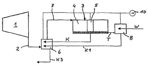
Figure 1 shows a very simplified steam power process of a thermal power
station,
wherein from a turbine 1 a turbine waste steam flow 2 is fed to a condenser 3
via
a duct. The condenser 3 is represented by an air-cooled condenser with heat
exchanger elements 4 installed in condensation mode as well as heat exchanger
elements 5 installed in dephlegmatisation mode. A large portion of the turbine
waste steam flow condenses inside the condenser 3.
Starting from the condenser 3, the condensate K obtained is fed to a
condensate
heating stage 6, during which the supercooled condensate K comes into contact
with the turbine waste steam flow 2. The condensate K is heated in such a
manner that a partial steam flow of the turbine waste steam flow 2 is already
condensed prior to the entry of the turbine waste steam flow K into the
condenser
3 via the duct 7 and is reintroduced directly to the material cycle as part of
the
condensate K3.
In addition, a degasifier 8 is provided, to which a partial steam flow T,
emerging
from the condenser 3, is fed. The partial steam flow T is condensed by
supplying
colder additional feed water W. In doing so, the additional feed water W is
heated and simultaneously degasified. The degasifier 8 serves, as it were, as
a
second condensation stage set up downstream. The condensate K1 from the
degasifier 8 is fed to the condensate heating stage 6, wherein the excessive
cooling of the condensates K, KI is utilised for the condensation of a portion
of
the turbine waste steam flow 2.
The embodiment according to Figure 2 differs primarily from that according to
Figure 1 in that the condenser 9 is installed exclusively in dephlegmatisation
mode. This can be seen from the entry of the steam in the lower edge region of
the condenser 9.
n arina'trle\ CM Condensation Metl od GEA PCT 21 08 2007
CA 02610872 2007-12-05
WO 2007/022738 7 PCT/DE2006/001097
A further difference resides in that, apart from the degasifier 8, there is
provided,
likewise as a second condensation stage, an excess steam condenser 11. The
excess steam condenser 11 serves to fully condense, i.e. by additional feed
water W, excess steam T2, which is already considerably enriched by inert
gases
from the condenser 9. This has the effect that the additional feed water W
heats
up and mixes with the condensate from the excess steam. The mixture is fed to
the condensate heating stage 6 as condensate flow K2.
In both embodiments an air-suction device 10 is provided in order to remove
gases from the material flow. The air-suction device 10 is connected both to
the
condenser 9 installed exclusively in dephlegmatisation mode or, respectively,
to
the heat exchanger elements 5 installed in dephlegmatisation mode, as well as
to
the condensate heating stage 6 as well as to the degasifier 8 or,
respectively, the
excess steam condenser 11. The entire condensate K3 is returned to a
condensate collection tank, not shown in more detail.
Figure 3 shows the calculated change in the thermal efficiency of the process
(in %), plotted against the condensate excessive cooling (in K). The basis for
the
values stated in this diagram is a calculation according to the formula
rith=P/(Qin+OQin), rith denoting the efficiency, P denoting the turbine
output, Qin
denoting the thermal feed and AQin denoting the additional heat for heating
the
condensate. The following values arise in a 600 MW power station:
Condensate tK C 38,50 38,00 37,00 36,00 35,00 34,00 33,00
temperature
Excessive AtK K 0,50 1,00 2,00 3,00 4,00 5,00 6,00
cooling
of condensate
Condensate hK kJ/kg 161,28 159,19 155,01 150,83 146,65 142,47 138,29
enthalpy
Waste heat Qab MW 800,26 801,03 802,57 804,11 805,66 807,20 808,74
Additional
heat for AQin MW 0,00 0,77 2,31 3,86 5,40 6,94 8,48
condensate
heating
Efficiency rith % 42,85 42,83 42,78 42,73 42,68 42,64 42,59
Change in Arith % 0,00 0,02 0,07 0,12 0,16 0,21 0,26
efficiency
marina\trle\ CM Condensation Metliod GEA PCT 21082007
CA 02610872 2007-12-05
WO 2007/022738 8 PCT/DE2006/001097
The following parameters are constant in this calculation: turbine output 600
MW,
waste steam mass flow 369 kg/s, waste steam enthalpy 2330 kJ/kg, waste steam
pressure 7 kPa, saturation steam temperature 39 C, heat supply 1400,26 MW.
The advantage of the method according to the invention resides in that the
excessive cooling of the condensate may be reduced considerably, resulting in
the improvement of the efficiency.
marina'trle\ CM Condensa[ion Method GEA PCT 21 08 2007
CA 02610872 2007-12-05
WO 2007/022738 9 PCT/DE2006/001097
Reference numerals:
1 - turbine
2 - turbine waste steam flow
3 - condenser
4 - heat exchanger element installed in condensation mode
- heat exchanger element installed in dephlegmatisation mode
6 - condensate heating stage
7 - duct
8 - degasifier
9 - condenser
- air-suction
11 - excess steam condenser
K - condensate
K1 - condensate
K2 - condensate
K3 - condensate
T - partial steam flow
T1 - partial steam flow
T2 - excess steam
W - additional feed water
marina\trlel CM Condensatioii Metliod GEA PCT 21 08 2007