Note: Descriptions are shown in the official language in which they were submitted.
CA 02611019 2014-02-04
WO 2006/1351195 PCT/US2006/023024
HYDROGEN GENERATING CARTRIDGES
BACKGROUND OF THE INVENTION
[0001] Fuel cells are devices that directly convert chemical energy of
reactants, Le., fuel and
oxidant, into direct current (DC) electricity. For an increasing number of
applications, fuel
cells are more efficient than conventional power generation, such as
combustion of fossil
fuel, as well as portable power storage, such as lithium-ion batteries.
[0002] In general, fuel cell technology includes a variety of different fuel
cells, such as alkali
fuel cells, polymer electrolyte fuel cells, phosphoric acid fuel cells, molten
carbonate fuel
cells, solid oxide fuel cells and enzyme fliel cells. Today's more important
fuel cells can be
divided into several general categories, namely (i) fuel cells utilizing
compressed hydrogen
(H2) as fuel; (ii) proton exchange membrane (PEM) fuel cells that use
alcohols, e.g.,
methanol (CI-130H), metal hydrides, e.g., sodium borohydride (NAIL),
hydrocarbons, or
other fuels reformed into hydrogen fuel; (iii) PEM fuel cells that can consume
non-hydrogen
fuel directly or direct oxidation fuel cells; and (iv) solid oxide fuel cells
(SOFC) that directly
convert hydrocarbon fuels to electricity at high temperature.
[0003] Compressed hydrogen is generally kept under high pressure and is
therefore difficult
to handle. Furthermore, large storage tanks are typically required and cannot
be made
sufficiently small for consumer electronic devices. Conventional reformat fuel
cells require
reformers and other vaporization and auxiliary systems to convert fuels to
hydrogen to react
with oxidant in the fuel cell. Recent advances make reformer or reformat fuel
cells promising
for consumer electronic devices. The most common direct oxidation fuel cells
are direct
methanol fuel cells or DMFC. Other direct oxidation fuel cells include direct
ethanol fuel
cells and direct tetramethyl orthocarbonate fuel cells. DMFC, where methanol
is reacted
directly with oxidant in the fuel cell, is the simplest and potentially
smallest fuel cell and also
has promising power application for consumer electronic devices. SOFC convert
hydrocarbon fuels, such as butane, at high heat to produce electricity. SOFC
requires
relatively high temperature in the range of 1000 C for the fuel cell reaction
to occur,
[0004] The chemical reactions that produce electricity are different for each
type of fuel cell.
For DMFC, the chemical-electrical reaction at each electrode and the overall
reaction for a
direct methanol fuel cell are described as follows:
[0005] Half-reaction at the anode:
- 1. -
CA 02611019 2014-02-04
WO 2006/135595
PCM7S2006/023024
CH3OH + H20 CO2 + 6H+ + 6c'
[0006] Half-reaction at the cathode:
1.502 + 6H' + 6e" 31.120
[0007) The overall fuel cell reaction:
C1-13011 + 1.502 CO2 + 21120
[0001i] Due to the migration of the hydrogen ions (1r) through the PEM from
the anode to
the cathode and due to the inability of the free electrons (e) to pass through
the PEM, the
electrons flow through an external circuit, thereby producing an electrical
current through the
external circuit. The external circuit may be used to power many useful
consumer electronic
devices, such as mobile or cell phones, calculators, personal digital
assistants, laptop
computers, and power tools, among others.
[0009] DMFC is discussed in U.S. Patent Nos. 5,992,008 and 5,945,231.
Generally, the
PEM is made from a polymer, such as Nafion6 available from DuPont, which is a
perfluorinated sulfonic acid polymer having a thickness in the range of about
0.05 mm to
about 0.50 mm, or other suitable membranes. The anode is typically made from a
Tetlonized
carbon paper support with a thin layer of catalyst, such as platinum-
ruthenium, deposited
thereon. The cathode is typically a gas diffusion electrode in which platinum
particles are
bonded to one side of the membrane.
[00010] Chemical metal hydride fuels are promising due to their relatively
higher
energy density, i.e., amount of hydrogen per mass or volume of fuel. In a
chemical metal
hydride fuel cell, sodium borohydride is reformed and reacts as follows:
Na8114 + 2H20 ¨4. (heat or catalyst) ¨4 4(H2) + (NaB02)
[00011] Half-reaction at the anode:
H2 --b= 2H+ + ze
[00012] Half-reaction at the cathode:
2(21-14 + 2e) + 02 ---)= 21120
-2-
CA 02611019 2014-02-04
WO 2006/135895 P(2T/US2006/023(024
=
[0OOD] Suitable catalysts for this reaction include platinum, ruthenium,
and other
metals. The hydrogen fuel produced from reforming sodium borohydride is
reacted in the
fuel cell with an oxidant, such as 02, to create electricity (or a flow of
electrons) and water
byproduct. Sodium borate (NaB02) byproduct is also produced by the reforming
process. A
sodium borohydride fuel cell is discussed in U.S. Patent No. 4,26:1,956.
[00014] Despite the potential benefits of higher energy density, chemical
metal hydride
fuels have not achieved the desired energy density for use with portable
electronic devices
including the amount of hydrogen that can be released from the fuel. Hence,
there remains a
need to reduce the energy density and maximize the release of hydrogen in
chemical metal
hydride fuels.
SUMMARY OF THE INVENTION
10015.1 The present. invention increases the amount of hydrogen produced or
released from
metal hydride fuels.
100161 The present invention also decreases the volume of a hydrogen
generating cartridge.
BRIEF .DESCRIPTION OF THE DRAWING
[0017] in the accompanying drawings, which forms a part of the specification,
and is to be
read in conjunction therewith and in which like reference numerals are used to
indicate like
parts:
[00181 Fig. l is a cross-sectional view of an apparatus usable with the
release of hydrogen
from metal hydride fuels;
100191 Fig. 2 is a cross-sectional view of another apparatus usable with the
present invention;
[0020j Fig. 3 is a cross-sectional view of the apparatus of Fig. 2 along line
3-3;
[0020.1] Fig. 4 shows the hydrogen pressure of a fixture over time in the
First Example;
[0020.2] Fig. 5 shows the mass of hydrogen generated in a fixture over time in
the First
Example;
[0020.31 Fig. 6 shows the rate of mass generation over time in the First
Example;
[0020.4] Fig. 7 shows the fuel cell run time and the instantaneous device run
in the First
Example;
[0020.5] Fig. 8 shows the hydrogen pressure over time in the Second Example;
[0020.6] Fig. 9 shows the hydrogen mass over time in the Second Example;
- 3 -
CA 02611019 2014-02-04
WO 2006/135895
PCIPUS2006/023024
[0020.7] Fig. 10 shows the mass generation rate over time in the Second
Example; and
[0020.8] Fig. 11 shows the fuel cell run time and the instantaneous device run
in the Second
Example.
DETAILED DESCRIPTION OF THE INVENTION
10021] As illustrated in the accompanying drawing and discussed in detail
below, the present
invention is directed to methods and compositions capable of maximizing the
release of
hydrogen from chemical hydride fuels, such as sodium borohydride (NaBH4), and
water. The
present invention is also directed to an apparatus that maximizes the release
of hydrogen fuels
from a reaction of chemical hydride fuels and water.
100221 Suitable known hydrogen generating apparatus using metal hydride fuels
are
disclosed in U.S. patent no. 7,674,540; U.S. patent no.7,529,470; U.S. patent
no. 7,481,858;
and U.S. patent no, 7,727,293.
[00231 Suitable chemical metal hydride fuels include, but are not limited to,
hydrides of
elements of Groups IA-IVA of the Periodic Table of Elements and mixtures
thereof, such as
alkaline or alkali metal hydrides, or mixtures thereof. Other compounds, such
as alkali
metal-aluminum hydridcs (alanates) and alkali metal borohydrides may also be
employed.
More specific examples of metal hydrides include, but are not limited to,
lithium hydride,
lithium aluminum hydride, lithium borohydride, sodium hydride, sodium
borohydride,
potassium hydride, potassium horohydride, magnesium hydride, calcium hydride,
and salts
and/or derivatives thereof. The preferred hydrides are sodium borohydride,
magnesium
borohydride, lithium borohydride, and potassium borohydride. Preferably, the
hydrogen-
bearing fuel comprises the solid form of NaBH4 or 114(3H4)2. In solid form,
Na8114 does not
hydrolyze in the absence of water and therefore improves shelf life of the
cartridge.
However, the aqueous form of hydrogen-bearing fuel, such as aqueous Nal3H4,
can also be
utilized in the present invention. When an aqueous form of NaBH4 is utilized,
the chamber
containing the aqueous Naffild also includes a stabilizer. Exemplary
stabilizers can include,
hut are not limited to, metals and metal hydroxides, such as alkali metal
hydroxides.
Examples of such stabilizers arc described in U.S. Patent No. 6,683,025.
Preferably, the
stabilizer is NaOH.
10024] The solid form of the hydrogen-bearing fuel is preferred over the
aqueous form. In
general, solid fuels are more advantageous than liquid fuels, because the
aqueous fuels
contain proportionally less energy than the solid fuels and the liquid fuels
are less stable than
- 4 -
CA 02611019 2014-02-04
WO 2006/135895
PCT/US2006/023024
the solid fuels. Accordingly, the most preferred fuel for the present
invention is solid sodium
borohydride in pelleted, granular, powdered or agglomerated powder form.
[00251 According to the present invention, a liquid reactant reacts with the
chemical metal
hydride fuel in the presence or an optional catalyst to generate hydrogen.
Preferably, suitable
liquid reactants include, but are not limited to, water, alcohols, and/or
dilute acids. The most
common liquid reactant is water. As indicated above and in the formulation
below, water
may react with a hydrogen-bearing fuel, such as NaBH4 in the presence of an
optional
catalyst, acids and additives to generate hydrogen.
X(131-14)y 2H20 X(B0)2 4H2
Where X includes, but is not limited to, Na, Mg, Li, K and all alkaline
metals, and y is an
integer.
100261 The reactant also includes optional additives that reduce or increase
the pH of the
solution, The pH of the reactant can be used to determine the speed at which
hydrogen is
produced. For example, additives that reduce the pH of the reactant result in
a higher rate of
hydrogen generation. Such additives include, but arc not limited to, acids,
such as
hydrochloric acid (HCI), nitric acid (HNO3), acetic acid (HC2H302), sulfuric
acid (112SO4),
citric acid (H3C6H507), carbonic acid (H2CO3), phosphoric acid (H3PO4) and
oxalic acid
(H2C204), among others. Conversely, additives that raise the pH, i.e., basic
compounds, can
lower the reaction rate to the point where almost no hydrogen evolves. The
solution of the
present invention can have any pH value less than 7, such as a pH of from
about 0.01 to about
6 and, preferably, from about 0.1 to about 3Ø The effects of lowering the pH
are discussed
below.
[00271 In some exemplary embodiments, the reactant optionally includes a
catalyst that can
initiate and/or facilitate the production of hydrogen gas by increasing the
rate at which the
reactant reacts with the fuel component. This optional catalyst can have any
shape or size,
and can be in any state (liquid, solid or vapor). For example, the catalyst
can be small
enough to form a powder, or it can be as large as the reaction chamber. In
some exemplary
embodiments, the catalyst forms a catalyst bed. The catalyst can be located
inside the
reaction chamber or proximate to the reaction chamber, as long as at least one
of either the
reactant or the fuel component comes into contact with the catalyst.
[0028] The catalyst of the present invention may include one or more
transitional metals
from Group MB of the Periodic Table of Elements. For example, the catalyst may
include
transitional metals such as iron (Fe), cobalt (Co), nickel (Ni), ruthenium
(Ru), rhodium (Rh),
- 5 -
CA 02611019 2014-02-04
WO 2006/135895 PC1'ATS2006/023024
platinum (Pt), palladium (Pd), osmium (Os) and iridium (1r). Additionally,
transitional
metals in Group 113, i.e., copper (Cu), silver (Ag) and gold (Au), and in
Group 1113, i.e., zinc
(Zn), cadmium (Cd) and mercury (Lig), may also be used in the catalyst of the
present
invention. The catalyst may also include other transitional metals including,
but not limited
to, scandium (Sc), titanium (Ti), vanadium (V), chromium (Cr) and manganese
(Mn).
Transition metal catalysts useful in the present invention are described in
U.S. Patent No.
5,804,329.
100291 Some of the catalysts of the present invention can generically be
defined by the
following formula:
MõXi,
[00301 wherein M is the cation of the transition metal, X is the anion, and
"a" and "b" are
integers from 1 to 6 as needed to balance the charges of the transition metal
complex.
[0031] Suitable cations of the transitional metals include, but are not
limited to, iron (11)
(Fe2), iron (III) (Fe31), cobalt (Co21), nickel (II) (Nil), nickel (III) (Ni),
ruthenium alp
(Ru3+), ruthenium (IV) (Ru"), ruthenium (V) (Ru5+), ruthenium (VI) (Rod"),
ruthenium (V111)
(Ru8+), rhodium (Ill) (Rh'), rhodium (1V) (Rh4+), rhodium (VI) (Rh64),
palladium (Pd2+),
osmium (111) (0s31), osmium (IV) (0s41), osmium (V) (0554), osmium (VI) Os),
osmium
(VIII) (0581), iridium (III) (Ir3+), iridium (1V) (Ir4+), iridium (VI) (11-
(4), platinum (H) (Pt24),
platinum (III) (P13+), platinum (IV) (Pt4+), platinum (VI) (116), copper (I)
(Cif), copper (II)
(Cu2+), silver (I) (Ag+), silver (11) (Ag2+), gold (I) (Ati4), gold (III)
(Au3+), zinc (L121),
cadmium (Cd2+), mercury (I) (11e), mercury (11) (Hg2+), and the like.
[0032J Suitable anions include, but are not limited to, hydride (H), fluoride
(F), chloride (C1-
), bromide (Br), iodide (I), oxide (02), sulfide (S2), nitride (N3), phosphide
(P4),
hypochlorite (C10 ), chlorite (C102), chlorate (CIO), perchlorate (C104),
sulfite (S032),
sulfate (S042), hydrogen sulfate (11SO4), hydroxide (OH), cyanide (CN),
thiocyanate (SCN.
), cyanate (OCN), peroxide (022), manganate (Mn042), permanganate (Moat),
dichromate
(Cr2072), carbonate (C032), hydrogen carbonate (HCO3), phosphate (P042),
hydrogen
phosphate (HPO4), dihydrogen phosphate (H2PO4), aluminattc (A12042), arsenate
(As043),
nitrate (NO3), acetate (CH3C00), oxalate (C2042), and the like.
[0033] A preferred catalyst of the present invention is CoC12.
100341 In some exemplary embodiments, an optional additive may be included in
the reactant
and/or in the reaction chamber. This optional additive is any composition that
is capable of
substantially preventing the freezing of or reducing the freezing point of the
reactant and/or
- 6 -
CA 02611019 2014-02-04
WO 2006/135895 rmuS2006/023024
the fuel component. In some exemplary embodiments, the additive can be an
alcohol-based
composition, such as an anti-freezing agent. Preferably, the additive of the
present invention
is methanol (CH3011). Other suitable anti-freezing agents include, but are not
limited to,
ethanol (CII3CII2OH) and n-propanol (such as 1-propanol (CH3CH2C1-120H) or 2-
propanol
(C1-13CHOHCH3)). Higher alcohols are also usable, but are less preferred due
to their lower
solubility in water. Such higher alcohols include butanol (CH3CH2CH2CH2OH),
pentanol
(CH3CH2CH2CH2CH2OH) and hexanol (CH3CH2CH2CH2CH2CH2OH). However, as stated
above, any additive capable of reducing the freezing point of the reactant
and/or the fuel
component may be used. Additives to increase or decrease the vapor point or
boiling point
can also be used.
100351 In the discussion below, sodium borohydride is used for illustration
purpose only.
The present invention can be applied to any fuel capable of releasing
hydrogen, including the
metal hydride fuels described above. The stoichiometric equation describing
the reaction of
sodium borohydride and water is as follows:
1 mole of Na13114 + 2 moles of 1120 4 moles of (112) + 1 mule of NaB02
(catalyst)
100361 This equation can be converted to a mass balance equation, so that for
one gram of
NaBFI4 an ideal amount of hydrogen fuel can he obtained, as follows:
1 gram of Nal3H4 + 0.952 gram of 1120 0.213 gram of (112) + 1.74 grams of
NaB02
(catal yst)
[0037] The stoichiometric-to-mass conversation can be obtained by looking up
the mass of
each mole of the compounds in the stoichiometric equation and normalizing to 1
gram of
sodium borohydride. The total mass on the left hand side of the equation
should be the same
as the total mass of the right hand side of the equation, as required by the
conservation of
mass principle. This is certainly true for the above mass balance equation,
save for rounding
uncertainty. It can also be seen that the ideal weight (or mass) ratio of
solid sodium
borohydride to water is 1:0.952 or close to 1:1.
100381 Hence, to maximize the release of hydrogen in sodium borohydride,
suitable release
methods should approach 0.213 gram of hydrogen for 1.0 gram of sodium
borohydride or for
0.952 gram of water. Examples were conducted to ascertain the efficiency of
the sodium
- 7 -
CA 02611019 2014-02-04
WO 2006/135895
PCT/U82006/023024
borohydride and water reaction. First, a liquid reactant was prepared using
water, as the main
reactant, cobalt chloride as the catalyst, and methanol as the anti-freezing
substance in
accordance to the following:
Distilled 1120 : 14.58 grams
CH3OH 2.06 grams
CoC12 0.686 gram
Total 17.326 grams
[00391 This prepared liquid reactant has a pH of about 5,4.
[0040] In the two examples described below, first a small amount of the solid
sodium
borohydride is added to a much larger amount of prepared liquid reactant, and
in the second
example a small amount of prepared liquid reactant is added to a larger amount
of solid
sodium borohydride. In these examples, the smaller amounts of reactant or fuel
are fully
reacted.
FIRST EXAMPLE
[0041] A 0.1 gram dose of solid sodium borohydride solid reactant was added to
17.6 ml
(17.326 grams) of the prepared liquid reactant. The weight ratio between
sodium
borohydride to liquid reactant is about 1:173 and to water is about 1:146. The
calculations
hereafter use the weight ratios between the solid sodium borohydride and the
total liquid
reactant, instead of the ratios between the solid sodium borohydride and
water, because the
hydrogen generating apparatus or cartridge also has to carry the catalysts,
acids and anti-
freezing agents.
[0042] In this example, the volume of liquid was chosen to ensure that all of
the available
sodium borohydride is reacted, and the chosen volume is more than the volume
required by
the stoichiometric/mass balance equations discussed above. The reactants were
placed in a
fixture having a volume of 87.4 ml. Hence, the volume available for the
hydrogen is
substantially the difference between the volume of the fixture and the volumes
of the
reactants, or about 69.8 ml. After the sodium borohydride was added to and
reacted with the
prepared liquid reactant, the internal pressure of the fixture was measured
using a pressure
transducer. The measured pressure is shown in Fig. 4.
100431 'the maximum pressure within the fixture of 43.8 psi was reached within
one minute
after the reaction started. A similar curve showing the mass of hydrogen
generated versus
time, shown in Fig. 5, also shows that most of the mass was generated within
the first minute.
- 8 -
CA 02611019 2014-02-04
WO 20116/13S1395
PCI7U82006/023024
[0044] Mass is calculated from the pressure curve using the ideal gas
equation, as shown
below:
PV = mRHT
wherein, P = pressure
V = volume
m = mass of hydrogen
RH = hydrogen gas constant = universal gas constant molecular weight of H2
T absolute temperature
[0045] The rate of mass generation versus time is the derivative of the mass
versus time
curve, and is shown in Fig. 6.
[0046] This shows that most of the hydrogen mass is produced early after the
reaction had
started. Since the produced hydrogen is used by the fuel cells to power
electrical equipment,
another useful gauge is to ascertain the amount of hydrogen fuel available to
power the fuel
cells after a reaction between the reactants. The above three plots show that
the hydrogen is
produced quickly after the initial reaction and the reaction also
substantially stops relatively
quickly afterward. Quick production of hydrogen reduces the need to store or
pressurize the
produced hydrogen until the fuel cell can consume the fuel. The ability to
stop the reaction
quickly also reduces the pressure build up, particularly after the system
shuts down.
Additionally, when smaller doses of fuel are used, the size of the reaction
chamber can also
be reduced_
[0047] In one example, assuming a convenient fuel cell consumption rate, the
fuel cell run
time and by extension the electronio device run time from the above reaction
is shown in Fig.
7.
MA The run time curve indicates that at one minute after the reaction started,
the fuel cell
or device run time is about 6 minutes. At two minutes after the reaction, the
fuel cell or
device run time is about 4.8 minutes; at three minutes after the reaction, the
fuel cell or
device run time is about 3_6 minutes. This curve can be thought of as a type
of fuel gauge
showing the remaining hydrogen fuel, in this example, after approximately six
minutes
-9-
CA 02611019 2014-02-04
WO 2006/1351195 PCIGUS2006/023024
another reaction is needed to provide the fuel cell or electronic device with
continuous fuel.
[0049] The volume or mass of the liquid reactant can be reduced, so long as
the pressure
curve, the mass generation rate curve and/or the run time Curve do not change
significantly in
accordance to the disclosure of the present invention. Alternatively, the
pressure generation
rate, the mass generation rate and run time can be balanced against the need
for reduction in
volume. In other words, the pressure generation rate, the mass generation rate
and run time
can be decreased to tt point where volume of the hydrogen generating apparatus
is minimized.
In accordance to one embodiment of the present invention, energy density can
be maximized
without attaining the highest possible reaction efficiency.
SECOND EXAMPLE
[0050] In contrast to the first example, a dose of the prepared liquid
reactant was added to a
larger dose of the solid sodium borohydride. A 0.31 gram dose of the prepared
liquid
reactant was applied onto 2 grams of sodium borohydride. The amounts were
chosen to
allow direct contact of all the prepared liquid reactant to the sodium
borohydride. A larger
amount of sodium borohydride is not necessary, because the liquid cannot
physically contact
more of the solid reactant. The results reported below are limited to the
present formulation
and other formulations may have improved or better results and utility. The
pressure, mass,
mass generation rate and run time curves were generated similar to the
procedures described
above, and are shown in Figs. 8-11,
[0051] These graphs show that for the second example, it took approximately 70
minutes,
which is considerably longer than in the first embodiment, to reach the
maximum pressure of
about 19.1 psi, which is a considerably lower pressure than in the first
example. The rate of
mass generation remains significant after 20 minutes and also after 40
minutes. Significantly,
the run time is only about 0.2 minutes immediately after the reaction started,
and the total run
time is less than about half a minute after the initial reaction. The results
show that adding a
small amount of liquid reactant to sodium borohydride releases only a small
amount of
hydrogen, and to properly power a fuel cell or electronic device the liquid
reactant needs to
be added continuously or continually.
100521 Another result derived from these two examples shows that for the first
example, the
maximum attained pressure of 43.8 psi correlates to a total generated hydrogen
of about
0.01737 gram for 0.1 gram of sodium borohydride based on the ideal gas
equation. In other
words, 0.1737 gram of hydrogen is produced for 1.0 gram of sodium borohydride,
or about
- 10-
CA 02611019 2014-02-04
WO 2006/135895
Per/US2006/023024
81..5% of the ideal released hydrogen from the above mass balance equation.
For the second
example, the maximum attained pressure of 19.1 psi correlates to about 0.00759
gram of
hydrogen for 0.31 gram of prepared liquid reactant or water based on the ideal
gas equation.
Hence, based on the above mass balance equation, 0.31 gram of water should
ideally provide
0.069 gram of hydrogen. The 0.00759 gram of hydrogen produced in the second
example
reaches only about 11% efficiency.
[0053] Hence, it has been demonstrated that the efficiency of adding solid
sodium
borohydride to a larger amount of water is significantly better than adding
water to a larger
amount of solid sodium borohydride, 81.5%:11% or about 7.4:1.
[0054] In accordance with another aspect of the present invention, the weights
and volumes
of reactants carried in a hydrogen generating apparatus are minimized to
increase the density
of released hydrogen per amount of reactants carried in the hydrogen
generating apparatus.
This is accomplished by reducing the weight ratio of solid sodium borohydride
to liquid
reactant closer to the ideal ratio of 1:0.952. The weight ratio can be reduced
when the pH of
the liquid reactant is more acidic.
[0055] In accordance with another aspect of the present invention, when two
liquid reactants
having different pH values are reacted with the same amount of sodium
borohydride, the
reaction with the lower pH liquid reactant should be faster than the reaction
with the higher
pH liquid reactant, when other factors are substantially the same.
[0056] It has been discovered that if the liquid reactant is neutral, i.e.,
water at pH of 7, the
reaction between sodium borohydride and water can take up to one week to fully
complete.
When the pfl of the liquid reactant is reduced to about 5.4, the reaction can
take up to about
20 minutes to fully complete. When the pH of the liquid reactant has a pH of
about 1.5, the
reaction can take less than about 1 minute to substantially or fully complete.
[0057] Additionally, when the pH is brought down to lower than 1.0, the
efficiency of
hydrogen released from the reaction is also improved as shown in the examples
below.
THIRD EXAMPLE
[0058] In this example, the liquid reactant is prepared as follows:
Distilled 1-120 : 7.25 grams
CH3OH 1.00 gram
CoC12 =
0.34 gram
=
0.90 gam (90-92% concentration)
Total = 9.49 grams
- 11 -
CA 02611019 2014-02-04
WO 2006/1351395 Pc.-
r/uS2006/023024
[0059] This prepared liquid reactant has a measured pH of about 0.15. The
prepared liquid
has a volume of about 9.18 ml (or cc) based on known specific gravities of the
liquids. Doses
of 1 ml (1.03 grams), 0.75 ml (0.78 gram) and 0.5 ml (0.52 gram) of the
prepared liquid
reactant were prepared and mixed with 0,1 gram of sodium boruhydride in a
mixing chamber
with a volume of about 70 mi. The following results were obtained.
_____________________________________________ .õ
NaBH4 Liquid Max H2 produced Efficiency
Reactant pressure (ideal=0.0213g)
0.1 gram 1.03 grams 55 psi 0.02233 gram ¨100%
0.1 gram 0.78 gram 55 psi 0.02233 gram ¨100%
0.1 gram 0.52 gram 50 psi 0.02018 gram ¨90%
______________________________________________ _J _______
[0060) The results in the above table suggest that more hydrogen than the
hydrogen stored in
the sodium borohydride and water was released. This can be caused by possible
experimental uncertainty from the measuring equipment or the lab equipment.
Also, other
compounds in the additives, namely methanol and sulfuric acid, may contribute
hydrogen
during the reaction to boost the total hydrogen output.
10061.1 As shown, when the pH is reduced to less than 1.5 or more preferably
in the range of
about 0.15, the optimal weight ratio of sodium borohydride to liquid reactant
for efficient
hydrogen production is between 1:5.2 and 1:7.8 (when compared to the ideal
hydrogen
production). These ratios are significantly closer to the ideal ratio of
1:0.92 than the ratio of
1:173 shown in the first example.
100621 Additionally, in the third example the same results can be obtained by
adding the
solid reactant to the liquid reactant or vice versa.
[00631 As stated above, density of recoverable or releasable hydrogen per
volume of
reactants carried in the cartridge or hydrogen generating apparatus is an
important factor in
cartridge design. Thus, reduction in volume of reactants while maintaining the
high
hydrogen production efficiency is desirable, Le., maximizing energy density.
[0064] Hence, it has been shown that lowering the pH of the liquid reactant
can increase the
density of releasable hydrogen per volume of reactants, while maintaining high
efficiency of
hydrogen production.
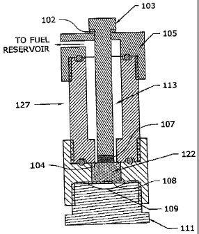
[0065] Fig. 1 shows an exemplary hydrogen generating apparatus 127. Apparatus
or
cartridge 127 includes a portion of solid fuel component 107 held in a chamber
adjacent a
chamber filled with a liquid fuel component 122. Either fuel component may be
any fuel
- 12 -
CA 02611019 2014-02-04
WO 2006/135895
PCl/US2006/023024
component described herein, such as using sodium borohydride for solid fuel
component 107
and water, catalyst and additives as liquid fuel component 122. Solid fuel
component 107
and liquid fuel component 122 are separated by a thin frangible membrane 104.
A rod 103 is
in contact with solid fuel component 107, extends through a fuel conduit 113,
and out of
apparatus 127 through a cap 105. Rod 103 can move toward solid fuel component
107 a
small amount when impacted by a sufficient force. 0-ring 102 cushions the
impact and seals
the aperture. When rod 103 is struck, rod 103 pushes solid fuel component
through frangible
membrane 104 into liquid fuel component 122. A void 109 may also be provided
below
liquid fuel component 122 and separated therefrom by a flexible membrane 108,
such as a
thin sheet of rubber or urethane. Void 109 allows the greater volume of liquid
fuel
component 122 due to the addition of solid fuel component 107 to expand
adequately. As
fuel components 107, 122 react, fuel gas is produced. The fuel travels through
fuel conduit
113 and out to a fuel reservoir (not shown) to replenish the fuel gas
therewithin. Apparatus
127 further includes a base portion 111.
10066] Other suitable gas generating apparatus usable with the fuels described
herein are
discussed in U.S. publication 2008/0206113 and U.S. patent 7,896,934, which
were filed on
the same day as the provisional application entitled "Fuels for Hydrogen
Producing
Cartridges," having serial number 60/689,572, also filed on June 13, 2005,
which issued as
U.S. patent no. 8,636,961. The present application claims priority to the '572
provisional
application.
[0067] Other suitable gas generating apparatus include those described in
commonly owned
United Stales patent application publication number 2005/0074643, and U.S.
patent nos.
7,481,858 and 8,002,853.
100681 Another suitable gas generating apparatus is illustrated in Figs. 2 and
3. As shown,
gas generating apparatus 200 has housing 202, which is generally cylindrical.
However,
housing 202 can have any shape. Housing 202 is connected to sealing end cap
204 on one
end and to end cap 206 at the other end, as shown. End cap 206 defines flow
channel 208 to
allow the hydrogen gas produced within apparatus 200 to flow to a fuel cell
(not shown).
Channel 208 is fluidly connected to a shut-off valve 210 to control the flow
of hydrogen out
of the apparatus. When valve 210 is turned off, apparatus 200 is sealed. Any
shut-off valve
can be used. Suitable shut-off valves include those described in commonly
owned United
States patent application publication numbers 2005/0022883 and 2005/0116190,
and in
- 13-
CA 02611019 2014-02-04
WO 2006/135895
PCT/US2006/023824
commonly owned ti.S. patent no. 7,762,278, U.S. publication nos. 2006/0071088
and
2008/0233457.
100691 Within housing 202 is disposed fuel carrier 212, which in a preferred
embodiment is
fixed relative to housing 202. Fuel carrier 212, as shown in Fig. 3, has a
profile of a cross
with one of the four orthogonal segments carrying a plurality of fuel capsules
or ampoules
214. Fuel carrier 212 can have any shape or profile, as long as fuel carrier
212 has openings
to allow the produced hydrogen gas to flow toward end cap 206 and channel 208,
and to
allow the produced gas to exert pressure on automatic shut-off mechanism 216,
as described
below. Such openings can he spaces 218 between the orthogonal segments of the
cross
profile shown in Fig. 3. Also, as illustrated, fuel capsules 214 are carried
by only one of the
four orthogonal segments. However, fuel capsules 214 can by carried by any
portion of the
fuel carrier 212 and can be carried by all the segments of fuel carrier 212.
100701 Each fuel capsule 214 comprises a solid fuel component 107 and a liquid
fuel
component 122 separated by membrane 104, similar to those in gas generating
apparatus 127
shown in Fig. 1. Once membrane 104 is torn or otherwise ruptured, the solid
and liquid
fuels/reactants arc mixed to produce hydrogen, as described above. The amounts
of liquid
and solid fuels are pre-measured or pre-determined to maximize the hydrogen
produced, also
as described above.
[NM Fuel carrier 212 also includes coil spring 220. One end of coil spring 220
is located in
pocket 222 of shut-off mechanism 216, and coil spring 220 extends to connect
to membranes
104 in all fuel capsules 214. As assembled, coil spring 220 is pre-loaded, so
that it has a
tendency to coil into pocket 222_ As the spring coils, it ruptures membranes
104 and the fuel
capsules 214 sequentially by hooks or similar devices, until the coiling
action is stopped or
when the spring fully recoils into pocket 222.
10072] Shut-off mechanism 216 has flexing arm or arms 224. Arm 224 defines
slot 223, and
fuel carrier 212 has extension 225 which carries pin 225a. Pin 225a is
received in slot 223, so
that when shut-off mechanism 216 is moved toward end cap 204, arm 224 is
flexed
downward, When shut-off mechanism 216 moves away from end cap 204, arm 224 is
flexed
upward. When arm 224 is sufficiently flexed downward toward the coils of
spring 220 in
pocket 222, it touches or contacts the spring to arrest the coiling action,
10073] Shut-off mechanism 216 is spaced from end cap 204 by spacing 226, which
is filled
with a gas or a compressed gas, such as air, nitrogen or hydrogen. The gas 227
in spacing
226 acts like a gas spring. When hydrogen is produced faster than it can be
consumed or
-14-
CA 02611019 2014-02-04
WO 2006/135895 PCS/TJS2006/023024
when valve 210 is closed, the internal pressure inside housing 202 increases.
This pressure
acts on shut-off mechanism 216 tending to push it toward end cap 204 against
gas spring 227.
When this internal pressure exceeds a predetermined threshold, arm 224 presses
on coil
spring 220 to stop the coiling action and the rupturing of membrane 104.
Hence, the
production of hydrogen stops. When valve 210 is opened, the hydrogen gas is
transferred or
produced from housing 202, thereby reducing the internal pressure in gas
generating
apparatus 200. As the internal pressure is decreased, gas spring 227 pushes
shut-off
mechanism away from end cap 204 and arm 224 is moved away from coil spring 220
to
allow the coiling action to resume.
100741 In this embodiment, shut-off mechanism 216 automatically stops the
production of
gas by stopping the reactions caused by the rupturing of additional membranes
104, when the
internal pressure of gas generating apparatus 200 reaches a predetermined
threshold. When
the internal pressure drops below this threshold, the shut-off mechanism
automatically allows
the production of gas to resume by continuing the rupturing of membranes 104
of unreacted
fuel capsules 214.
[0075] Gas spring 227 Can be replaced by other springs, such as helical
springs, compressed
foams or other springs. Advantageously, gas generating apparatus 200 contains
only two
moving parts, i.e., shut-off mechanism 216 and coil spring 220. Also, when gas
generating
apparatus 200 is first assembled or before the first use, the gas generating
apparatus 200 can
be charged with a pressurized gas, such as hydrogen, to activate shut-off
mechanism 216 to
prevent coil spring 220 from recoiling until a user opens valve 210 for the
first time.
Additionally, pocket 222 can be formed separately from shut-off mechanism 216,
so that this
pocket remains stationary when the shut-off mechanism moves.
[00761 Other embodiments of the present invention will be apparent to those
skilled in the art
from consideration of the present specification and practice of the present
invention disclosed
herein. While embodiments of the invention have been described in the detailed
description,
the scope of the claims should not be limited by the preferred embodiments set
forth in the
examples, but should be given the broadest interpretation consistent with the
description as a
whole.
- 15 -