Note: Descriptions are shown in the official language in which they were submitted.
CA 02611342 2007-11-21
2006P22353EP 01
1
Description
Method of handling wind turbine blades and device for
mounting wind turbine blades, in particular mounting blades
on a wind turbine
The invention relates to methods for handling wind turbine
blades and mounting said blades on a wind turbine. The
invention further relates to a wind turbine blade lifting
device as well as to a wind turbine blade lifting system.
Modern wind turbines usually comprise a rotor with
considerable diameter and width. Mounting a wind turbine
could include the steps of transporting the different
elements to the site of the wind turbine, assembling the
tower sections and the tower, lifting the wind turbine
nacelle with a crane and mounting the nacelle on the top of
the tower, assembling the wind turbine rotor on the ground,
lifting the wind turbine rotor with a crane and mounting the
rotor to a low speed shaft extending from the nacelle.
The usual way comprises a number of difficulties which have
become more and more severe with the increasing size and
width of the wind turbine rotor. In particular, assembly of
the wind turbine rotor on the ground is difficult as it
requires a large area to be free of obstacles which is
substantially horizontal and stable in order to be accessible
for the assembly workers and the crane. Furthermore, lifting
the rotor to the nacelle is rather complicated as the rotor
must be turned by 90 in midair. In other lifting systems it
is known to pre-mount the wind turbine hub on the nacelle and
then lift each wind turbine blade successively to position it
next to the hub and perform the mounting of the blades. Such
a system is, for example, described in US 2006/0120809 Al
where the blades are mounted in horizontal orientation, and
in US 2006/0147308 Al where the blades are mounted in
vertical orientation. A gripping device for lifting wind
CA 02611342 2014-04-01
4 10 6-34 3
2
turbine blades in a vertical orientation which comprises two
clamping jaws is disclosed in US 2005/0019166 Al.
In such systems it is often difficult to release a lifting
device from the blade once the blade was mounted to the rotor
hub. Some systems require that personnel ascend the lifting
device and manually disengage the device from the blade.
Other systems rely on the blade being kept in place in
lifting the lifting device purely by gravity. After mounting
the blade on the rotor hub the device is lowered so that it
can be released from the blade width and is then moved
-horizontally towards the blade tip until it is free of-the -
blade. This requires very skilled crane operation, however,
and when carrying out the installation during high wind
damage to the blade may occur.
Considering this prior art, it is an objective of the present
invention to provide an improved method of handling a wind
turbine blade and mounting said blade on a wind turbine hub.
It is a further objective to provide an advantageous wind
turbine blade lifting device and an advantageous wind turbine
blade lifting system.
The first objective is solved by a method of handling a
wind turbine blade and mounting said blade on the wind
turbine hub. The second objective is solved by a wind
turbine blade lifting device and by a wind turbine
blade lifting system.
The inventive method of handling a wind turbine blade and
mounting said blade on a wind turbine hub located at a
nacelle at the top of a wind turbine tower comprises the
steps of a) lifting the wind turbine blade with a lifting
system for handling wind turbine blades, in doing so said
wind turbine blade being oriented in a substantially
horizontal position; b) fixing the wind turbine blade in the
CA 02611342 2007-11-21
2006P22353EP 01
,
3
substantially horizontal position to the wind turbine hub; c)
releasing the lifting device from the blade using a remote
control unit; and d) removing the lifting device from the
blades. In particular, the orientation of the blade may be
kept in a substantially horizontal direction after the blade
is lifted off the ground. Keeping the blade in a
substantially horizontal direction during installation can be
realised by control wires by which the orientation of the
blade can be influenced. In addition, the method may further
include, as a preceding step, a step of lifting a wind
turbine hub to a nacelle of a wind turbine with a lifting
system and mounting the hub on the nacelle or lifting the
wind turbine hub and the nacelle together with a lifting
system and mounting the nacelle including the hub on a wind
turbine tower.
With the inventive method it becomes possible to handle and
mount a wind turbine blade in an advantageous manner. Since
during lifting the blade from the ground and mounting the
blade to the hub the blade is in a substantially horizontal
position it is not necessary to turn the blade during the
lifting process. Moreover, since releasing the lifting
device from the blade is done by using a remote control unit
it is not necessary for personnel to ascend to the lifting
device to manually disengage the device from the blade.
For performing the method a remotely controllable and
releasable lifting device may be used for orienting as well
as for fixing the blade during installation.
An inventive wind turbine blade lifting device comprises a
lifting frame for receiving a wind turbine blade and a
clamping device with a remotely controllable release
mechanism. The remotely controllable release mechanism may,
in particular, be used for releasing a wind turbine blade
from the lifting frame once it is installed on a wind turbine
hub. The remotely controllable release mechanism facilitates
the dismounting of the lifting device from a wind turbine
CA 02611342 2007-11-21
2006P22353EP 01
4
blade once it is fixed to the hub as no personnel need to
ascend to the lifting device.
In the inventive lifting device the clamping device may
comprise a seat arranged at the frame which is designed such
that a wind turbine blade can be pressed towards it with its
trailing edge, its leading edge, its pressure side or its
suction side. It then further comprises at least one belt or
strap which is designed such that it can be wound around the
blade and fixed to the frame. The flexibility of a belt or
strap offers the possibility of using the same lifting device
for various kinds of turbine blades which may vary, e.g. in
thickness and/or cord length.
The clamping device may further comprise a gripping
arrangement which is arranged and designed for gripping at
least one end of the at least one belt so as to fix the end
to the frame. In addition, the clamping device may comprise
a tightening arrangement which is arranged and designed for
tightening the at least one belt so as to press the blade
towards the seat. In particular, one end of the at least one
belt may be permanently fixed to the frame at one side of the
seat and the tightening arrangement may be located at the
other side of the seat. The gripping arrangement may, in
particular, be part of the tightening arrangement.
Furthermore, the tightening arrangement may be part of the
release mechanism. The release mechanism may comprise a
mechanism for releasing the tightening action of the
tightening arrangement. In this case dismantling the lifting
device from the blade can be realised by just letting the at
least one band or strap slip out of the gripping arrangement.
Complicated constructions in the release mechanisms are not
necessary.
The lifting device may be lowered onto the blade while the
blade is resting on the ground. Then the frame will be
attached to the blade using the belt or belts that is/are,
for example, permanently attached to the frame on one side.
CA 02611342 2007-11-21
2006P22353EP 01
From the side of the blade at which the belt is attached to
the frame the belt may run below the lower part of the blade
and then be clamped in the release mechanism on the frame
side which is located at the other side of the blade. After
5 tightening the belt or belts (in case two or more belts are
used) the blade is securely fixed to the lifting device and
can be lifted by the use of a crane.
When the release mechanism comprises a remote control unit
for remotely controlling the release of the tightening action
the belt or belts can be loosened by the remote control so
that the side of the belt which has been gripped by the
gripping arrangement can slip out. As a consequence, the
lifting device can be easily lifted off the blade when the
blade is in a horizontal position. The release mechanism can
be remotely controlled by the crane operator by suitable
means, e.g. hydraulically, electrically, by wire pull, etc.
The ability to remotely release the lifting device once the
blade is fitted to the rotor hub is advantageous as it
eliminates any need for personnel to ascend the lifting
device at great height. Compared to systems where the blade
is resting in the lifting device purely by gravity, the
demanding lowering and horizontal movement of the lifting
device is eliminated.
The tightening arrangement may be an independent device or it
may be part of the release mechanism.
It is particularly advantageous if the clamping device
comprises at least two belts or straps which are designed
such that they can be wound around the blade and fixed to the
frame. Pressing the blade to the seat at two different
locations offers the opportunity to use bands or straps which
may have a considerably smaller width than with using only
one band or strap. One band or strap needs to be
sufficiently broad in order to ensure that the blade does not
tilt towards a vertical orientation during the lifting
process.
CA 02611342 2014-04-01
54106-343
6
An inventive wind turbine blade lifting system comprises an
inventive wind turbine blade lifting device and a crane boom.
The lifting device is connected to the crane boom via control
wires for controlling the blade orientation in a substantially
horizontal position when it has been lifted off the ground. It
may, in particular, further comprise a holding wire which bears
the main part of the blade's weight when it is lifted off the
ground.
According to one aspect of the present invention, there is
provided a wind turbine blade lifting device comprising a
lifting frame for receiving a wind turbine blade and a clamping
device with a release mechanism, wherein the release mechanism
is remotely controllable and the clamping device comprises:
seat arranged at the frame which is designed such that a
turbine blade can be pressed towards it with its trailing edge,
its leading edge, its pressure or its suction side; and at
least one belt which is designed such that it can be wound
around a blade and fixed to the frame; and a tightening
arrangement which is arranged and designed for tightening the
at least one belt so as to press the blade towards the seat;
and the tightening arrangement is part of the release
mechanism; and the release mechanism comprises a mechanism for
releasing the tightening action of the tightening arrangement;
and the release mechanism comprises a remote control unit for
remotely controlling a release of the tightening action.
CA 02611342 2014-04-01
54106-343
6a
Further features, properties and advantages of the present
invention will become clear from the following description of
an embodiment of the invention in conjunction with the
accompanying drawings.
Figure 1 shows an embodiment of the inventive wind turbine
blade lifting device.
Figure 2 shows attaching a wind turbine blade to the lifting
device.
Figure 3 shows a wind turbine blade attached to the lifting
device.
Figure 4 shows the mounting of a wind turbine blade to a
rotor hub of a wind turbine.
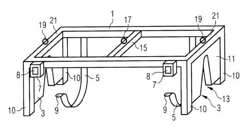
An inventive wind turbine blade lifting device will now be
described with respect to Figure 1. The lifting device
comprises a lifting frame 1 with a clamping device and a
remotely controllable release mechanism. The clamping device
comprises two seats 3 which are designed such that a turbine
blade 23 can be pressed towards it with its trailing edge 25
(Figure 2). It further comprises two belts 5 which are
located at the frame I close to the seats 3 and which can be
wound around the wind turbine blade 23 after the frame is
lowered to the blade 23 with the seats 3 on the blade's
trailing edge 25. One end of each belt 5 is permanently
CA 02611342 2007-11-21
2006P22353EP 01
7
fixed to the frame 1 while the other end can be fitted into a
combined gripping and tightening arrangement 7 which is fixed
to the frame 1 on the side of the frame 1 which is opposite
the side to which the belts are permanently fixed. For
securing the blade 23 to the frame 1, the loose ends 9 of the
belts 5 are inserted into the gripping and tightening
arrangement 7 where they are then tightened and secured
against slipping out. In the present embodiment the gripping
and tightening arrangement 7 is realised as a remotely
controllable ratchet device which can, in particular, be
unlocked by a remote action so that the ends 9 of the belts 5
can easily slip out of the ratchet mechanism, i.e. out of the
gripping and tightening arrangement 7. The remote control
unit for remotely unlocking the ratchet mechanism 7 is
indicated by block 8 in Figures 1 and 2.
The seats 3 are realised by a flexible element 11, e.g.
rubber elements, located between legs 10 of the frame 1.
They have openings 13 which are adapted to the shape of the
trailing edge 25 of the wind turbine blade 23 to be lifted.
However, the seats could, in principle, instead have openings
which are adapted to the shape of the blade's leading edge,
its pressure side or its suction side.
At a central crossbar 15 of the frame 1 a ring 17 is mounted
to which a wire 33 (Figure 4) for bearing the weight and the
lifting device and the blade attached thereto can be fixed.
Second rings 19 are present at outer crossbars 21 of the
frame 1 to which control wires (31) can be fixed for
controlling the orientation of a blade attached to the
lifting device.
The lifting device is attached to a wind turbine rotor blade
23 when the blade 23 rests on the ground. The blade 23 rests
such that its trailing edge 25 shows upwards. After lowering
the frame such that the flexible elements 11 come to a rest
on the blade's trailing edge 25 the belts 5 are wound around
the blade's leading edge 27, then the loose ends 9 of the
CA 02611342 2007-11-21
2006P22353EP 01
8
belts 5 are introduced into the ratchet mechanism 7 and then
the belts 5 are tightened. At the same time the ratchet
mechanism locks so as to prevent the belts 5 from slipping
out of the ratchet mechanism if not an explicit release or
unlocking operation is performed by remote control. Hence,
the blade 23 is firmly fixed to the frame 1 of the lifting
device by tightening of the belts or straps. The tightening
arrangement may be independent, or it may be part of the
release mechanism, as it is in the present embodiment.
Figure 3 shows a section through the wind turbine blade 23
after it has been attached to the lifting device.
Figure 4 shows a wind turbine blade 23 when it is being
mounted on a rotor hub 9 of a wind turbine. The blade 23
which is shown to be mounted to the hub 29 in Figure 4 is the
last blade of the rotor to be mounted. When mounting the
blade the rotor hub is rotated such that the blade 23 can be
mounted in a horizontal position. By mounting the blade in a
horizontal position it is not necessary to rotate the blade
during lifting it to the hub 29. During the lifting process
the horizontal orientation of the blade can be controlled by
control wires 31 which are fixed to the rings 19 at the outer
crossbars 21 of the frame 1. The weight of the blade 23 and
the lifting device are carried by a central holding wire 33
which is fixed to the ring 17 at the central crossbar 15 of
the frame 1. All three wires are carried by a crane boom 35
which is used to lift the blade off the ground and to bring
it into a position which is suitable for mounting it on the
rotor hub 29.
After the rotor blade 23 is fixed to the rotor hub 29 a
remote control signal is sent to the remotely controllable
ratchet mechanism 7 for unlocking it so as to release the
gripping and tightening force of the ratchet mechanism 7.
After releasing these forces the belts 5 to slip out of the
ratchet mechanisms 7 and the frame 1 can easily be lifted off
the blade 23. Even if the belts 5 do not fully slip out of
the ratchet mechanisms 7 after the unlocking control signal
CA 02611342 2007-11-21
2006P22353EP 01
9
has been sent they will do so when the frame 1 is lifted off
the blade since they are no longer held by the ratchet
mechanism 7. The control signal may be sent by the crane
operator which has the advantage that the whole dismounting
action is controlled by a single person so that no
coordination between different persons is necessary.
However, it would also be possible that the release control
signal is sent by another person, for example the person who
is responsible for fixing the blade to the hub 29.
Although a special embodiment has been described with respect
to the figures, deviations of this embodiment are possible.
For example, the number of belts is not restricted to two.
More or less than two belts are also possible. However, if
only one belt is used the belt should be rather broad. It
could, for example, extend over the whole distance between
the outer crossbars 21. If more than one belt is used it is
not necessary that the gripping and tightening arrangement 7
is located at the same side of the frame for each belt. In
addition, it may even be possible to have belts which are not
permanently fixed to the frame 1. In this case a further
gripping and tightening arrangement or at least a further
gripping arrangement would be present at the frame 1 for each
belt 5.
The release control signal could be sent to the gripping and
tightening arrangements 7 either wirelessly or by a signal
wire which could extend from the crane boom to the frame 1.
In addition to the release action also the tightening action
could be triggered by a remote signal.
Although seats are only present at the outer crossbars in the
present embodiment further seats could be present as well.
For example, a third seat could be present at the central
crossbar 15.
In any case, the rotor hub 29 is mounted to the nacelle of a
wind turbine before the wind turbine blades 23 are mounted on
CA 02611342 2007-11-21
2006P22353EP 01
the rotor hub. Mounting the rotor hub 29 on the nacelle can
either be done before or after mounting the nacelle at the
tower top of the wind turbine. When the rotor hub 29 is
mounted on the nacelle after mounting the nacelle to the
5 tower top a crane will be used for lifting the rotor hub to
the nacelle. This crane may be the same crane which will
later be used for mounting the wind turbine blades 23 on the
rotor hub 29. In case the rotor hub is mounted on the
nacelle before the nacelle is mounted on the tower top the
10 nacelle will be lifted to the tower top by the crane together
with the already mounted hub by use of a crane which can
later be used for mounting the blade 23 on the rotor hub 29.