Note: Descriptions are shown in the official language in which they were submitted.
CA 02611424 2015-03-04
-1-
Title: A METHOD AND SYSTEM FOR DISTRIBUTING ENERGY
FIELD OF THE INVENTION
This invention relates generally to the field of energy distribution
and more particularly to the field of distribution of electrical energy in an
energy distribution network or power grid.
BACKGROUND OF THE INVENTION
Electricity is currently distributed through a wholesale electrical
transmission network or power grid. Typically, the network is operated at
a higher voltage than the standard voltage for retail consumption.
Electricity may be generated at various locations on the grid by various
types of power sources, including nuclear generators, coal-fired and gas
driven generators, and hydro electric generators, from where it flows
across the grid to centres of demand which include retail distribution
operations of for example, local utilities that transmit the electricity onto
retail customers, utility operations that distribute electricity to industrial
or
large commercial customers, or to such large industrial or large
commercial customers directly. The form of electrical power that is
transmitted over the long distance portions of the grid is alternating
current (AC) at high voltage and it is stepped down to progressively lower
voltages as it approaches a portion of the grid where it is to be consumed
by the end user. An alternative form of current is high voltage direct
current (HVDC) which must be inverted back to AC before distribution to
the end user. The electricity is directed over a series of electrical wires,
supported by power pylons and hydro poles and is often collectively
referred to as the power grid. Significant line losses are a feature of such
systems.
The development of the grid is often organic in nature. When
power supply, power demand and transmission capacity grow at different
rates in different locations the potential arises for an excess of supply or
CA 02611424 2015-03-04
-2-
demand with an insufficient transmission capacity to move the electricity
from one location to another. Changing population demographics and
industry locations exacerbate this problem over the long term. Local grid
expansion due to local utility planning, and regional grid control, in the
form of regional independent system operators also contributes to a lack
of a co-ordinated overall design. The change in
the location of
consumption and in the location of power generation can result in
congestion in the grid at certain points, which can prevent a load centre
from receiving enough power. Typically, in North America, this
congestion is regional since the wholesale grid is comprised of a relatively
small number of large transmission lines. Thus a bottleneck at one
location results in supply issues for much of the area on the demand side
of the bottleneck (i.e. a big city) that is unable to readily access power
from another main transmission line being too remote therefrom. One
means currently used for resolving congestion is to allow the market to
place a price on the power traversing in the congested region on the grid.
During periods of greater demand, a higher price can be obtained for the
sale of the power through that bottleneck. The higher price can provide
the signal for a degree of demand curtailment.
Electrical demand fluctuates during the day with peaks most often
occurring from 8:00 to 10:00 AM and from 5:00 to 8:00 PM. On the other
hand, certain types of low cost power generation are more efficient when
operated on a continuous basis and other more expensive forms of power
generation can be operated in response to peaks and demand. The low
cost types of power generation have historically been less attractive to
locate sites near population centres (which are typically also demand
centres) due to transportation costs associated with the fuel used to
generate the electricity, concerns about pollution, and fear of locating
nuclear plants near population centres. In the absence of congestion at
specific bottlenecks, prices near to low cost generation and a distant load
centre are similar but with congestion, and a local excess of demand over
CA 02611424 2015-03-04
-3-
supply, price differences can expand significantly. As a result, electricity
prices are both time dependent and location dependent in the current
power grid. Construction of additional transmission capacity is often not
an easy, cost effective or adequate solution to reducing congestion
because of the uncertainties of future demand. If new routes are
required, then it can be very difficult and expensive to secure the
necessary land rights to establish an easement to run the power lines.
Different sections of the grid may be operated by different entities
called Independent System Operators. This exacerbates the problems of
maintaining an overall grid design as the grid tends to be designed in a
piecemeal fashion. The grid operators use several means to control the
quantity, quality and stability of the power being transmitted so that the
supply is reliable for the customer. The quantity of power transmitted is
managed by a system of scheduling and coordinating power transactions
between suppliers and consumers which includes managing congestion
and/or providing a marketplace whereby rights to traverse a congested
part of the grid are exchanged. The quality of power is also in part
managed by having generators provide reserves of generation that can be
called into service at short notice. The quality of power, in particular the
frequency of AC current on the grid, is managed by having suppliers
provide spinning reserves that can be called upon instantaneously to help
adjust the frequency of the power on the grid or to replace off frequency
power supplies. Finally, grid operators also manage the voltage of the AC
current on the grid through the provision of voltage support by suppliers to
the electrical grid.
Included among these power management strategies are for
example, the known technique of peak shaving. In peak shaving,
adjacent to a congested location, electricity may be drawn off the grid and
locally stored during a low demand period, and then released from that
location during a high demand period. Excess demand which is unable to
be met due to the congestion at the transmission bottleneck can be met
CA 02611424 2015-03-04
-4-
with a boost of locally stored power. While providing an interim or
temporary solution, this approach of time shifting does not adequately
address the full dynamic nature of the need to match demand to supply
through the congested infrastructure of the power grid. As demand
grows, the problem of congestion becomes ever more of a concern, a
constraint on efficient distribution of electrical power, and inevitably a
higher cost to the end user.
As well, as newer renewable resources of energy are tapped, they
may be located in sites which are remote from conventional power grids.
Indeed, for wind farms and the like, being remote is often preferred.
Efforts exist in the prior art to resolve power grid issues. For
example, US Patent 5,610,802 describes an energy storage system which
is in a housing having a number of doors and internal racks. Battery
modules are placed on the racks and the storage system has an energy
storage capacity of 100kw, and a footprint of less than 400 square feet.
This patent describes how the energy storage system is transportable and
can be deployed to specific locations to deliver a power boost to a system
that is stressed, for example, by extreme cold weather.
However, referring to column 15, fine 55 this patent teaches that
the batteries be removed and transported separately from the housing
during transportation, to reduce the shipping weight of the storage
system. It is also contemplated that the batteries be shipped dry, and that
the electrolytes be shipped later. So, this patent teaches moving the
housing, moving the battery cases separately from the housing and then
moving the electrolytes separately from the rest. In other words the
invention can be moved from place to place, but is intended to be charged
from and discharged at the same location. As such it cannot deal with
bottlenecks in the electrical grid.
US Patent 6,026,349 is interesting because it teaches ways to
convert and store energy other than through electricity (i.e. compressed
gas). However, in this invention teaches locating the storage/discharge
CA 02611424 2015-03-04
-5-
facility at the margins of two adjacent power grids, so the energy can be
removed from or added to either adjacent grid. The purpose of this
invention is to permit specific power conditioning, suitable for either one or
the other grid to be performed, to permit the stored power to be released
to the power matched grid. However this stationary storage plant cannot
be used to for example overcome local bottlenecks in either of the
adjacent power distribution grids.
US Patent 6,900,556 is also interesting in teaching the use of
capacitors to temporarily store electrical energy. In this patent they
teach using a large-scale, capacitor-based electrical energy storage and
distribution system capable of effectuating load-leveling during periods of
peak demand on a utility, and of effectuating a cost savings associated
with the purchase of electrical energy. In a stationary or fixed plant
location (for a matter of days or weeks) embodiment a capacitor or
multitude of capacitors may be charged with electrical energy produced
by the utility, such as during periods of low demand or low cost, and
discharged during periods of high electrical energy consumption or high
electrical energy cost. One or more capacitors may be located at a
consumer's residence or business. Alternatively, a farm of capacitors may
be provided at or near a utility, or at or near a location experiencing high
demand.
In another embodiment, one or more capacitors may be located in
or on a vehicle, such as an automobile, a truck, or a train of a light rail
system.
In this embodiment the patent teaches using the stored energy on
the vehicle, to drive the vehicle from place to place, for example to permit
a light rail line which does not need a power transmission line along its
length, therefore reducing the capital cost of the transportation system.,
(see column 11, lines 5 to 8). In some cases the electrical energy can be
applied to a load in the source, but applying the energy to a load does not
overcome bottle necks in electrical distribution networks, by making more
CA 02611424 2015-03-04
-6-
electricity available on the other side of a bottleneck, which would require
power conditioning means to make the electrical energy suitable for
adding to the grid at that point. Furthermore, by consuming electrical
energy to drive the vehicle, there will be little left over to provide at the
load.
Other prior art patents of general interest in power storage and
energy distribution include US Patents 3,682,704; 5,439,757; 5,798,633;
6,475,661; 6,649,289; 6,653,749; 7,199,550; and U.S. Publication No.
2004/0197649.
What is desired is a form of resolving problems of getting electricity
from a location where it can be generated at a low cost, and delivering the
electricity beyond the congestion bottlenecks or infrastructure gaps to
where it can be sold for a high price. What is required is a way of
providing such electricity which is dynamic and can be adapted for
changes in the demand location over time without requiring expensive
capital improvements to the existing grid, without requiring new expensive
right of ways, and without exposing people to more incident electro-
magnetic fields associated with high tension electrical wires.
SUMMARY OF THE INVENTION
Accordingly, the present invention is directed to a method of
distributing electrical energy to a point in an electrical grid without the
electricity going through the electrical power grid to get to the point. The
present invention also comprehends a distribution system for achieving
such power distribution.
Therefore according to a first aspect the present invention provides
a method of delivering electrical energy to a point in an electrical power
grid, said method comprising the steps of:
accessing a source of energy at a first location;
converting said energy into a form of transportable energy;
CA 02611424 2015-03-04
-7-
transporting said transportable energy from said first location
having said source of energy to said point on said electrical power grid at
a second location having a need for additional electrical power without
said transportable energy going through said electrical power grid to said
point;
converting said form of transportable energy into electrical energy
and
discharging said electrical energy into said power grid at said point.
According to a further aspect the present invention provides a
method of distributing electrical energy to a point in an electrical grid
without said electricity going through said electrical grid to said point, as
claimed in claim 1 wherein said step of converting said energy into a form
of transportable energy comprises changing an electrochemical potential
of both a positive and a negative liquid electrolyte at a charging station
connected to said source of electrical energy;
said step of transporting said transportable energy comprises
transporting said liquid electrolytes from said first location to said second
location and said step of converting said form of transportable electrical
energy comprises placing said liquid electrolytes in a discharging station
at said point in said electrical grid at said second location; and
discharging electricity to said point through said discharging
station.
According to a further aspect the present invention provides a
distribution system for distributing electricity around, but not through, a
power grid said distribution system comprising:
a first compressor connected to a source of power at a first location
to store energy by compressing air into a compressed air storage
container; and
a means for transporting said compressed air storage container to
and from said first location compressor;
CA 02611424 2015-03-04
-8-
a second means for converting compressed air into electrical
energy connected to said electrical power grid at a second location for
receiving said compressed air from said first compressor;
a means for transporting said compressed air storage container to
and from said second location, and between said first and said second
locations;
wherein said distribution system permits electrical power to be
added to a point in the power grid without being transmitted through said
grid to said point.
According to a further aspect the present invention provides a
distribution system for distributing electricity around, but not through, an
electrical power grid, said distribution system comprising:
a charging station connected to a source of power at a first location
to convert electrical energy into a form of transportable energy;
a means for transporting said transportable energy from said first
location to a second location;
a discharging station at said second location connected to said
electrical power grid to convert said transportable energy back into
electrical energy; and
an electrical connection between said electrical power grid and
said discharging station to permit said electrical energy to be discharged
into said electrical power grid at said second location.
BRIEF DESCRIPTION OF THE DRAWINGS
Reference will now be made, by way of example only, to preferred
embodiments of the invention, in which:
Figure 1 is a schematic of a power grid;
Figure 2 is a price vs. time plot for two points, A and B in the power
grid of Figure 1;
Figure 3 is a plot of the price difference between the points A and B
of Figure 2;
CA 02611424 2015-03-04
-9-
Figure 4 is a schematic of a charging and a discharge arrangement
according to one embodiment of the present invention;
Figure 5 is a transportable container according to one aspect of the
present invention;
Figure 6 is a transportable container according to a second aspect
of the present invention;
Figure 7 is a transportable container according to a further aspect
of the present invention;
Figure 8a is a view of a network arrangement according to the
present invention;
Figure 8b is a pricing table for wholesale electrical energy for
different times and places in the transportation network of Figure 8 a;
Figure 9 is a transportable storage container for a thermal storage
fluid according to a further aspect of the present invention;
Figure 10 is a transportable storage container for a phase change
thermal storage material according to a further aspect of the present
invention;
Figure 11a is an example of one format of transportable energy
conversion equipment according to the present invention;
Figure llb is an example of a second form of transportable energy
conversion equipment according to the present invention; and
Figure 11c is an example of a third form of transportable energy
conversion equipment according to the present invention.
DETAILED DESCRIPTION OF THE PREFERRED EMBODIMENTS
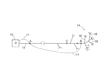
Figure 1 shows a schematic of a portion of a power grid system. At
the left hand side a source of power 10, which might be any conventional
source of power such as a coal or gas fired power plant, nuclear plant,
wind farm, hydro electric dam of the like. Adjacent to the source of power
10 and located on the power line 12 is a grid point A. The power line 12
extends typically a significant distance across a series of power grid
CA 02611424 2015-03-04
-10-
sections (not shown) eventually, the power line 12 ends up adjacent to a
high load or heavy demand district 14. This is illustrated by a plurality of
branches 16 which extend from the power line 12 within the area 14. Also
shown is a second grid point B adjacent to the high demand area 14. Also
shown is a dashed line 11, which is explained in more detail below.
Electricity produced at the source of power 10 passes through grid
point A on the power line 12. Eventually the power reaches grid point B
adjacent to the demand area 14 still on the power line 12. As can be
appreciated, the demand for electricity at point B adjacent to the demand
area 14 will be significant. In the event that the demand in area 14 grows
in size beyond that which can be easily transmitted to point B, for example
by reason of a capacity limit or constraint on the power line 12 at point C,
there may be a shortage of supply of electricity which can pass through
point C to meet the demand in area 14 past point B. In this circumstance,
the price of power will rise and a certain rationing of power consumption
will occur in the area 14 by reason of the higher price.
In contrast, at power grid point A, there is little local demand
meaning that the power being transported along the line 12 is generally
always sufficient to meet the small amount of change of local demand.
Thus, the price fluctuations for power over a 24 hour period at point A are
much less than those experienced at point B because power demand is
not in excess of the power carrying capacity of the grid at that point.
Figure 2 shows a graph in which the price of the electricity charged
to customers at point B, past the line capacity constraint at point C, is
shown with Line B and the price to customers at point A is shown at Line
A over a typical 24 hour period. The absolute values will of course
fluctuate over time, from year to year and the like. What is relevant to this
invention is the cost pattern, rather than the specific cost amounts. As
can be seen from the power price curve, two price peaks occur in the cost
of the electrical power, one in the morning between approximately 6:30
AM and 11:30 AM and a second one occurs beginning at approximately
CA 02611424 2015-03-04
-11-
2:30 PM and the costs rise until a peak is reached at around 6:30 PM.
Then, power cost declines over time until it reaches a minimum around
10:30 PM. This pattern is true for both grid points A and B. It will now be
understood that even though the grid point A is located somewhat closer
or adjacent to the source of power 10, there will still be a price change
with time during each day with peaks 22 and 24 which are generally at or
about the same time as the peaks 16 and 18 for the power at grid point B.
There is a difference however in terms of the relative cost with the prices
at grid point B being significantly higher due to the larger local demand
and the bottleneck effect at point C of the transmission capacity limits of
power line 12.
Figure 3 plots the price difference between the power costs versus
time graphs of Figure 2. As can be seen, the relative costs vary
significantly between grid point A and grid point B over the typical 24 hour
cycle. It will be understood by those skilled in the art that the power cost
curves shown are illustrative in nature, and are not intended to reflect the
exact amounts of any specific location. However, the trends shown by the
graphs are believed to be generally representative of what occurs.
An aspect of the present invention is to take advantage of the price
differential between grid point A and grid point B at different points of the
daily price cycle. The present invention in one embodiment involves the
delivery of electrical energy, for example to grid point B, from electrical
energy extracted from at or about grid point A which electrical energy is
not delivered by means of power line 12. Thus, the present invention
comprehends delivering electrical power from grid point A to grid point B
without transmitting the power along the power grid or electrical power
line 12. The advantage of the present invention is therefore to avoid the
transmission bottleneck of the power grid located before point B at point
C. Thus, in addition to the time shifting of power delivery of the peak
shaving method of the prior art the present invention adds location
shifting.
CA 02611424 2015-03-04
-12-
As shown in Figure 1, the dashed line 11 illustrates the alternate
route for the energy according to the present invention. In some cases,
the source of power 10 does not generate electricity so the dashed line 11
represents getting the power from the power plant to the point A. From
there the energy, in the form of a transportable energy that can be readily
converted into electrical energy, is transported along route 11, to point B.
According to the present invention, there are two most preferred
ways of so delivering power along route 11. While these two most
preferred ways are discussed in detail below, it will be understood by
those skilled in the art that other ways of implementing the present
invention are also comprehended. In the first preferred embodiment of
the present invention, a charging device is used to change the electro-
chemical potential of a positive and negative electrolyte solution at the
location of grid point A. In other words, abundant and relatively low-cost
power is used to change the electro-chemical potential of the electrolytes
in a manner analogous to a flow battery.
Figure 4 shows the elements of a charging station 50 according to
the present invention. According to the present invention, a specific and
cost effective type of electrolyte charging and discharging arrangement
can be used to transport electrical energy from point A to point B in the
grid without necessarily going through the grid points namely, along route
11. More specifically, an electrolyte charging station illustrated at 50 in
Figure 4 can be provided at grid point A, where the cost of power is low.
In addition to being a lower cost source of power, charging can be time
modulated to ensure that the lowest price of power at grid point A is used.
The electrolyte charging station 50 consists of a source of grid power 52
which feeds into a power conversion system and high speed grid
connection controller 54. A rectifier 56 is provided to convert the power
from AC to DC.
Like a flow battery, the charging station 50 of the present invention
differs from a conventional battery in that the chemical reaction occurs
CA 02611424 2015-03-04
-13-
between two electrolytes rather than between an electrolyte and an
electrode, and the electrolytes are stored external to the electrode section
and are only circulated through the electro-chemical cell stack as required
to store electrical energy. As in a flow battery the charging station 50
uses an electrode that does not take part in the electrochemical reactions,
but merely serves as a substrate or a conductor.
The positive 58 and negative 60 electrolyte are circulated through
the cell stack 62 where the DC current is applied across the electrodes
64, 66 (not shown) to create an electro-chemical potential between the
two electrolytes. Ions pass across the membrane 68 to change the
electrochemical potential of the electrolytes. Banks of cells may be linked
together to create a bipolar module cell stack where the electrodes are
shared between adjacent cells with the cathode of the first cell becoming
the anode of the next cell and so on. Linked in series, sufficient cells in
the stack can then form the desired voltage for the cell stack. During
operation, the circulat:on control system causes the electrolytes to flow
from two separate storage tanks through the cell stacks. A negatively
charged electrolyte 60 and a positively charged electrolyte 58 are used on
opposite sides of the membrane. The electrolytes flow to the cell stack
where ions are transferred between the two electrolytes across the ion
exchange membrane 68. After the reaction, the electrolytes are returned
to separate storage tanks 70, 72. Most preferable these electrolytes are
placed into transportable storage containers 70, 72, for example, railway
tankers, for transportation to a second location, such as point B. The
amount of electricity transported, is directly related to the volume of
electrolyte that is being transported and the energy density of the
electrolyte used.
As will be understood by those skilled in the art, there are a
number of specific chemistries for the electrolytes, including, vanadium
redux, zinc bromine, polysulphide bromine, and cerium/zinc. One
advantage of an electrolyte charging system as described is that the
CA 02611424 2015-03-04
-14-
electrical storage capacity is related only to the liquid storage capacity of
the electrolyte storage reservoirs. The present invention takes advantage
of the external storage aspect of the electrolyte.
Located beyond the transmission bottleneck, at point C, is point B,
which has an electrolyte discharging apparatus 100, which is the
geographically remote second part of a first embodiment of the present
invention. It also has a cell stack 102, which may be characterized as a
discharging cell stack 102 (the right side of Figure 4). Most preferably the
charging and discharging locations are each located adjacent to a
convenient transportation corridor, such as a railway line, so that a train,
for example, can be used to haul the liquid electrolytes between point A
and point B, even though point A and B are geographically remote from
one another. At point B, the electrolytes 58, 60 can be passed through
the discharging cell stack 102 by a circulation control system so as to
pass ions across the membrane 104 and cause an electrical potential to
arise between the electrodes 106, 108 (not shown). An inverter 110 (DC
to AC) inverts the electrical power, and through a power conversion
system 112 and hign speed electrical grid connection controller the
electrical energy is dumped back into the grid. It will be appreciated that
after the electrolytes 58, 60 are circulated past the membrane 104, they
can be reloaded into the transportable containers 116, 118 for delivery
back to grid point A for recharging. The electricity is therefore provided or
made available beyond the transmission bottleneck C. This electricity can
be sold at a higher rate at point B than it was purchased for at point A and
can be used to alleviate supply issues arising beyond the bottleneck at C.
As can now be understood the time of discharge can be controlled to
optimize revenue, and the type of discharge can be controlled to achieve
power conditioning ends such as voltage support, frequency control
and/or spinning reserves.
The present invention comprehends that the facilities to extract
electricity at point A, then to add electricity at point B, be made with as
CA 02611424 2015-03-04
-15-
little cost as possible. Therefore, rather than building a complete flow
battery at each location A and B, the present invention comprehends
building an electrolyte charging station 50 at the low cost power site A,
and an electrolyte discharging station 100 at the higher priced location B.
Thus, while each location would require a circulation control system for
the liquid electrolytes 58, 60 and a cell stack, there would be no need for
each location to have both a power inverter and a rectifier, which would
always be found in a flow battery. According to the present invention,
only charging or discharging is needed at each location. This reduces the
cost of the installations at each location and the capital cost of
implementing the present invention.
It can now be appreciated that the present invention provides a
system for transporting electricity from an oversupply location A to an
excess demand location B without transmitting the electricity across the
transmission constrained electrical grid through an infrastructure
bottleneck C. It will also be appreciated that the electrical power delivered
can be used for other purposes, such as power conditioning and the like
as may be required to keep the grid in stable operational condition.
Figure 5 shows a schematic of transportable storage containers 70,
72, 116, 188, which in this case are shown as railway cars 200,
transporting the charged and discharged positive and negative liquid
electrolytes 58, 60. Although they are depicted as railway cars 200, the
present invention comprehends that other forms of transportation could
also be used, such as trucks, barges, ships or the like.
According to a second embodiment of the present invention, the
electrical energy can also be stored by means of a compressed gas
storage system. In this embodiment, the electrical energy is converted by
means of a compressor into a compressed gas, and again stored in a
pressure vessel form of transportable storage container such as a railway
car shown as 210 in Figure 6. The railway car 210 can be transported
along a transportation route, such as a railway line, to location B, where
CA 02611424 2015-03-04
-16-
the energy can be reconverted to electrical energy by releasing the
pressure of the gas through a generator. Various techniques are
available to ensure that the energy stored is reliably recovered, including,
using a heat sink to improve the energy conversion from the gas to
electrical energy. An example of such a conversion is as follows.
Compressed air energy storage ("CAES") carries out said
conversion by sending stored compressed air, mixed with a fuel source
for heat generation, into a combustion chamber. The hot, expanding
exhaust gases drive turbine blades in a turbine connected to the output
shaft of the device that in turn drives the input shaft of an alternator.
Thermal and compressed air storage ("TACAS") carries out said
conversion by sending stored compressed air through a pre-heated
thermal storage unit and, in its simplest form, into an expansion turbine
that drives the input shaft of an alternator. Use of TACAS technology
accommodates that the sources of energy be used to be in the form of
transportable energy, e.g., stored heat and stored compressed air. The
present invention comprehends various configurations, such as simple or
more complex turbine configurations in which the heating of the air is
provided by an external heat source, or a combination of external heat
source and stored thermal energy.
CAES and TACAS require a short period of time, typically between
one and five minutes Lo reach full output. Therefore in order to make the
CAES and TACAS conversion of stored energy to electricity applicable to
power grid ancillary services such as voltage support, frequency control
and spinning reserves these configurations may include a flywheel or an
ultra-capacitor either transported with the transportable energy or located
at the discharge station to permit instantaneous response to grid
requirements.
As with the previous embodiment the preferred form of the
transportable energy is one that is as energy dense as possible to make
the transportation costs as low as possible. Thus the present invention
CA 02611424 2015-03-04
-17-
comprehends configuring the transportable storage containers in a
manner that maximizes the efficient transportation of the energy.
A "transportation network" according to the present invention
means a set of transportation paths, with discrete starting and ending
locations, along which transportation occurs within that network. The
restrictions of a limited set of paths and nodes are offset by higher
efficiency of bulk transportation and the ability to use existing
infrastructure. A preferred transportation network according to the
present invention is a railway network. Such a network can be used to
minimize unit transportation costs and yet operate on a large enough size
to benefit the power grid with network effects, as well as price dampening
and grid stabilization. "Freight transportation" refers to the preservation
and bulk transportation of transportable stored energy according to the
present invention on a large enough scale for the electrical energy to be
suitable for conditioned connection to the wholesale power grid at, for
example, a substation.
Figure 6 shows an alternate embodiment of the transportable
container, at 210, which is in the form of a reinforced pressure vessel, to
carry compressed gas as explained below. Again, while a railway car is
shown, other forms of transportation vehicles are also comprehended for
moving the pressure vessel from point to point such as trucks, barges,
ships or the like.
Figure 7 shows a further embodiment of the transportable
container, in which a heat sink or thermal storage material 230 is provided
in the insulated pressure vessel 220 to retain, upon heating, thermal
energy, for increasing the efficiency of the conversion of the pressurized
gas into electricity. Air passages 240 are also shown. Again, any suitable
transportation vehicle can be used, although railway cars are likely
preferred as the low cost transportation method.
As can now be understood, in this embodiment, the same
principles apply, namely, that the electrical energy can be purchased at a
CA 02611424 2015-03-04
-18-
low cost location, converted to a transportable form of energy, and then
transported to any given location for re-conversion back into electrical
energy and for re-sale at that point. The present invention comprehends
that there may be a plurality of discharge locations serviced by one or
more charging locations. The delivery of electrical energy can be
coordinated to maximize economic value of the electricity at the location
adjacent to the load which may be sold as raw power, used as reserve
power or used for power conditioning purposes and the like.
Figure 8a shows how the capability of the present invention may be
used to relieve multiple transmission bottlenecks or to provide spot
delivery of the electrical power to any point where it might be usefully
used. For example, a single charging location 300, can be used to supply
transportable energy to a plurality of discharging locations 310, 320, or
333, depending upon the local demands, transmission bottlenecks and
power grid requirements. The charging location 300 can be located within
one independent system operator's grid, and the discharging location can
be located within a second independent operator's grid. In this example
the present invention comprehends directing the transportable energy to
the location 310, 320 or 330 where the economic value for the electrical
energy can be optimized. Thus the present invention comprehends both
a method of distributing the transportable energy and a distribution
system consisting of at least one charging location adjacent to a low cost
source of power for creating a transportable form of energy, a
transportation network and at least one discharging location located on
the demand side of a transmission bottleneck for discharging said energy.
Another aspect of the present invention is shown in Figure 8b
where the most suitable selection of location for discharge may change
both during the period of charging and during transport. Initially at 5:45am,
during charging, the discharging location on the transportation network
that offered the highest price was location 320, but that was for 6:00am
not the anticipated discharge time of 10:00am. By the time charging was
CA 02611424 2015-03-04
-19-
completed at 8:00am the price that could be received for the stored
energy was highest at discharging location 330. However by 8:15am and
after the transportable energy was already in transit the highest price for
the transportable energy at the expected discharge time of 10:00am was
at location 310, so a contract to discharge at that location can be booked.
The network effect of this invention permitted a higher realised
energy price of $6.60 per megawatt hour than was initially available, e.g.
The seller actually received $95.80 at discharge location 310 rather than
the $89.20 at discharge location 320 which was originally expected when
starting to charge. The flexibility of the energy transportation system of the
present invention also enabled a greater price realisation of
$5.75/megawatthour than was anticipated when the transportable energy
first began to move, e.g. the $95.80 actually received at location 310 as
compared to the price of $90.05 at location 330 which was the highest
price when transportation began. This flexibility
arises in one
embodiment, from having multiple charging stations. As can now be
appreciated, the more network nodes, whether charging, discharging or
both, the more flexible the supply of conditioned electrical energy from the
transportable stored energy becomes. Thus an aspect of the present
invention is to monitor the price of electricity in the power grid, and to
direct the transportable energy to locations in the grid as dictated by those
local prices to optimize financial returns. For best effect the prices should
be monitored in real time. Another aspect of the present invention can
now be understood. Referring to Figure 1, the dashed line 11 is shown
between the source of power 10 and the point A. In cases where no
infrastructure exists, for example, at a remote wind farm, there may be no
need to turn the power into electricity first. For example, at a wind farm to
convert wind energy into electrical energy entails some losses. To turn
the electrical energy into transportable energy will entail further losses.
And, upon reconnecting, converting the transportable energy into
electrical energy involves further losses. In the case of the pressure
CA 02611424 2015-03-04
storage form of energy of the present invention, the wind energy can be
converted directly into transportable energy (pressurized gas) without first
being transformed into electrical energy to reduce conversion losses
which might otherwise be incurred.
In a further alternative, Figure 9 of the present invention
comprehends storing the heat energy in a fluid storage medium such as
hot oil or molten salt. Referring to Figure 9, a fluid thermal storage
medium 470 is placed into the thermally insulated storage vessel 475 via
input pipe 435. At the discharge location the fluid thermal storage medium
is removed via outlet pipe 445. Again, any suitable freight transportation
can be used, although railway cars are likely preferred as a low cost
transportation method.
In a further alternative, Figure 10 shows various phase change
energy storage materials 480 in the form of, one or a combination of,
gases, liquids, solids, plasma or otherwise having a high heat capacity
within an insulated thermal storage container 485 which would also be
suitable according to the present invention. In this embodiment a piping
system 450 and 460 would permit the heat to be extracted, typically using
a heat transfer fluid, from the storage medium 480 at a discharge location
and the heat would be used to run a Sterling heat engine connected to an
electric generator for example to generate the electricity.
The concept of this invention of using energy transportation media
other than the power grid is suitable for relieving power grid bottlenecks
as previously explained, but is also particularly useful, for example, for
wind or solar energy sources that might be too remote to be even
connected to a grid. In such cases the direct heating of a fluid thermal
storage medium for example is seen as particularly advantageous, as it
eliminates the capital cost of running a fixed electrical line to the remote
location (i.e. connecting the solar thermal farm to the power grid) and also
eliminates the line losses associated with the transmission of electrical
power, which can also reduce the overall gains available from such
CA 02611424 2015-03-04
-21-
renewable energy sources.
Various types of transportation of the energy storage media and
both fixed routing and flexible routing transportation networks are
comprehended by the present invention including barges, moving through
a maritime ship transportation network, a canal network, intermodal
transportation, from barge to railcar or the like, and further including a
barge canal network -which is interconnected to a railway network with
intermodal transportation capabilities. As can now be better understood
an advantage of the present invention is that it utilizes existing bulk
transportation infrastructure, which have already been built, to transport
power in a novel way. Such power, according to the present invention is
supplied to the wholesale power grid, by being converted, conditioned and
connected to the wholesale high voltage power grid.
A further alternative of the present invention as shown is to
transport both the energy storage media, such as the pressurized gas or
the liquid electrolyte, and the energy conversion equipment, such as a
turbine generator or an electrolyte conversion system such as a flow
battery conversion cell. As will be appreciated by those skilled in the art
the cost of transporting the additional components might be offset by the
flexibility of discharging location. While the means for conversion of the
heat energy to electricity, such as a turbine, might be transported from
location to location as well (see Figures 12a, 12b, and 12c), the present
invention comprehends that means for conversion would be most
preferably installed at the discharge location.
In Figure 11a, one embodiment of this invention as shown is to
transport a pressure driven turbine in a container on a railcar along with
containers of pressurized gas such that at the discharge location such
that gas from outlet pipe 420 in Figure 6 is connected to inlet piping 421 of
the turbine 422 causing the shafts of the turbine and the generator, 423,
to rotate thereby producing electricity. The generator is connected to the
inverter and power conversion system at the discharging station via
CA 02611424 2015-03-04
-22-
electrical connection 106 and 108 in a similar manner to the arrangement
in Figure 4.
In Figure 11b, another embodiment of this invention as shown is to
transport a heat engine, such as a Sterling engine, in a container on a
railcar along with containers of heated fluid thermal storage media such
that at the discharge location the fluid, 470, from the thermal storage
container 475 outlet pipe 445 in Figure 9 is connected in Figure 12b to
inlet piping 446 of the heat engine 447 causing the heat engine to operate
and the shaft of the generator, 448, to rotate thereby producing electricity.
The heated fluid thermal storage media is returned from the engine outlet
piping, 436, in Figure 12b, to the inlet pipe, 435 in Figure 9, of the thermal
storage container 475. The generator, 448 in Figure 12b, is connected to
an inverter and a power conversion system at the discharging station via
electrical connections 106 and 108 in a similar manner to the
arrangement in Figure 4.
In Figure 11c, another embodiment of this invention as shown is to
transport a Discharging Conversion Cell for Charged Electrolytes, 102, as
also shown in more detailed context in Figure 4, in a container on a railcar
along with container, 70 in Figure 4, of +ve charged electrolytes 58 and
container, 72 in Figure 4, of -ve charged electrolytes 60, such that at the
discharge location the charged electrolytes from the transportable
containers, 200, in Figure 5 are passed through the appropriate part of the
Discharging Conversion Cell, 102 in Figure 12c, thereby producing
electricity. This transported Discharging Conversion Cell is temporarily
connected during discharge to an inverter and a power conversion system
at the discharging station via electrical connections 106 and 108, as also
shown in Figure 4.
While various modifications are discussed above, the scope of the
invention is only restricted by the limitations of the attached claims.
Various alternative embodiments have been described, such as using
either liquid electrolytes and flow battery cell stacks to extract and re-
CA 02611424 2015-03-04
-23-
inject electricity into selected locations on the power grid, or, by using a
compressed gas energy storage system for the same purpose. Other
modifications are also comprehended by the attached claims.