Note: Descriptions are shown in the official language in which they were submitted.
CA 02611825 2007-11-22
208404
METHOD AND APPARATUS TO FACILITATE
REDUCING LOSSES IN TURBINE ENGINES
BACKGROUND OF THE INVENTION
This invention relates generally to turbine engines, and more particularly to
methods and apparatus for reducing convection and aerodynamic bleed losses in
turbine engines.
The efficiency of at least some known turbines is at least partially affected
by
the clearances defined between the rotating components and stationary
components.
Specifically, the magnitude of steady state clearances and transient radial
clearances
between the components may affect the turbine efficiency and/or operability
margin.
For example, a large transient clearance, or a clearance with significant
variation
around the circumference of the rotating component may adversely decrease the
turbine efficiency and may result in engine stalls.
As described above, clearances may be affected by the rotor and the stator's
transient thermal responses. Generally, known stators are built to be as
lightweight as
possible to meet engine weight metrics. This low stator weight makes the
stator's
transient thermal response typically faster than that of known rotors. Since
the stator
expands faster than the rotor, rotor tip clearances may increase transiently.
Known
stator assemblies include a plurality of stator rings coupled together.
Specifically,
such stator rings are coupled to each other with fasteners which extend
through
flanges, spaced about the outer circumference of the stator rings. To
facilitate slowing
the transient thermal response of the stator rings, at least some known
turbine
assemblies include U-shaped shields that cover the flanges. The shields
accomplish
this by reducing the convective film coefficients of the stator rings such
that the stator
rings experience a slower temperature-displacement response.
However, because such U-shaped shields are positioned adjacent the
flowpath, the shields may adversely impact engine efficiency, specifically,
such
-1-
CA 02611825 2007-11-22
208404
shields may increase aerodynamic losses associated with the compressor bleed
flow.
In some known compressors, aerodynamic losses are incurred because of windage,
convection, and/or pressure losses due to the discharge of the air flow in a
large cavity
and the turbulence of the flow associated therewith.
BRIEF DESCRIPTION OF THE INVENTION
In one aspect a method for assembling a compressor for use with a turbine is
provided. The method includes coupling at least a first stator ring to a
second stator
ring via at least one fastener sized to extend through at least one stator
ring opening.
The method further includes coupling a shield assembly to at least one of the
first
stator ring and the second stator ring to facilitate reducing convection and
aerodynamic bleed losses of the at least one stator ring. The shield assembly
includes
a downstream surface, a retaining portion, and a contoured upstream surface
extending from the downstream surface to the retaining portion.
In another aspect, a turbine assembly is provided. The turbine assembly
includes a compressor assembly including at least one flange coupled to at
least one
stator ring via at least one fastener sized to extend through at least one
stator ring
opening. The turbine assembly further includes a shield assembly coupled to
the at
least one stator ring to facilitate reducing convection and aerodynamic bleed
losses of
the at least one stator ring. The shield assembly includes a downstream
surface, a
retaining portion, and a contoured upstream surface extending from the
downstream
surface to the retaining portion.
In a further aspect, a compressor assembly for use with a turbine is provided.
The compressor assembly includes at least one flange coupled to at least one
stator
ring via at least one fastener sized to extend through at least one stator
ring opening.
The compressor assembly further includes a shield assembly coupled to the at
least
one stator ring to facilitate reducing convection and aerodynamic bleed losses
of said
at least one stator ring. The shield assembly comprises a downstream surface,
a
retaining portion, and a contoured upstream surface extending from the
downstream
surface to the retaining portion.
-2-
CA 02611825 2007-11-22
208404
BRIEF DESCRIPTION OF THE DRAWINGS
Figure 1 is a cross-sectional view of an exemplary gas turbine engine;
Figure 2 is an enlarged cross-sectional view of a portion of a high pressure
compressor that may be used with the gas turbine engine shown in Figure 1;
Figure 3 is an enlarged cross-sectional view of an exemplary shield assembly
coupled to a portion of the high pressure compressor shown in Figure 2;
Figure 4 is a perspective view of the shield assembly shown in Figure 3;
Figure 5 is an exploded view of the shield assembly shown in Figure 4; and
Figure 6 is a second enlarged cross-sectional view of the shield assembly
shown in Figure 3.
DETAILED DESCRIPTION OF THE INVENTION
Figure 1 is a cross-sectional view of an exemplary turbofan engine assembly
having a longitudinal axis 11. In the exemplary embodiment, turbofan engine
assembly 10 includes a core gas turbine engine 12 that includes a high-
pressure
compressor 14, a combustor 16, and a high-pressure turbine 18. Turbofan engine
assembly 10 also includes a low-pressure turbine 20 that is coupled axially
downstream from core gas turbine engine 12, and a fan assembly 22 that is
coupled
axially upstream from core gas turbine engine 12. Fan assembly 22 includes an
array
of fan blades 24 that extend radially outward from a rotor disk 26. Engine 10
has an
intake side 28 and an exhaust side 30. In the exemplary embodiment, turbofan
engine
assembly 10 is a GE90 gas turbine engine that is available from General
Electric
Company, Cincinnati, Ohio. Core gas turbine engine 12, fan assembly 22, and
low-
pressure turbine 20 are coupled together by a first rotor shaft 31, and
compressor 14
and high-pressure turbine 18 are coupled together by a second rotor shaft 32.
In operation, air flows through fan assembly blades 24 and compressed air is
supplied to high pressure compressor 14. The air discharged from fan assembly
22 is
-3-
CA 02611825 2007-11-22
208404
channeled to compressor 14 wherein the airflow is further compressed and
channeled
to combustor 16. Products of combustion from combustor 16 are utilized to
drive
turbines 18 and 20, and turbine 20 drives fan assembly 22 via shaft 31. Engine
10 is
operable at a range of operating conditions between design operating
conditions and
off-design operating conditions.
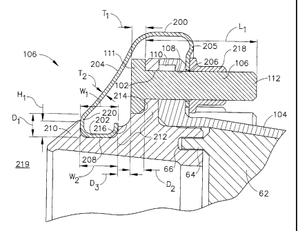
Figure 2 is an enlarged cross-sectional view of a portion of high pressure
compressor 14 including an exemplary shield assembly 100 coupled to a
compressor
stator body 58. Figure 3 is an enlarged cross-sectional view of shield
assembly 100.
In the exemplary embodiment, compressor 14 includes a plurality of stages 50
wherein each stage 50 includes a row of circumferentially-spaced rotor blades
52 and
a row of stator vane assemblies 56. Rotor blades 52 are typically supported by
rotor
disks 26, and are coupled to rotor shaft 32. Compressor 14 is surrounded by a
casing
62 that supports stator vane assemblies 56. Casing 62 forms a portion of a
compressor flow path extending through compressor 14. Casing 62 has rails 64
extending axially upstream and downstream of casing 62. To create a continuous
compressor flow path, rails 64 are coupled to slots 66 defined in adjacent
stator bodies
58, described in more detail below. Slots 66 are defined in at least one of an
upstream
surface and downstream surface of each stator body 58. Casing 62 is retained
in
position by coupling adjacent stator bodies 58 via flanges 76 and 104 and
fasteners
106, as described in more detail below.
Each stator vane assembly 56 includes a vane 74, a radial flange 76, and an
annular stator body 58. Each radial flange 76 extends radially outward from
stator
body 58. As is known in the art, vanes 74 are oriented relative to a flow path
through
compressor 14 to control air flow therethrough. In addition, at least some
vanes 74
are coupled to an inner shroud. Alternatively, compressor 14 may include a
plurality
of variable stator vanes utilized in lieu of fixed stator vanes 74.
Each stator body 58 includes a radial flange 76 and an opening 102 formed
therethrough. More specifically, in the exemplary embodiment, each opening 102
extends through each radial flange 76 of an upstream stator body 58. Stator
body 58
may also include a stator ring or flange 104 that extends substantially
axially from
-4-
CA 02611825 2007-11-22
208404
stator body 58. In the exemplary embodiment, stator ring or flange 104 extends
generally upstream from a downstream stator body 58. More specifically, in the
exemplary embodiment, each flange 104 of a downstream stator body 58 is
coupled to
each radial flange 76 of an adjacent upstream stator body 58 via a plurality
of
fasteners 106. In the exemplary embodiment, fastener 106 extends through
stator
body opening 102 and through an opening 108 in stator body flange 104 to
secure
flange 104 to an upstream stator body 58. In the exemplary embodiment,
fastener 106
is a D-Head bolt that is secured in position with a breakaway nut 110.
Fastener 106
has a fastener head 111 and a fastener body 112. Fastener head 111 has a
thickness of
T1. Fastener body 112 has a length of Li. In the exemplary embodiment,
fastener
body length L1 is greater that the length of the breakaway nut 110 to allow
flange 104
and a nut 218 to be coupled to fastener 106, as described in more detail
below.
In the exemplary embodiment, shield assembly 100 includes a shield 200
having an integrally-formed retaining portion 202, an aerodynamically
contoured
upstream surface 204, and a downstream surface 205. Upstream surface 204
extends
between retaining portion 202 and downstream surface 205. Downstream surface
205
includes a slot 206 extending therethrough and that is sized to receive
fastener 106
therethrough, as described in more detail below. Upstream surface 204 and
downstream surface 205 each have a thickness of T2. Retaining portion 202 has
a
width of W1, a depth of D1, and a thickness of T2. Shield 200 is arcuate with
a radius
R1 (shown in Fig. 5) where R1 is larger that the outer radius of casing 62
such that
shield 200 fits circumferentially about casing 62. In the exemplary
embodiment,
shield assembly includes a plurality of arcuate shields 200, each with a
radius of RI.
In the exemplary embodiment, stator body 58 is formed with a retaining
channel 208 that extends circumferentially around stator body 58 and is
defined
between an annular lip 210 and a stepped portion 212 of body 58. Retaining
channel
208 has a width W2. Lip 210 has a height of HI. Channel width W2 is larger
than
retaining portion width Wi such that retaining portion 202 may be inserted in
retaining channel 208. Stepped portion 212 extends outward from body 58 and,
in the
exemplary embodiment, is formed with a plurality of shoulders 214 and 216.
-5-
CA 02611825 2007-11-22
208404
Shoulder 214 is counter-bored to a depth D2, where D2 is substantially equal
to
fastener head thickness T1. Shoulder 216 is counter-bored to a depth of D3.
When
assembled, fastener head 111 is substantially flush with the outer edge of
shoulder
214. In the exemplary embodiment, when retaining portion 202 is positioned in
retaining channel 208, a portion of retaining portion 202 extends beyond
shoulder
216.
In the exemplary embodiment, shield assembly 100 is positioned just
downstream of an annular opening 219 in casing 62 and covers stator body
opening
102, fastener 106, and flange 104. Shield 200 is retained in position by
inserting
shield retaining portion 202 into retaining channel 208. Lip 210 contacts
shield 200
approximately at a point 220 where upstream surface 204 is coupled to
retaining
portion 202. In the exemplary embodiment, lip 210 and upstream surface 204
form a
continuous contour from stator body 58 at opening 219 to downstream surface
205.
Furthermore, in the exemplary embodiment, shield 200 is further secured by
coupling
shield 200 at slot 206 to flange 104 and breakaway nut 110 by utilizing shield
slot
206. Shield 200 is secured in position by coupling nut 218 to fastener body
112
downstream of breakaway nut 110, slot 206, and flange opening 108. When shield
assembly 100 is secured in position over stator body 58, shield assembly 100
creates
an aerodynamic surface between stator body 58 and the airflow.
Figure 4 is a perspective view of an exemplary shield assembly 100
including shield 200. Figure 5 is an exploded view of an exemplary shield
assembly
100 coupled to stator body 58. Figure 6 is a second enlarged cross-sectional
view of
an exemplary shield assembly 100 coupled to stator body 58 at an overlap
engagement 300. In the exemplary embodiment, shield assembly 100 includes a
first
overlap portion 222 and a second overlap portion 224 coupled to shield 200.
In the exemplary embodiment, first overlap portion 222 is recessed from
shield 200 by offset 01. More specifically, in the exemplary embodiment,
offset 01 is
substantially equal to shield thickness T2. First overlap portion 222 has an
upstream
surface 226 and a downstream surface 228. Upstream surface 226 and downstream
surface 228 each have a thickness of T3. In the exemplary embodiment,
thickness T3
-6-
CA 02611825 2007-11-22
208404
is substantially equal to shield thickness T2. Upstream surface 226 is
aerodynamically
contoured and has a contour substantially equal to that of upstream surface
204. An
aperture 230 having a radius R2 extends through downstream surface 228.
In the exemplary embodiment second overlap portion 224 is co-planar with
shield 200. Second overlap portion has an upstream surface 232, a downstream
surface 234, and a retaining portion 236. Upstream surface 232 and downstream
surface 234 each have a thickness T4. In the exemplary embodiment, thickness
T4 is
equal to thickness T2. Upstream surface 232 is configured to have
substantially the
same aerodynamic contour as upstream surface 204. Retaining portion 236 is
configured to have the same features and dimensions as retaining portion 202,
described above. Downstream surface 234 has an aperture 238 extending
therethrough. More specifically, in the exemplary embodiment, aperture 238 has
a
radius R3 that is equal to aperture radius R2.
In the exemplary embodiment, first overlap portion 222 is inserted between
second overlap portion 224 of an adjacent shield 200 and stator body 58. First
overlap portion 222 and second overlap portion 224 are configured to mate and
form
overlap engagement 300. Aperture 230 is configured to align with aperture 238
of
adjacent second overlap portion 224. Apertures 230 and 238 are further
configured to
align with a second opening 302 extending through stator body 58. Moreover, in
the
exemplary embodiment, flange 104 has a second opening 304 extending
therethrough.
Flange second opening 304 is sized to receive a retainer 306. More
specifically,
second opening 302 has a radius R4 where R4 is greater than R2 and/or R3 such
that
radius R4 is sized to receive retainer 306. Furthermore, in the exemplary
embodiment,
retainer 306 is a shank nut. Retainer 306 is positioned within stator body
second
opening 302 and flange second opening 304. Apertures 230 and 238 are
configured to
align with retainer 306 positioned in openings 302 and 304. Overlap portions
222 and
224 are secured to stator body by inserting a second fastener 308 through
apertures
230, 238 and into retainer 306. More specifically, in the exemplary
embodiment,
second fastener 308 is a traditional bolt. In the exemplary embodiment, when
apertures 230 and 238 are coupled to retainer 306, shield slot 206 is aligned
with
stator body opening 102.
-7-
CA 02611825 2007-11-22
208404
While engine 10 is in operation, shield assembly 100 facilitates reducing
aerodynamic bleed losses by providing an aerodynamic surface over which air
may
flow and experience a pressure recovery. Further, stator body 58, stator body
flange
104, and fastener 106 assembly is shielded from airflow of heated fluids. When
in
position, shield assembly 100 facilitates reducing the thermal expansion of
stator body
58, which thereby facilitates slowing the growth of the stator during
transient
conditions and reducing tip clearances. When first overlap portion 222 and
second
overlap portion 224 form overlap engagement 300, overlap engagement 300
facilitates
reducing leakage of air between shields 200 of shield assembly 100 and reduces
aerodynamic windage losses over the shield.
The above-described apparatus facilitates reducing losses in a compressor.
The shield assembly facilitates minimizing losses by creating an aerodynamic
surface
in the air flow path and aiding in pressure recovery. In the exemplary
embodiment, a
secondary air flow bled from the main compressor airflow flows over the
aerodynamic surface. The airflow across the stator body increases in
temperature of
the stator body because of friction between the fluid and the surface of the
stator body
(windage). By coupling the shield assembly upstream of the stator body, the
fluid has
an aerodynamic surface across which to flow, reducing friction between the
fluid and
the stator body. The reduction in windage maintains the secondary air flow at
a lower
temperature than in other known compressors. Furthermore, since the bleed air
flows
over the shield and does not directly impinge on the stator ring, the stator
ring is
shielded from the convection air flow. The overlapping shields create a low
convection cavity around the stator ring such that the shield facilitates
insulating the
stator ring from the air flow. Therefore, the shield assembly also facilitates
maintaining the desired stator thermal-displacement response to passively
control the
clearance between the rotating tip and the stationary inner surface of the
compressor
flow path. Because of the insulation effects of the shield assembly, the mass
of the
fastener at the stator body joints can be reduced while achieving the same
time
constant as a fastener with more mass.
Exemplary embodiments of a method and apparatus to facilitate reducing
losses in a compressor are described above in detail. The method and apparatus
is not
-8-
CA 02611825 2014-08-01
208404
limited to the specific embodiments described herein, but rather, components
of the
method and apparatus may be utilized independently and separately from other
components described herein. For example, the shield assembly may also be used
in
combination with other turbine engine components, and is not limited to
practice with
only stator body assemblies as described herein. Rather, the present invention
can be
implemented and utilized in connection with many other windage loss reduction
applications.
While there have been described herein what are considered to be preferred and
exemplary embodiments of the present invention, other modifications of these
embodiments falling within the scope of the invention described herein shall
be
apparent to those skilled in the art.
- 9 -