Note: Descriptions are shown in the official language in which they were submitted.
CA 02611980 2007-12-13
WO 2006/133551 PCT/CA2006/000968
VARIABLE EXHAUST CONTROL FOR SPRAY BOOTHS
FIELD OF THE INVENTION
The present invention relates to the field of spray booths exhausts
systems. More specifically, the present invention relates to an energy saving
exhaust system for a spray booth.
BACKGROUND OF THE INVENTION
Spray booths require an air circulation in order to maintain a safe
workplace for persons working in these booths. The amount of air circulated
through a workplace varies as a function of the flow rate required in the
design. In most cases, the latter is based on the speed of 100 feet per minute
required for the transport of particles when spraying. However, there are not
continuous spraying activities inside the spray booth. Indeed, there are many
periods of time during which no spraying occurs: personal breaks of painters,
time to prepare the equipment. All those periods of time only require a level
of
air exhaust permitting dilution ventilation. Such ventilation level is many
times
less than the one required for particles transportation. Maintaining a
constant
exhaust flow rate during these periods provides a significant waste of energy.
Canadian patent 1,134,129 describes a spray booth exhaust system
control. The use of the spray gun is detected by assuming that when the gun
is not on its stand or hooked on the wall, it must be used. Therefore, when
the
detection is made, a damper or register is activated such as to reduce the
exhaust air flow rate. The problem with this system is that, sometimes, the
spray gun is neither on its stand and nor being used. For example, it may well
be in the hands of the painter, but he is not actually painting with it, or
the
painter may have left the spray booth without having put back the spray gun
on its stand. This system still wastes energy during such time.
There is therefore a need for an improved energy saving exhaust
system for a spray booth.
1
CA 02611980 2007-12-13
PCT/CA2006/000968
13 April 2007 13-04-2007
SUMMARY OF THE INVENTION
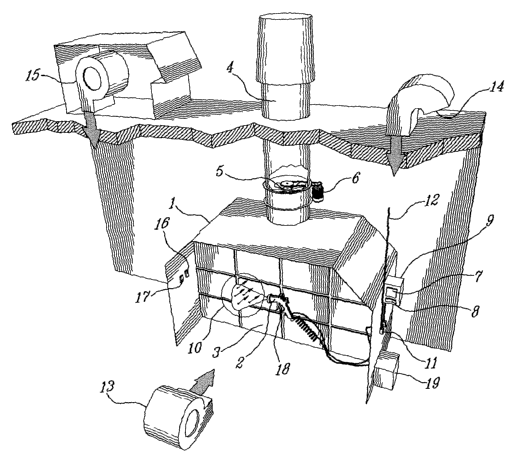
A chamber, a hall, a booth, or an area (1) used to confine the particles
emitted by at least a spraying device (2) is generally provided with a
filtering
member (3), which permits to reduce or eliminate evacuated particles in an
exhaust duct (4) by means of an exhaust fan (5). The exhaust fan is operated
by a motor (6), which is coupled to a variable speed controller (7). The
rotation speed of the fan is controlled by a control circuit (8) installed in
a
control cabinet (9) or is a member of the variable speed controller (7). The
exhaust level during the spraying is maintained at an adequate exhaust level
to assure particle transportation (10). When a spraying device is turned off,
the exhaust flow rate is reduced to a minimum by reducing the speed of the
exhaust fan (5). A detection device, such as a flow meter (11), a process
equipment trigger (18) or a pump operation detector (19), is generally
mounted on the spraying device (2) or on the compressed air inlet for the
spraying device (2), detects use of the spraying device (2) so as to indicate
to
the controller the necessity of increasing the exhaust at its normal activity
threshold.
Variation of the speed of the motor can be directly a function of the
detection of the spraying, or according to an exhaust model considering at
least the dimensions of the booth, the exhaust speed and estimated quantity
of aerosol matter or sprayed matter which is present in the air, as well as
the
acceptable quantity threshold.
It is therefore an object of the present invention to provide an exhaust
control system for a spray booth which overcomes the above drawbacks.
It is another object of the present invention to provide an exhaust
control system for a spray booth which saves energy.
It is another object of the present invention to provide an exhaust
control system for a spray booth which adjusts the exhaust as a function of a
spraying activity.
According to one aspect of the invention, there is provided an exhaust
control system for a spray booth having at least one fan motor. The exhaust
control system comprises a spraying activity detector and a speed control
circuit for an electrical motor. The speed control circuit is connected to the
fan
motor and is linked to the detector so as to adjust the speed of the fan motor
in a variable manner as a function of at least the spraying activity.
2
AMENDED SHEET
CA 02611980 2007-12-13
WO 2006/133551 PCT/CA2006/000968
Preferably, the spraying activity detector comprises a flow meter in a
compressed air feed of at least one spray gun. The flow meter may be
connected to, at its outlet, a plurality of spray guns. Advantageously, the
exhaust control system comprises a cabinet having a compressed air inlet, a
compressed air outlet, an electrical power supply input for the motor, and an
electrical power supply output for the motor. The cabinet contains the control
circuit and the flow meter. Preferably, the cabinet is further equipped with a
speed control signal output. The cabinet contains a logic unit of the control
circuit and the flow meter. The control circuit comprises a speed variator
unit
coupled to the motor receiving the speed control signal from the cabinet.
Alternatively, the spraying activity detector of the exhaust control
system comprises an opacity probe. The opacity probe is preferably located
within the spray booth in a location adequate to detect byproducts of spraying
activity. It is also possible for the spraying activity detector comprises to
use
an electrical contact activated by a trigger installed on a spray gun. Another
way of achieving the same result may also be accomplished by the spraying
activity detector being equipped with a motion detector in the spray booth to
detect the presence of an operator.
In any of these options, the speed of the motor is adjusted as a
function of the actual spraying activity. It is further possible to adjust the
speed
of the motor as a function of the actual spraying activity and time.
According to another aspect of the invention, there is provided a
method for controlling an exhaust system of the spray booth. The method
comprises the steps of detecting the spraying activity and, upon detection of
the spraying activity, increasing an air volume exhaust rate of the exhaust
system. Preferably, the method further comprises a step of increasing an air
volume rate of a make-up air supply. More preferably, the air volume exhaust
rate is increased to maximum values according to established standards.
The method is also provided with steps to detect the end of the
spraying activity and, upon detection of the end of the spraying activity,
reduce the air volume exhaust rate. Preferably, the air volume exhaust rate is
reduced after a period of time following the detection of the end of the
3
CA 02611980 2007-12-13
WO 2006/133551 PCT/CA2006/000968
spraying activity. More preferably, both the air volume exhaust rate and the
air
volume rate of the make-up air supply are reduced to minimal values.
Optionally, the method further comprises the steps of detecting a
failure of detecting the spraying activity and, upon detection of the failure
to
detect the spraying activity, increasing the air volume exhaust rate and the
air
volume of the make-up air supply to maximum values according to
established standards.
Applicants have found that by using this exhaust control system and
this methodology, energy savings are materialized.
BRIEF DESCRIPTION OF DRAWINGS
In the following description, which represents a preferred embodiment
of the invention, reference is made to the drawings included in the present
application wherein:
Figure 1 is a perspective view of a spray booth provided with an
exhaust system according to a preferred embodiment; and
Figure 2 is an electro-pneumatic diagram of an exhaust system
according to the preferred embodiment.
DETAILED DESCRIPTION OF THE INVENTION
A spraying process can include, without being limited to, the application
of paint, lacquer, or primer sealer, or the treatment of a surface. Such a
spraying process produces contaminants, solvents, dust or particles in
suspension, which are by-product of the spraying.
The present invention may be used in a process producing dust which
has to be evacuated, or in a process where the air acting as a carrier of dust
is exhausted or re-circulated in a building, an enclosure or a cabinet.
The definition of process equipment operation includes one or more
spraying processes and one or more processes producing dust.
In the case of spraying processes and processes producing dust
particles, the contaminants or dust particles must be evacuated in the work
area by an air movement across the work area. The air movement is usually
4
CA 02611980 2007-12-13
WO 2006/133551 PCT/CA2006/000968
produced by an exhaust fan (5). In certain cases, a fan (13) pushes
contaminants towards the exhaust enclosure ("push-pull" process).
The enclosure (1) is a chamber, a hall, a cabinet, or an enclosure
which is used to confine and direct solvents, dust particles and other
contaminants produced as a by-product of the spraying process and of the
process producing dust particles (10).
A filtration system (3) is generally installed in order to capture dust
particles (10) or particles before exhausting the air towards the exterior by
means of an exhaust conduit (4) or by re-circulating the process air where
this
is permitted or possible.
Exhausting or re-circulating air systems require energy in relation with
the propelling force of the fans (5) and (13).
In a building, air that is evacuated must be replaced by a natural
means such as an air intake (14) or by mechanical means such as an air
make-up (or fresh air inflow) (15). Such a replacement air must be conditioned
both to keep adequate processes temperatures and to provide comfort to the
occupants. Such conditioning of the air can be heating, humidifying,
dehumidifying, cooling or filtering. All of these processes for conditioning
air
use energy.
The objective of decreasing the exhausting of air is to both reduce the
energy used by the propelling force (6), (13) and (15) required to transport
or
displace air and to reduce the requirements in fresh air replacement which
has to be treated.
An objective of controlling the variation of the exhaust flow rate of the
spray exhaust processes and of the dust producing processes is to save
energy.
Control of the flow rate variation is initiated by the detection of the use
of spraying devices or of any other device producing contaminants that must
be evacuated. The control device (8) consists of an electronic circuit, which
receives an input signal corresponding to the detection of the use of the
process equipment, interpreting the signal as a requirement to exhaust at high
speed, and providing an output signal allowing varying the speed of the
exhaust fan, the re-circulation fan and/or the make-up air fan.
5
CA 02611980 2007-12-13
PCT/CA2006/000968
13 April 2007 13-04-2007
The detection signal of the use of the process equipment preferably
initiates from detecting a compressed air flow used in the process by
installing
a measuring device on the compressed air inlet (12).
In the case of the prototype, the detection of operation of the process
equipment was accomplished by using an in-line variable area flowmeter (11)
Omega model FLR-6720-I, provided with a 4-20 milliamps signal transmitter.
This flow meter (11) is installed on the compressed air line (12) supplying
the
spraying device (2).
The second recommended method of detection of process equipment
operation can be accomplished with the use of an in-line variable area flow
meter provided with a switch that is adjustable at a given flow rate. This
flow
meter (11) shall be installed on the compressed air line (12) supplying the
spraying device (2).
The third recommended method of detection of process equipment
operation can be accomplished with the use of a turbine flow meter provided
with an adjustable flow rate setpoint or with a signal transmitter. This flow
meter (11) shall be installed on the compressed air line (12) supplying the
spraying device.
In the three cases mentioned above, the flow meter (11) can be
installed at any location on the compressed air line (12) feeding the spraying
device (2). A cable transmits the signal to a control cabinet (9), which
contains
the command circuit (8).
The signal detecting the operation of the process equipment can also
be initiated by:
= An electrical contact activated by the process equipment trigger
(18).
= The detection of pump operation or operation of an apparatus
serving the process by a pump operation detector (19).
= Detecting the presence of an operator in the work area.
= A motion detector (16) located in the work area.
= A beam or a probe permitting to detect the presence of
contaminants. Such a probe may be, for example, an infrared
opacity probe (17). In this case, the probe is installed in a
6
AMENDED SHEET
CA 02611980 2007-12-13
WO 2006/133551 PCT/CA2006/000968
position adequate to detect dust particles (10), contaminants or
any spraying activity byproducts flowing in the direction of the
filtration system (3).
The control circuit can either be separated from the detection system or
be part of it.
Interpretation of the detection signal and the recommended action are
programmed in the command circuit (8). Recommended actions as function of
the input signals are described in the operation sequences.
In the case of the prototype, the speed variation of the exhaust fan (5),
the fan (13) and the air make-up (15) is controlled by means of a Toshiba
Series S-11 variable speed device. These speed controllers receive a 0-10
VDC signal from the command circuit (8).
The command circuit (8) can be separated from the variable speed
controller or can be an integral part of it.
The command circuit (8) can be an integral part of the detection and
variable speed controller systems.
The operation sequences comprise, but are not limited to, the following
elements:
= In a period where process equipment is not in operation,
exhaust and make-up air supply are at their minimal values.
= Upon detection of operation of the process equipment, the
exhaust and make-up air supply are increased to maximum
values according to established standards.
= Upon detection of the end of operation of the process
equipment, a timer allows the air volume exhaust rate to
continue at high speed for a given period of time and thereafter
reducing the speed.
= Upon detection of failure of a detection component, or of a lack
of information regarding the status, the system acts such as that
the exhaust and the make-up airflows are increased to
maximum values according to established standards.
7