Note: Descriptions are shown in the official language in which they were submitted.
CA 02611986 2007-12-13
WO 2006/133539 PCT/CA2006/000743
TOURNIQUET CUFF WITH IMPROVED PNEUMATIC PASSAGEWAY
FIELD OF THE INVENTION
This invention pertains to pneumatic tourniquet cuffs commonly used for
stopping
arterial blood flow into a portion of a surgical patient's limb to facilitate
the performance of a
surgical procedure, and for facilitating intravenous regional anesthesia.
BACKGROUND OF THE INVENTION
A typical surgical tourniquet system of the prior art includes a tourniquet
cuff for
encircling a patient's limb at a desired location and a tourniquet instrument
that includes
flexible instrument tubing for connecting to the tourniquet cuff. The
tourniquet cuff typically
includes an inflatable portion, and the inflatable portion of the cuff is
typically connected
through a cuff port having a port connector to the flexible instrument tubing
of the tourniquet
instrument, thereby establishing a pneumatic passageway from the tourniquet
instrument
through the instrument tubing and the cuff port into the inflatable portion of
the cuff. In some
prior-art systems, the tourniquet instrument includes a pressure transducer to
sense the pressure
of gas at the instrument end of the pneumatic passageway and to enable the
sensed pressure to
be displayed for surgical staff. Some prior-art tourniquet instruments include
a pressure
regulator to increase and decrease the pressure of gas in the pneumatic
passageway, and to
maintain the pressure in the inflatable portion of the cuff at a pressure
above a minimum
pressure required to stop arterial blood flow past the cuff during a time
period suitably long for
the performance of a surgical procedure. Many types of pneumatic surgical
tourniquet
systems, including tourniquet cuffs and tourniquet instruments, have been
described in the prior
art, such as those described by McEwen in U.S. Patent No. 4,469,099, No.
4,479,494, No.
5,439,477 and by McEwen and Jameson in U.S. Pat. No. 5,556,415 and No.
5,855,589.
Some tourniquet cuffs of the prior art have only a single port for connection
to the
tourniquet instrument and thus establish only a single pneumatic passageway
between a
tourniquet instrument and the inflatable portion of such cuffs. The pressure
in the inflatable
portion of such single-port tourniquet cuffs must be sensed indirectly from
the tourniquet
CA 02611986 2007-12-13
WO 2006/133539 PCT/CA2006/000743
2
instrument, through the same pneumatic passageway that is used by the
tourniquet instrument
to increase, decrease and regulate cuff pressure during surgery. The flow
resistance of the
pneumatic passageway affects the accuracy and speed of regulation of pressure
within the
inflatable portion of such single-port tourniquet cuffs as well as the
accuracy of the indirectly
sensed tourniquet cuff pressure.
Other tourniquet cuffs of the prior art have dual ports to establish two
separate
pneumatic passageways between the tourniquet instrument and the inflatable
portion of the
cuff, to achieve increased safety and performance by enabling the tourniquet
instrument to
provide surgical staff with a more accurate indication of cuff pressure and by
enabling the
tourniquet instrument to increase the speed and accuracy of cuff pressure
regulation.
Representative dual-port tourniquet cuffs of the prior are described in U.S.
Pats. No. 4,635,635,
No. 5,454,831, No. 5,439, 477, No. 5,741,295 and No. 5,649,954. In one dual-
port tourniquet
system of the prior art, described in U.S. Pat. No. 4,469,099, the pneumatic
pressure regulation
elements within the tourniquet instrument communicate with the inflatable
portion of the
tourniquet cuff through one pneumatic passageway of the tourniquet cuff, and a
pressure sensor
within the tourniquet instrument communicates pneumatically with the
inflatable portion of the
cuff through a separate pneumatic passageway of the cuff.
With both single and dual-port tourniquet systems, the speed and accuracy of
pressure regulation and indication are improved if flow restrictions in the
pneumatic
passageway are minimized. Typical port connectors of the prior art have a male
barbed
connection portion which fits inside the pneumatic passageway of the port,
creating a region of
reduced pneumatic flow area and increasing flow resistance between the cuff
and the tourniquet
instrument.
One hazard associated with all pneumatic tourniquet cuffs of the prior art is
the
obstruction of the pneumatic passageway within the cuff. For example, in a
single-port
tourniquet cuff, a complete obstruction within the pneumatic passageway may
allow the actual
pressure in the inflatable portion of the cuff to decrease substantially below
the desired
tourniquet pressure to a level where the cuff may be completely depressurized,
or to increase
substantially above the desired tourniquet pressure, without any indication to
the surgical staff.
CA 02611986 2007-12-13
WO 2006/133539 PCT/CA2006/000743
3
In effect, the monitoring and regulation of cuff pressure by a prior-art
tourniquet instrument
stops at the location of the obstruction. As another example, a complete
obstruction within a
region of the inflatable portion of the cuff may isolate all or part of the
inflatable portion and
thus may prevent the pressure throughout the entire inflatable portion of the
cuff from being
sensed and regulated near the desired pressure by the tourniquet instrument.
Any isolated
region may be hazardous, either by permitting arterial blood to flow into the
limb past a region
of lower cuff pressure or by requiring surgical staff to set the tourniquet
instrument to an
unnecessarily high pressure to stop blood flow past the cuff. Also, any
complete obstruction of
the pneumatic passageway within a tourniquet cuff of the prior art may render
ineffective any
audio-visual safety alarms of a connected prior-art tourniquet instrument
intended to warn of
hazardous over-pressurization or under-pressurization of the cuff, such as the
safety alarms
described by McEwen in U.S. Pat. No. 4,469,099.
Another hazard associated with tourniquet cuffs of the prior art is partial
obstruction
of the pneumatic passageway. A partial obstruction of the pneumatic passageway
at the port
connector, or elsewhere within the port or inflatable portion of a prior-art
cuff may increase the
pneumatic flow resistance at the partial obstruction, and thus may affect the
ability of a
connected tourniquet instrument to rapidly and accurately regulate pressure
past the partial
obstruction and throughout the inflatable portion of the tourniquet cuff.
Increased flow
resistance from a partial obstruction may also reduce the ability of a
connected tourniquet
instrument to accurately and rapidly indicate changes of the pressure in the
tourniquet cuff to
surgical staff. Further, a partial obstruction of the pneumatic passageway
within a region of
the inflatable portion of the cuff may affect the ability of the tourniquet
instrument to uniformly
regulate pressure throughout the entire inflatable portion of the cuff.
In addition to the hazards of complete and partial obstructions that may
affect the
integrity of the pneumatic passageway, another hazard associated with prior-
art cuffs is the
interruption of the passageway due to unanticipated detachment of the port
connector from the
tourniquet instrument, or detachment of the port connector from the port, thus
separating the
inflatable portion of the tourniquet cuff from the tourniquet instrument. A
related hazard is a
leak at the port connector that is sufficiently large to prevent a connected
tourniquet instrument
CA 02611986 2007-12-13
WO 2006/133539 PCT/CA2006/000743
4
from maintaining cuff pressure near the desired pressure. Such a large leak
may result, for
example, from deterioration or deformation of the connector of a single-use
disposable
tourniquet cuff as a result of reprocessing and reuse of the disposable
tourniquet cuff in
multiple surgical procedures in a manner neither intended nor anticipated by
the manufacturer.
Many disposable tourniquet cuffs of the prior art are designed to be used in
only one
single surgical procedure and then discarded. Many such disposable tourniquet
cuffs are
sterilized at time of manufacture and supplied to users as sterile products,
because such cuffs
are typically intended to be suitable for use within sterile surgical fields.
As a result, the design
characteristics of such prior-art cuffs are intended to allow them to be
applied and used safely
and reliably within a sterile surgical field during one surgical procedure,
and to be discarded
cost-effectively after that procedure. For example, some disposable tourniquet
cuffs of the
prior art have a port that includes a very flexible thermoplastic tubing
portion having a length
sufficient to allow a user to easily bend the port away from the surgical site
and position the
port connector beyond the sterile surgical field. Although such long and
flexible port tubing
facilitates connection of the port to non-sterile instrument tubing away from
the sterile surgical
field, it may also increase the possibility of partial or complete obstruction
of the pneumatic
passageway within the port, for example by accidental kinking, bending, or
pinching of the
tubing. The various materials and components from which such prior-art
disposable tourniquet
cuffs are assembled are chosen to be sufficiently inexpensive to allow the
cuff to be
economically discarded after a single use, and also to be capable of
sterilization by exposure to
a specific sterilizing agent within a specific sterilizing process determined
by the manufacturer,
with no significant deterioration or change of properties that would impair
the safety or
performance of the cuffs after such sterilization.
Efforts have been made to reprocess and reuse tourniquet cuffs of the prior
art that
were originally supplied by their manufacturers as sterile, single-use
products. Reprocessing
efforts typically involve saving rather than discarding a disposable
tourniquet cuff after
surgery, visually examining the cuff to identify any obvious deterioration
that might suggest
reprocessing is not appropriate, attempting to remove any blood and other
surgical debris by
washing the cuffs with water combined with any of a variety of detergents or
other cleaning
CA 02611986 2007-12-13
WO 2006/133539 PCT/CA2006/000743
liquids, in some cases conducting some functional tests of the cuff, re-
packaging the cuff and
then sterilizing the re-packaged cuff by exposing it to a sterilization agent
within a sterilization
process that may be different from that determined by the original
manufacturer to be safe and
effective. Reprocessing of disposable tourniquet cuffs may be carried out
within hospitals or
surgery centers or by third-party reprocessors, and the quality and methods of
reprocessing are
highly variable.
Reprocessing, cleaning and re-sterilizing of disposable tourniquet cuffs may
result in
hazards for the surgical patients on whom such cuffs are subsequently used.
The hazard arises
from the use of any of a variety of chemical or physical agents that are
attendant with the
reprocessing, cleaning or re-sterilizing processes. For example, exposure of a
cuff to liquids
during cleaning may allow the liquids to enter the pneumatic passageway of the
cuff, where
they may remain to partially or complete obstruct the pneumatic passageway of
the cuff within
the port or inflatable portion. Water remaining within the pneumatic
passageway after
cleaning may subsequently react chemically with ethylene oxide, a sterilizing
agent commonly
used in reprocessing, to form ethylene glycol, a sticky substance that may
completely or
partially block the pneumatic passageway. Exposure of prior-art cuffs to
sterilizing agents
different than the sterilizing agent employed at the time of manufacture may
produce a change
and deterioration in the properties of some cuff materials and components, for
example due to a
chemical reaction or exposure to radiation. Exposure of a prior-art cuff
containing flexible
thermoplastic materials to an elevated temperature during cleaning or
sterilization by known
prior-art processes may soften thermoplastic materials and components,
increasing the
likelihood of hazardous deformation of some components. For example, an
elevated
temperature during reprocessing may result in substantial deformation of the
thermoplastic
stiffener included in some prior-art cuffs, thus impairing the application of
pressure by such a
cuff to an underlying limb upon subsequent use in surgery. Also, an elevated
temperature
during reprocessing may deform the thermoplastic connectors of some prior-art
cuffs, or may
weaken the retention force of typical thermoplastic barb-type port connectors,
so that such
connectors cannot establish or reliably maintain a gas-tight passageway
between the tourniquet
cuff and tourniquet instrument upon reuse. An elevated temperature associated
with cleaning or
CA 02611986 2013-12-31
6
re-sterilization increases the likelihood that the pneumatic passageway within
the cuff may
become partially or completely obstructed, as described above, as a result of
such
reprocessing. Repeated cleaning, re-sterilization and reuse of a disposable
tourniquet cuff in
multiple surgical procedures may progressively increase the hazard for the
surgical patients
on whom the cuff is used.
There is a need for a tourniquet cuff that has minimal flow restrictions
within its
pneumatic passageway under normal operating conditions, that has a
substantially reduced
likelihood of partial or complete obstructions or interruptions of the
pneumatic passageway
under foreseeable operating conditions, that can indicate exposure of the cuff
to one or more
external agents that are capable of affecting the integrity of the pneumatic
passageway before
use, and that can be manufactured economically. The present invention
addresses this need.
Accordingly, there is provided a tourniquet cuff having a pneumatic
passageway,
comprising: a first layer of flexible thermoplastic material having a first
layer sealing surface,
a second layer of flexible thermoplastic material having a second layer
sealing surface facing
the first layer sealing surface, a perimeter seal establishing a gas-tight
seal between the first
layer sealing surface and the second layer sealing surface around a
predetermined perimeter to
form an inflatable bladder within the perimeter seal, wherein the perimeter
seal comprises a
continuous bead of thermoplastic material along the perimeter of the
inflatable bladder
formed from squeezed, melted portions of the first and second layers that have
solidified to
form the bead to protrude from the seal into the inflatable bladder and having
a bead thickness
greater than a predetermined bead thickness for separating the first sealing
surface from the
second sealing surface, thereby establishing a bladder pneumatic passageway
near the bead,
and a port having a bladder sealing flange sealed to the first layer sealing
surface around the
flange, the sealing flange passing through the first layer so that a bottom
surface of the sealing
flange is inside the inflatable bladder to establish a port passageway from a
distal port end
outside the first layer through the port and into the bladder near the edge of
the bladder
sealing flange along a channel that is formed in the bottom surface of the
bladder sealing
flange, the channel extending from the outer perimeter of the flange to the
port passageway.
CA 02611986 2013-12-31
. .
6a
There is also provided a method of making a tourniquet cuff having a pneumatic
passageway, comprising: providing a first layer of flexible thermoplastic
material having a
first layer sealing surface, providing a second layer of flexible
thermoplastic material having a
second layer sealing surface facing the first layer sealing surface, sealing
together the first and
second layers at a perimeter seal, thereby establishing a gas-tight seal
between the first layer
sealing surface and the second layer sealing surface around a predetermined
perimeter to form
an inflatable bladder within the perimeter seal, wherein the perimeter seal
includes a bead of
thermoplastic material formed from squeezed, melted portions of the first and
second layers
that have solidified to form the bead to protrude from the seal into the
inflatable bladder and
having a bead thickness greater than a predetermined bead thickness for
separating the first
sealing surface from the second sealing surface, thereby establishing a
bladder pneumatic
passageway near the bead; and providing a port having a bladder sealing flange
sealed to the
first layer sealing surface around the flange, the port passing through the
first layer so that a
surface of the flange is inside the inflatable bladder to establish a port
passageway from a
distal port end outside the first layer through the port and into the bladder
near the edge of the
bladder sealing flange along a channel that is formed in the bottom surface of
the bladder
sealing flange that is inside the inflatable bladder.
There is further provided a method of inflating with gas an elongated,
inflatable, two-
layer bladder of a tourniquet cuff, wherein the cuff is secured around the
limb of a patient
with the layers thereof pressed together, comprising the steps of: sealing
together side edges
of top, middle, and bottom layers of material to form a gas-inflatable bladder
between the
bottom and middle layers; stiffening the cuff with an elongated stiffener
member that is
enclosed within an enclosure formed between the middle and top layers, the
stiffener being
movable within the enclosure and arranged to compress the portion of the
bladder underlying
the stiffener inwardly toward the limb; preventing the middle and bottom
layers of the bladder
from contacting each other at a location adjacent to a sealed edge of the
bladder, thereby to
provide a continuous pneumatic passageway adjacent to the sealed edge for
distributing
inflating gas along the length of the bladder; limiting the width of the
stiffener member to be
less than the distance between the sealed side edges of the cuff thereby to
prevent the stiffener
from overlying and thereby compressing the continuous pneumatic passageway;
providing a
CA 02611986 2013-12-31
6b
port opening into the sealed bladder; separating the middle and bottom layers
that form the
bladder adjacent the port opening with a flange member that together with the
bottom layer
defines a channeled passageway extending away from the port opening for
delivering gas
through the channeled passageway, beyond the flange member and into the
inflatable bladder;
and receiving pressurized gas from the port opening and directing the
pressurized gas through
the channeled passageway and toward the continuous pneumatic passageway
thereby to
separate the pressed-together layers of the bladder by an amount sufficient to
pneumatically
connect the channeled passageway and the continuous pneumatic passageway and
thereby
distribute inflating gas along the length of the bladder for inflating the
entire bladder to the
pressure of the pressurized gas.
There is also provided a method of making an elongated tourniquet cuff having
a
bladder that may be secured around the limb of a patient when deflated,
comprising the steps
of: sealing together side edges of top, middle and bottom layers to form a gas-
inflatable
bladder between the bottom and middle layers; preventing the two layers of the
bladder from
contacting each other at a location adjacent to a sealed edge of the bladder
thereby to provide
a continuous pneumatic passageway adjacent to the sealed edge for distributing
inflating gas
along the length of the bladder, including forming and sizing a bead to
separate the bottom
and middle layers adjacent to the sealed edge by at least a selected amount
that is greater than
the separation between the middle and top layers adjacent to the sealed edge,
wherein the
bead is disposed completely between the bottom and middle layer; providing a
port opening
into the sealed bladder; separating the bottom and middle layers adjacent to
the port opening
with a flange member that together with the bottom layer defines a channeled
passageway
extending away from the port opening for delivering pressurized gas from the
port opening
through the channeled passageway, beyond the flange member, and into the
inflatable
bladder.
There is also provided a method of making an elongated tourniquet cuff having
a
bladder that may be secured around the limb of a patient when deflated,
comprising the steps
of: sealing together side edges of top, middle and bottom layers to form a gas-
inflatable
bladder between the bottom and middle layers; preventing the two layers of the
bladder from
contacting each other at a location adjacent to a sealed edge of the bladder
thereby to provide
CA 02611986 2013-12-31
=
6c
a continuous pneumatic passageway adjacent to the sealed edge for distributing
inflating gas
along the length of the bladder, including forming and sizing the sealed-
together edges of the
bottom and middle layers to separate the bottom and middle layers adjacent to
the sealed edge
by at least a selected amount that is greater than the separation between the
middle and top
layers adjacent to the sealed edge; providing a port opening into the sealed
bladder; separating
the bottom and middle layers adjacent to the port opening with a flange member
that together
with the bottom layer defines a channeled passageway extending away from the
port opening
for delivering pressurized gas from the port opening through the channeled
passageway,
beyond the flange member, and into the inflatable bladder.
BRIEF DESCRIPTION OF THE DRAWINGS
FIG. 1 is a pictorial representation of the preferred embodiment in a surgical
application.
FIG. 2 shows the cuff portion of the preferred embodiment.
FIG. 3a is a section taken from Fig. 2, with the uninflated cuff applied to
the patient's
limb as shown in Fig. 1.
FIG. 3b is a section taken from Fig. 2, with the cuff applied to the patient's
limb and
inflated.
FIG. 4 is a view looking on the bottom surface of the bladder sealing flange.
FIG. 5 is a section taken from Fig. 4.
FIG. 6a is a section taken from Fig. 2, showing the preferred embodiment.
FIG. 6b is a section taken from Fig. 2, showing an alternative cross-sectional
profile.
FIG. 7a is a detail view of the areas indicated in Fig. 3a and Fig. 3b,
showing the
preferred embodiment.
FIG. 7b is a detail view of the areas indicated in Fig. 3a and Fig. 3b,
showing an
alternate embodiment.
CA 02611986 2007-12-13
WO 2006/133539 PCT/CA2006/000743
7
DETAILED DESCRIPTION OF THE PREFERRED EMBODIMENT
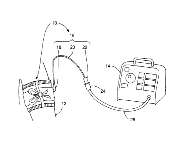
FIG. 1 is a pictorial representation of the preferred embodiment in a surgical
application, showing the tourniquet cuff 10 applied to patient limb 12 and
pneumatically
connectable to tourniquet instrument 14. Cuff 10 includes cuff port 16, which
comprises
bladder sealing flange 18, port tubing 20, and port connector 22. In the
preferred embodiment
shown, cuff 10 is a single port cuff, where cuff port 16 provides a single
pneumatic passageway
to the inflatable portion of cuff 10. Those skilled in the art will appreciate
that the features
described in the preferred embodiment may also be applied to tourniquet cuffs
having more
than one port, such as those described by U.S. Patent No. 4,469,099, No.
4,479,494, and No.
5,254,087. Cuff port 16 is pneumatically connected to tourniquet instrument 14
via instrument
connector 24 and instrument tubing 26. In the preferred embodiment cuff port
16 is of
sufficient length to allow pneumatic connection between cuff 10 and instrument
14 to be made
outside a sterile surgical field. Port connector 22 is a locking connector
(based on the
connector of the tourniquet cuff described by McEwen in U.S. Pat. No.
5,649,954 and similar
in some design aspects to connector DSM2202, Colder Products Company, St.
Paul, MN)
which allows cuff port 16 to form a releasable pneumatic connection with
instrument connector
24.
As described below, cuff 10 is constructed of materials that are appropriate
for a
single-use sterile disposable tourniquet cuff. To permit cuff 10 to be used in
a sterile surgical
field, cuff 10 is sterilized at time of manufacture by exposure to a
sterilizing agent within a
sterilizing process determined to be safe and effective. To prevent
deterioration of the cuff, and
to maintain the integrity of the pneumatic passageways within cuff 10, a
sterilization agent and
process that will not harm the materials or components of cuff 10 is selected
by the
manufacturer. In the preferred embodiment cuff 10 is sterilized by exposure to
gamma
radiation or electron beam radiation.
The cost of materials is an important consideration in the manufacture of
tourniquet
cuffs intended for a single use and then disposal. To minimize the cost of
materials and
assembly of cuff 10, materials are selected which are not intended to
withstand exposure to
subsequent sterilization and cleaning processes. The subsequent sterilization
or cleaning of
CA 02611986 2007-12-13
WO 2006/133539 PCT/CA2006/000743
8
cuff 10 by agents and processes commonly used in health care facilities, such
as ethylene oxide
gas sterilization, hydrogen peroxide gas sterilization, high temperature and
pressure steam
sterilization, sterilization by other chemical agents, and pasteurization, are
all capable of
adversely affecting the integrity of the pneumatic passageways of cuff 10. As
described further
below, cuff 10 includes one or more components that act as visual indicators
to warn a user that
cuff 10 has been subjected to a subsequent sterilization or cleaning process
capable of
adversely affecting cuff 10 and that cuff 10 may no longer be safe to use.
FIG. 2 shows the cuff 10 of the preferred embodiment, which is similar in
design and
construction to the cuffs described by McEwen in U.S. Patent No. 5,741,295,
No. 5,649,954,
No. 5,484,831 and by Robinette-Lehman in U.S. Patent No, 4,635,635. In the
preferred
embodiment shown, cuff 10 is rectangular with a length sufficient to encircle
an adult arm as
shown in Fig. 1. Those skilled in the art will appreciate that the features
described in the
preferred embodiment may also be incorporated in cuffs of various sizes and
shapes, such as
those described by McEwen in U.S. Patent No. 5,649,954. In addition to cuff
port 16, cuff 10
comprises tie ribbon 28, loop material 30, edge trim 32, sewn joint 34, and
hook material 36.
In use, cuff 10 is wrapped snugly around the limb 12 (see Fig. 1) and secured
circumferentially
around the limb when the user engages hook material 36 to loop material 30.
Tie ribbon 28 is a
soft fabric ribbon material (Grosgrain 5/8" wide, Dynatex Textiles Inc.,
Toronto, Ontario,
Canada) and allows the user to pull cuff 10 snug around the limb. When cuff 10
is in position
and secured circumferentially around the limb, the user ties tie ribbon 28 as
shown in Fig. 1 to
help prevent the cuff from sliding proximally or distally on the limb when
inflated. Edge trim
32 is made of similar material to tie ribbon 28 and helps prevent chafing of
the patient's limb
by the edges of cuff 10.
FIG. 3a is a section taken from Fig. 2, however with cuff 10 applied to the
limb 12
(as shown in Fig. 1) and cuff 10 uninflated. Top layer 38 and bottom layer 40
are made of
woven nylon cloth coated with thermoplastic material (for example, 200 Denier
nylon cloth
coated in thermoplastic polyurethane 0.006" thick) on the surfaces that face
middle layer 42.
Middle layer 42 is made of thermoplastic sheet material (for example, 0.020"
thick
polyurethane). Stiffener 44 is made of plastic sheet cut to a rectangular
shape fitting within the
CA 02611986 2007-12-13
WO 2006/133539 PCT/CA2006/000743
9
perimeter of cuff 10. The stiffener 44 has greater stiffness than layers 38,
40, and 42 but is
flexible enough to be wrapped around the limb (for example 0.020" thick
polyethylene sheet).
Top layer 38, middle layer 42, and bottom layer 40 are joined around a
continuous perimeter
within the perimeter of cuff 10 at bladder seal 46, thereby forming inflatable
bladder 48
between middle layer 42 and bottom layer 40 and enclosing thermoplastic
stiffener 44 between
top layer 38 and middle layer 42. Bladder 48 therefore has a width at the port
location as
shown in Fig. 3a, a typical value being 3.5 inches, and a length extending
along the length of
the cuff (see Fig. 2) and sufficient to encircle the limb. When secured
circumferentially around
the limb as shown in Fig. 1, stiffener 44 helps direct the expansion of
inflatable bladder 48
radially inwards towards the limb upon inflation of the cuff. The stiffener
thus provides
uniformly distributed pressure onto limb 12.
Bladder seal 46 is formed by a heat and pressure joining process, typically
radio-
frequency welding using a selected sealing die. The heat of the joining
process is selected to
temporarily melt a portion of the thermoplastic materials in layers 38, 40,
and 42, causing them
to fuse together in the area of bladder seal 46. The pressure of the joining
process in
combination with the shape of the sealing die is selected to squeeze a
predetermined portion of
the melted thermoplastic materials in layers 38, 40, and 42 out of the area of
bladder seal 46,
forming a continuous bead 50 along the perimeter of inflatable bladder 48.
When the joining
process is complete, bead 50 solidifies back to the original rigidity of the
thermoplastic
materials in layers 38, 40, and 42 and has thickness 51 (shown in Fig. 3b only
for clarity).
Thickness 51 is proportional to the selected amount of thermoplastic material
squeezed out
during the formation of bladder seal 46, and is selected to be large enough to
form and maintain
bladder pneumatic passageway 52 when bottom layer 40 is compressed against
middle layer 42
during certain conditions of use, which are described in more detail below.
Cuff port 16 of cuff 10 comprises port connector 22, port tubing 20, and
bladder
sealing flange 18, which are permanently joined together with pneumatically
sealed joints to
form port tubing pneumatic passageway 54 and port connector pneumatic
passageway 55 (see
Fig. 7a) which form a continuous pneumatic passageway extending from distal
port end 53 to
inflatable bladder 48. Bladder sealing flange 18 has flange top surface 56
which is permanently
CA 02611986 2007-12-13
WO 2006/133539 PCT/CA2006/000743
joined to middle layer 42 by a heat sealing process similar to that used to
form bladder seal 46
(as described above). Bladder sealing flange 18 also has bottom surface 58.
Port tubing 20 has
a length between bladder end 59 and port connector 22, which is at minimum
greater than the
bladder width at the port location, and preferably 30 inches, which is
sufficient to extend
outside the sterile surgical field. Bladder sealing flange 18 forms a portion
of pneumatic
passageway 54 extending from port tubing bladder end 59 and formed to enter
inflatable
bladder 48 in a direction normal to top surface 56 and bottom surface 58 of
bladder sealing
flange 18, and thereby normal to the area of middle layer 42 around bladder
sealing flange 18.
FIG. 3b is a section taken from Fig. 2, however with cuff 10 applied to the
limb 12
(as shown in Fig. 1) and cuff 10 inflated. Inflatable bladder 48 is shown
expanded radially
inwards towards the limb.
FIG. 4 is a view looking on bottom surface 58 of bladder sealing flange 18.
Bladder
sealing flange 18 is made of thermoplastic polyurethane by injection molding
(in a similar
manner to existing sealing flanges such as 167ACU-BK, Halkey Roberts Corp.,
St. Petersburg,
FL which are currently used in tourniquet cuffs). A plurality of channels 60
are formed in
surface 58 extending from the outer perimeter of flange 18 to port pneumatic
passageway 54.
FIG. 5 is a section taken from Fig. 4, showing a typical channel 60 formed in
the area
between flange bottom surface 58 and flange top surface 56. Because bladder
sealing flange 18
must be heat sealed to middle layer 42, channels 60 may be formed in to
surface 58 by
correspondingly shaped ridges on the sealing die and therefore are formed
during the heat
sealing process of bladder sealing flange 18 to middle layer 42 with no
additional per item cost
compared to the typical prior-art tourniquet cuffs.
Referring to FIGS. 1, 3a, 4, and 5, when port connector 22 is connected to
instrument
14, a pneumatic passageway is established from instrument 14 through port
pneumatic
passageway 54 (formed by the openings in port connector 22, port tubing 20,
and bladder
sealing flange 18), channels 60 in bladder sealing flange bottom surface 58
into inflatable
bladder 48. Bead 50 acts to hold open the bladder 48 near the bladder seal 46
thereby
establishing a bladder pneumatic passageway 52 around the perimeter of
inflatable bladder 48,
allowing pneumatic communication throughout the bladder.
CA 02611986 2007-12-13
WO 2006/133539 PCT/CA2006/000743
11
If bladder sealing flange 18 is compressed against limb 12 (for example if the
flange
area of the cuff is lying between the limb and the operating room table or
bolster on which the
limb is resting, or cuff 10 is applied to limb 12 too tightly), bottom layer
40 may be pressed
against flange bottom surface 58 as shown in Fig. 3a. On bladder sealing
flanges typically used
in tourniquet cuffs of the prior art (for example see 167ACU-BK, Halkey
Roberts Corp., St.
Petersburg, FL), surface 58 is flat and smooth. Using prior-art flanges in the
condition shown
in Fig. 3a, pneumatic communication between inflatable bladder 48 and port
pneumatic
passageway 54 is closed off or restricted. In the current invention, however,
channels 60 form
a plurality of pneumatic passageways between inflatable bladder 48 and port
pneumatic
passageway 54 in the area between flange bottom surface 58 and flange top
surface 56, which
remain open when bottom layer 40 is compressed against flange bottom surface
58.
Furthermore, if any area of the cuff containing inflatable bladder 48 is
compressed
against the limb, bottom layer 40 may be pressed against middle layer 42 in
some areas (as
shown in Fig. 3a) which may restrict or close pneumatic communication between
different
regions of inflatable bladder 48. Bead 50 separates middle layer 42 and bottom
layer 40,
thereby establishing bladder pneumatic passageway 52 extending around the
entire perimeter of
inflatable bladder 48 as noted above. The size of bead 50 is selected such
that bladder
pneumatic passageway 52 is maintained under the compression forces between
bottom layer 40
and middle layer 42 expected in surgical use, thereby maintaining pneumatic
communication
among all regions of bladder 48.
In addition to the conditions described above which may occur during the
normal use
of cuff 10, exposure of cuff 10 to an elevated temperature or pressure, or
exposure of cuff 10 to
certain chemicals, or a combination of these conditions may occur during
storage, shipping, or
subsequent cleaning and sterilization processes and may cause bottom layer 40
to adhere to
flange bottom surface 58 or areas of middle layer 42 by softening the
thermoplastic materials.
If the materials adhere, pneumatic passageways will nonetheless be maintained
by bead 50 and
channels 60.
FIG. 6a is a section taken from Fig. 2, showing the cross-sectional profile of
port
tubing 20 of cuff port 16, extending from bladder end 59 (see Figs. 3a and 3b)
to port tubing
CA 02611986 2007-12-13
WO 2006/133539 PCT/CA2006/000743
12
end 61 (see Fig. 7a). Port tubing 20 is formed by an extrusion process and is
made of a blend
of thermoplastic polyurethane and sterilization indicator formulated to change
color when
exposed to certain agents that, as noted above, may have a deleterious effect
on the integrity of
the pneumatic passageway. In this embodiment, the sterilization indicator does
not react to
change color during the initial sterilization of cuff 10 by gamma or electron
beam radiation at
time of manufacture. In the preferred embodiment, the thermoplastic material
is formulated to
undergo a distinct and permanent color change upon exposure to predetermined
minimum
levels of one or more selected sterilizing agents different than the agent
employed at time of
manufacture and typical of those commonly used within health care facilities
and by
reprocessors. Ethylene oxide gas is one such secondary sterilizing agent that
may be used in a
reprocessing sterilization process. Other agents are hydrogen peroxide gas,
high temperature
steam, and other chemical sterilizing agents. This color change occurs over
the length of port
tubing 20 and is visually perceptible by the user to indicate that cuff 10 has
undergone a
subsequent sterilization capable of affecting the pneumatic communication
described above and
shown in Fig. 3a. To enhance the appearance of the color change that takes
place within port
tubing 20 upon exposure to a subsequent sterilizing process, a portion of port
tubing 20 may be
marked with a substance that does not change color upon exposure to the
sterilization process.
For example, port tubing 20 may be formed from a thermoplastic material that
normally has a
clear color and changes to a brown color upon exposure to the ethylene oxide
sterilization
process. Port tubing 20 may also be marked with a white stripe which runs the
length of port
tubing 20. When port tubing 20 is exposed to the sterilization process the
printed white stripe
provides visual contrast to the underlying, brown colored tubing.
In the preferred embodiment the secondary sterilization indicator described
above is
formulated from a color-forming compound pre-selected to react with a
predetermined
minimum level of ethylene oxide in a secondary sterilization process. Color-
forming
compounds such as 4-(hydrazinocarbonyl) pyridine, 4-nitrobenzylpyridine, or
other pyridines
that react with ethylene oxide may be used alone or in combination to produce
a non-reversible
color change reaction upon exposure to ethylene oxide gas. The color-forming
compound may
also include catalysts that further promote the color change reaction. To
increase utility, the
CA 02611986 2007-12-13
WO 2006/133539 PCT/CA2006/000743
13
secondary sterilization indicator of the preferred embodiment may be mixed
with additional
color-forming compounds known in the art that react to change color in the
presence of
hydrogen peroxide gas or high temperature steam. The sterilization indicator
may also include
other non-reactive pigments pre-selected to enhance the visibility of the
color-forming
compound in its reacted state, thereby making a color change more visually
perceptible by a
user.
To further indicate to a user that cuff 10 has been exposed to a second
sterilization
agent within a sterilization process different than that used at time of
manufacture, the
secondary sterilization indicator may be carried on another component of cuff
10, such as a
label attached to cuff 10, or the surface of port tubing 20 or the surface of
tie ribbon 28. For
example, tie ribbon 28 may be selected to be initially white in color and upon
the subsequent
sterilization of cuff 10 by ethylene oxide sterilization change color to
brown.
To indicate exposure of cuff 10 to a physical agent such as heat at a
temperature that
is capable of deforming, obstructing or otherwise adversely affecting the
integrity of pneumatic
passageways 54 or 55 or portions of inflatable bladder 48, an irreversible
thermochromic
indicator compound is carried on a selected surface of cuff 10, for example a
surface of port
tubing 20. Thermochromic indicators are known in the art and may be formulated
to react by
irreversibly changing color at a predetermined temperature to indicate that
exposure to the
predetermined temperature has taken place. The preferred thermochromic
indicator is
unaffected by the initial sterilization of cuff 10 at time of manufacture. By
carrying the
preferred thermochromic indicator on a selected surface of cuff 10, an
indication perceptible by
a user of cuff 10 is produced when cuff 10 has been exposed to a potentially
damaging and
hazardous temperature. Alternately, exposure of cuff 10 to an elevated
temperature that is
potentially damaging and hazardous may be indicated by a temperature-
indicating compound
that liquefies at the predetermined temperature. For example, a temperature-
indicating
compound (Tempilaq G TL0175, Tempil Inc., South Plainfield, NJ, which is
applied like paint,
re-liquifies upon reaching the predetermined temperature, then re-solidifies
upon cooling below
the predetermined temperature) may be carried on port tubing 20. Port tubing
20 of the
preferred embodiment is made of a transparent thermoplastic polyurethane
having a clear color
CA 02611986 2007-12-13
WO 2006/133539 PCT/CA2006/000743
14
and thus a distinct pattern of temperature-indicating compound having a
different color may be
applied or printed in a particular pattern along inner surface 64 so that, if
inner surface 64
reaches or exceeds the predetermined temperature, the compound reacts by
liquefying and,
causing the pattern to spread out and change to a colored smear. This distinct
change of the
printed pattern carried on inner surface 64 provides a visual indication
perceptible by a user
cuff 10 has been exposed to an elevated temperature at least equal to the
predetermined
temperature and that cuff 10 thus may be unsafe to use.
A water-indicating compound (such as a water-soluble ink) may be formed into a
printed pattern carried on a selected surface of cuff 10, as described in the
preceding paragraph
for an elevated temperature-indicating compound. Introduction of water or
other liquid agents
into pneumatic passageway 54 during any reprocessing could partially or
completely obstruct
pneumatic passageway 54. Moreover, the water could indirectly obstruct the
passageway by
reacting chemically with secondary sterilizing agents such as ethylene oxide.
A water-soluble
pattern of colored ink carried on inner surface 64 of port tubing 20 would
react to and indicate
the introduction of water into pneumatic passageway 54 by changing the
pattern, and the
change would be readily perceptible by a user.
It will be appreciated that the indicating compounds described above for
water,
temperature and secondary sterilizing agents may be used alone or in
combination, and carried
on selected surfaces of cuff 10 or combined when forming components of cuff
10, to indicate to
a user that cuff 10 has been subjected to a subsequent sterilization or
cleaning process capable
of adversely affecting cuff 10 and that cuff 10 may no longer be safe to use.
Referring again to the cross-sectional profile of port tubing 20 shown in FIG.
6a, port
tubing 20 has outer surface 62 having a circular cross-sectional shape, inner
surface 64, and
ridge 66. Outer surface 62, inner surface 64, and ridge 66 together form wall
68 having a non-
uniform thickness, and pneumatic passageway 54 which has a non-circular cross-
sectional
shape. Ridge 66 protrudes into pneumatic passageway 54 and thereby prevents
complete
occlusion of pneumatic passageway 54 if port tubing 20 is kinked or flattened.
In contrast,
existing flexible tubing typically used in tourniquet cuffs has inner and
outer surfaces of a
circular cross-sectional shape, and do not have ridge 66. Due to the
stiffening properties of the
CA 02611986 2007-12-13
WO 2006/133539 PCT/CA2006/000743
cross-sectional shape shown in Fig 6a the cross-sectional area of wall 68 is
selected to be
similar or less than that of existing flexible tubing currently used in
disposable tourniquet cuffs,
resulting in an equivalent volume of material per unit length, and the
constant cross-sectional
shape of port tubing 20 allows manufacture by well proven and cost -effective
extrusion
methods as used for prior-art tubing, resulting in a cost of manufacture of
port tubing 20 that is
similar to that of the prior-art tubing.
FIG. 6b is a section taken from Fig. 2, showing an alternate cross-sectional
profile of
port tubing 20 of cuff port 16, having a plurality of ridges 66 providing
increased resistance to
occlusion compared to the cross section shown in Fig. 6a. Those skilled in the
art will
recognize that the size, shape, and number of ridges 66 may be selected to
provide an anti-
occlusive effect for a particular overall size and stiffness of port tubing
20, and selected to
minimize the required cross-sectional area of wall 68 and thereby minimize the
cost of port
tubing 20.
FIG. 7a is a detail view taken from Figs. 3a and 3b, showing the preferred
embodiment. Port connector 22 is formed by an injection molding process, like
the process
used to form connectors of type DSM2202 (Colder Products Company, St. Paul,
MN) that are
used in commercial tourniquet cuffs derived from the cuff described by McEwen
in U.S. Pat,
No. Pat. No. 5,649,954. However, unlike these prior-art connectors, port
connector 22 is made
of a blend of thermoplastic polyethylene and sterilization indicator
formulated to change color
when exposed to the predetermined conditions described above for port tubing
20. The
polyethylene component of the material used to make port connector 22 is
selected to have
similar stiffness, strength, sliding, and sealing properties to the
polyethylene material of the
connectors in the McEwen '954 cuff and of the D5M2202 connectors in related
commercial
cuffs of the prior art, thereby ensuring compatibility with female connectors
intended for use
with the DSM2202 connector. The secondary sterilization indicator of
unauthorized
reprocessing is as described above for port tubing 20. Alternatively or in
addition, port
connector 22 may carry a temperature indicating compound on one or more
selected surfaces as
described above for port tubing 20. Port connector 22 may also carry a water-
indicating
compound on one or more selected surfaces, as described above for port tubing
20.
CA 02611986 2013-02-25
16
A change in the color of port connector 22 from a first predetermined color to
a
second predetermined color as described above provides an indication that is
visually
perceptible by a user of cuff 10. Further, the above-described change of color
of port
connector 22 can be remotely and automatically detected by connected
tourniquet instrument
14, for example by incorporating the apparatus described by McEwen in U.S.
Patent No.
6,682,547 and U.S. Patent Application Publication No. 20030167070. In this
regard, the
instrument is provided with a light emitter and light detector (such as a
photodiode) arranged
so that changes in the color of the port connector (or the color change of
other part of the cuff
that is in the optic path between the emitter and detector) will corresponding
alter the light
intensity reaching the detector so that the output signal associated with the
detector is
indicative of the color change, hence automatically indicating the exposure to
the agent that
caused the color change.
Port connector 22 includes actuating flange 70, annular groove 72, and
deformable
ring 74 as described by McEwen in U.S. Patent No. 5,649,954 and similar in
design to the
existing DSM2202 connector, thereby making port connector 22 compatible with
female
connectors intended for use with the DSM2202 connector. However while the
prior-art
connectors typically have a male barbed portion that fits inside flexible
plastic tubing having a
circular inner cross section, port connector 22 is adapted for easy assembly
to port tubing 20
that has inner surface 64 of a non-circular cross section (see Figs. 6a and
6b). Port connector
22 is joined to port tubing 20 by sliding female cylindrical flange 76 over
outer surface 62 and
bonding at the mating surface. This arrangement forms port connector pneumatic
passageway
55 extending from port tubing end 61 to distal port end 53 and provides
greater pneumatic
flow area compared to the existing DSM2202 connector by eliminating the male
barbed
portion of the connector inside pneumatic passageway 54 and allowing the cross-
sectional
area of the port connector pneumatic passageway 55 to be equal to or greater
than that port
tubing pneumatic passageway 54 of port tubing 20. This greater flow area
improves the speed
of inflation and deflation of cuff 10 and makes pneumatic passageways 54 and
55 less likely
to become occluded by kinking, compression, or debris. Furthermore bonding
port connector
22 to port tubing 20 on outer surface 62 increases bond area compared to the
typical
arrangement seen in
CA 02611986 2007-12-13
WO 2006/133539 PCT/CA2006/000743
17
the prior art (inserting a male connection portion of the port connector into
the inner surface of
the flexible plastic tubing), which improves the strength and pneumatic
sealing properties of the
bond. The volume of material in female cylindrical flange 76 is similar to
that of the male
barbed portion of the existing DSM2202 connector, and the mold required to
form female
cylindrical flange 76 is simpler, so the cost of manufacture of port connector
22 is similar to or
less than that of the prior-art connector.
FIG. 7b is a detail view taken from Figs. 3a and 3b, showing an alternate
embodiment
in which port connector 22 (see Fig. 7a) is integrated with port tubing 20 to
reduce
manufacturing cost. In this embodiment, the end of port tubing 20 is formed to
create actuating
flange 70, annular groove 72, and deformable ring 74. The thermoplastic
material is as
described above for port connector 22 and undergoes a distinct color change
upon exposure to
predetermined conditions. This alternate embodiment eliminates the assembly
and bonding of
port connector 22 to port tubing 20 as described in the preferred embodiment.