Language selection

Search

Patent 2612202 Summary

Third-party information liability

Some of the information on this Web page has been provided by external sources. The Government of Canada is not responsible for the accuracy, reliability or currency of the information supplied by external sources. Users wishing to rely upon this information should consult directly with the source of the information. Content provided by external sources is not subject to official languages, privacy and accessibility requirements.

Claims and Abstract availability

Any discrepancies in the text and image of the Claims and Abstract are due to differing posting times. Text of the Claims and Abstract are posted:

  • At the time the application is open to public inspection;
  • At the time of issue of the patent (grant).
(12) Patent: (11) CA 2612202
(54) English Title: CONNECTOR FOR PRE-FABRICATED ELECTRIC CABLES
(54) French Title: CONNECTEUR POUR CABLES ELECTRIQUES PREFABRIQUES
Status: Deemed expired
Bibliographic Data
(51) International Patent Classification (IPC):
  • H01R 13/40 (2006.01)
  • H01R 13/502 (2006.01)
  • H01R 13/52 (2006.01)
  • H01R 13/622 (2006.01)
  • H01R 24/00 (2011.01)
  • H01R 24/06 (2006.01)
  • H01R 24/10 (2006.01)
(72) Inventors :
  • SUNDERMEIER, UWE (Germany)
(73) Owners :
  • HARTING ELECTRIC GMBH & CO. KG (Not Available)
(71) Applicants :
  • HARTING ELECTRIC GMBH & CO. KG (Germany)
(74) Agent: BORDEN LADNER GERVAIS LLP
(74) Associate agent:
(45) Issued: 2010-12-14
(22) Filed Date: 2007-11-23
(41) Open to Public Inspection: 2008-05-24
Examination requested: 2007-11-23
Availability of licence: N/A
(25) Language of filing: English

Patent Cooperation Treaty (PCT): No

(30) Application Priority Data:
Application No. Country/Territory Date
102006055534.1 Germany 2006-11-24

Abstracts

English Abstract


In a connector (1) for accommodating individual pre-fabricated electric
cables (44) fitted with electric pin contacts or socket contacts (40), the
invention
proposes to insert the electric contacts into longitudinally aligned and
semienclosed contact chambers (31) and to insert the carrier member into a
surrounding connector sleeve (3), wherein a carrier sleeve (20) arranged
within the connector sleeve features raised longitudinal ribs (24) for
aligning
the electric contacts (40) in the contact chambers (31).

In this case, the connector sleeve (3) is composed of a first connector part
(10), a second connector part (15) and a carrier sleeve (20), wherein the
first
connector part (10) on the mating side is rotatably arranged on the carrier
sleeve (20) while the second connector part (15) that points to the cable
connection side is rigidly connected to the carrier sleeve (20).


French Abstract

Dans un connecteur (1) qui héberge des câbles électriques préfabriqués (44) individuels munis de contacts électriques ou de douilles enfichables (40), l'invention propose l'insertion des contacts électriques dans les chambres de contact semi-closes et alignées longitudinalement (31) et l'insertion de l'élément de support dans un manchon de connexion (3) environnant, où un manchon de support (20) disposé dans le manchon de connexion comprend des nervures longitudinales soulevées (24) servant à aligner les contacts électriques (40) dans les chambres de contact (31). Dans ce cas, le manchon de connexion (3) se compose d'une première partie de connecteur (10), une deuxième partie de connecteur (15) et un manchon de support (20), où la première partie de connecteur (10) sur le côté de contact est disposée de manière rotative sur le manchon de support (20), tandis que la deuxième partie de connecteur (15) qui pointe vers le côté de connexion du câble est branchée de façon rigide au manchon de support (20).

Claims

Note: Claims are shown in the official language in which they were submitted.


9

CLAIMS:


1. A connector for coupling pre-fabricated electric cables having individual
electric conductors and a contact, in the form of a pin contact or socket
contact,
rigidly connected to each electric conductor, comprising
a coupling sleeve composed of a carrier sleeve open on both ends, a first
connector part and a second connector part, the connector parts being mounted
on
the carrier sleeve, and
a carrier member for insertion into the carrier sleeve, the carrier member
having semi-enclosed contact chambers that are aligned along the carrier
member
for respectively receiving one of the contacts with connected electric
conductor;
the carrier sleeve having longitudinal ribs for fixing the contacts in the
contact
chambers of the carrier member when the carrier member is inserted in the
carrier
sleeve.


2. The connector according to claim 1,
wherein the first connector part points to a mating side of the connector and
is
held on the carrier sleeve in a freely rotatable fashion by means of a collar,
and
wherein the second connector part points to a cable connection side of the
connector
and is rigidly connected to the carrier sleeve.


3. The connector according to claim 1,
wherein the longitudinal ribs on the carrier sleeve are raised longitudinal
ribs
that are directed inward and are axially aligned.


4. The connector according to claim 1,
wherein the carrier member includes a guide groove for mating engagement
with an axially aligned rib on the carrier sleeve for positioning purposes.


5. The connector according to claim 1,
wherein the contact chambers are circularly arranged around the carrier
member and include color markings.


6. The connector according to claim 1,
wherein each contact chamber has a positioning recess and the electric
contacts have integral positioning of projections for positioning the electric
contacts in
the positioning recess.

Description

Note: Descriptions are shown in the official language in which they were submitted.


CA 02612202 2007-11-23
CONNECTOR FOR PRE-FABRICATED ELECTRIC CABLES
BACKGROUND OF THE INVENTION

1. Field of the Invention

The invention pertains to a connector for connecting pre-fabricated electric
cables, in which one end of the individual electric conductors already is rig-
idly connected to a pin contact or socket contact.

A connector of this type significantly simplifies the installation of pre-
fabricated electric cables.

2. Description of the related art

The application for an utility model DE 20 2006 000 336 U1 discloses a con-
nector with simplified cable routing, in which electric conductors are also
connected to pin contacts or socket contacts and inserted into semienclosed
chambers of a cylindrical base body.

Furthermore, DE 20 2005 017 981 U1 describes a contact retention system
for an electric connector with a contact carrier for electric contacts on
stranded cable conductors, wherein an insulating member sleeve that forms
part of an insulating member features through-openings for the electric con-
tacts on its face side.


CA 02612202 2007-11-23
2
In known connectors of this type, it is disadvantageous that a fixing sleeve
with bores, through which the contacts need to be inserted, is required in all
instances.

s
SUMMARY OF THE INVENTION

Consequently, the invention is based on the objective of developing a con-
nector for connecting pre-fabricated electric cables fitted with pin contacts
or
socket contacts which can be very easily handled and comprises fewer com-
ponents.
This objective is attained in that the pin contacts or socket contacts with
the
individual electric conductors are inserted into semienclosed contact cham-
bers that are aligned along a carrier member,
in that the carrier member is inserted into a surrounding connector socket,
wherein the connector socket is composed of a first connector part and a
second connector part arranged on a carrier sleeve that is open on both
sides, and
in that the pin contacts or socket contacts aligned in the contact chambers of
the carrier member are fixed by means of corresponding longitudinal ribs
arranged in the carrier sleeve.

The advantage attained with the invention can be seen, in particular, in the
elimination of the otherwise required through-openings in an insulating con-
nector housing of this type, through which the mating side of the pin connec-
tors or socket connectors connected to the stranded conductors need to be
inserted.

The inventive connector is realized in the form of a circular connector and
features a carrier member with semienclosed contact chambers axially ar-
ranged therein, wherein the pin contacts or socket contacts are advanta-
geously inserted into said contact chambers.


CA 02612202 2007-11-23
3

Subsequently, the carrier member is inserted into a connector sleeve that
consists of a carrier sleeve with a first and a second connector part. The
connector sleeve is then screwed down with a conventional pressure screw
in order to fix the electric cable.
Since the coating of the individual electric conductors has a slightly larger
diameter than the pin contacts or socket contacts, the ends on the mating
side are advantageously aligned in the direction of the center when they are
fixed in the connector sleeve. Due to this measure, a certain pressure is al-
ways exerted upon the contacts in the mating connector during the mating
process.

Depending on the respective application, the connector sleeve may consist
of an electrically conductive metallic material or a non-conductive material.

BRIEF DESCRIPTION OF THE DRAWINGS

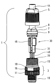
Fig. 1 is a connector with an electric cable in the form of an exploded view;
Fig. 2 is a carrier member in the form of an isometric representation, and
Fig. 3 is a connector sleeve in the form of a sectional representation.
DESCRIPTION OF THE PREFERRED EMBODYMENTS

Figure 1 shows an exploded isometric representation of a connector 1 that is
composed of a connector sleeve 3, a carrier member 30, a sealing insert 7
with a sliding ring 9 and a pressure screw 5.

The connector sleeve consists of connector parts 10, 15 that are attached to
an interior carrier sleeve 20.


CA 02612202 2007-11-23
4

An electric cable 44 with individual electric conductors 46 is inserted into
the
sealing insert 7 and fixed by means of the pressure screw 5 that is screwed
on the connector sleeve 3.

The sliding ring 9 to be pushed onto the sealing insert 7 is provided for
trans-
ferring the shielding potential of a shielded cable when a (not-shown) shield-
ing contacts the metallic sliding ring within the slot 8 such that the sliding
ring
9 transfers the shielding potential to a mating connector via the electrically
conductive pressure screw 5 and the connector sleeve 3.
In addition, a rubber seal 19 is provided on the collar 16 in order to seal
the
screw connection between the pressure screw and the connector part 15.
The pin contacts or socket contacts 40 are respectively crimped on an indi-
vidual electric conductor 46 and inserted into contact chambers 31 in the
carrier member 30.

Figure 2 shows the carrier member 30 to be accommodated within the con-
nector sleeve 3. The carrier member is realized in the form of a cylindrical
member that has two different diameters 35, 36 and is provided with four
axially aligned contact chambers 31 that are arranged circularly and uni-
formly spaced apart from one another.

The diameter of the semienclosed elongated contact chambers 31 is respec-
tively adapted to the coating of the individual electric conductors 46 and the
pin contacts or socket contacts 40 crimped thereon such that the individual
conductors are at least provisionally held in the contact chambers 31 during
the installation until the carrier member 30 is inserted into the connector
sleeve 20.

In order to realize a precisely fitted arrangement of the pin contacts or
socket
contacts, each contact chamber features a positioning recess 32, into which
corresponding positioning projections 42 on the pin contacts or socket con-
tacts 40 can be inserted.


CA 02612202 2007-11-23

Figure 3 shows a sectional presentation of the metallic connector sleeve 3
with the two connector parts 10, 15 that are arranged on a non-conductive
carrier sleeve 20 such that they can be turned relative to one another. In
this
case, the connector part 15 on the connection side is rigidly connected to the
5 carrier sleeve 20 while the connector part 10 on the mating side can be
turned on the carrier sleeve 20, but is held thereon in a captive fashion by
the means of a collar 21.

Both connector parts feature an external thread 12, 17, as well as a collar
11, 21 with a knurling.

The external thread 12 that points to the mating side is provided for produc-
ing a connection with a mating connector 1 while the external thread 17 is
provided for being fixed by means of the pressure screw 5.

When the pressure screw 5 is screwed in, the elastic sealing insert 7 is
pressed against the inner wall of the pressure screw, wherein the electric
cable 44 extending in the sealing insert is non-positively acted upon and pro-
tects the connector from environmental influences.

In addition, the elastic sealing insert 7 is provided with four short
extensions
that are respectively engaged with recesses 29 in the carrier sleeve 20 in
order to fix the sealing insert 7 such that it cannot be turned relative to
the
connector sleeve when the pressure screw 5 is screwed on the connector
sleeve 3.
Two of the four longitudinal ribs 24 are visible on the inner wall of the
carrier
sleeve 20, wherein these longitudinal ribs fix the pin contacts or socket con-
tacts 40 in the contact chambers 31 in a precisely fitted fashion during the
connector installation once the carrier member 30 is inserted into the carrier
sleeve 20. The carrier member is inserted into the carrier sleeve until the
two
stopping edges 28 of the carrier sleeve and the stopping edge 34 of the car-
rier member contact one another.


CA 02612202 2007-11-23
6

In this case, the longitudinal ribs 24 are angled beginning at a stopping edge
28 in the upper third of the carrier sleeve 20 in order to initially position
the
electric contacts.

Another longitudinal rib 27 is provided in the mating region of the carrier
sleeve 20 for the polarization with a corresponding mating connector.

In addition, the ends of the electric contacts 40 on the mating side are
aligned toward the center in a slightly angled fashion within the parallel con-

io tact chambers 31 due to the fact that the coating of the electric
conductors
has a larger diameter than the electric contacts 40, wherein this aspect of
has very positive effects on the contacting properties of pin contacts and
socket contacts.


CA 02612202 2007-11-23

7
List of Reference Symbols

CONNECTOR FOR PRE-FABRICATED ELECTRIC CABLES
1 Connector
2
3 Connector sleeve 10 + 15 + 20
4
Pressure screw
6
7 Sealing insert (element)
8 Slot
9 Sliding ring for shielding

First connector part, front
11 Collar as knurling
12 External thread (with flattening)
13
14
Second connector part, rear
16 Collar as knurling (with flattening)
17 External thread
18
19 Rubber ring seal
Carrier sleeve
21 Collar (for turning part)
22 Through-opening
23 Polarizing rib for contact member
24 Longitudinal ribs for contacts
Inside diameter 1
26 Inside diameter 2
27 Front polarizing means for mating connector
28 Stopping edge TH
29 Receivers


CA 02612202 2007-11-23

8
30 Carrier member
31 Contact chambers
32 Positioning recess
33 Guide groove for polarizing 23
34 Stopping edge TK
35 Diameter 1
36 Diameter 2

40 Pin contactfsocket contact
42 Positioning projection

44 Cable

46 Electric conductor

Representative Drawing
A single figure which represents the drawing illustrating the invention.
Administrative Status

For a clearer understanding of the status of the application/patent presented on this page, the site Disclaimer , as well as the definitions for Patent , Administrative Status , Maintenance Fee  and Payment History  should be consulted.

Administrative Status

Title Date
Forecasted Issue Date 2010-12-14
(22) Filed 2007-11-23
Examination Requested 2007-11-23
(41) Open to Public Inspection 2008-05-24
(45) Issued 2010-12-14
Deemed Expired 2019-11-25

Abandonment History

There is no abandonment history.

Payment History

Fee Type Anniversary Year Due Date Amount Paid Paid Date
Request for Examination $800.00 2007-11-23
Application Fee $400.00 2007-11-23
Maintenance Fee - Application - New Act 2 2009-11-23 $100.00 2009-10-02
Maintenance Fee - Application - New Act 3 2010-11-23 $100.00 2010-09-16
Final Fee $300.00 2010-09-17
Maintenance Fee - Patent - New Act 4 2011-11-23 $100.00 2011-09-14
Maintenance Fee - Patent - New Act 5 2012-11-23 $200.00 2012-10-24
Maintenance Fee - Patent - New Act 6 2013-11-25 $200.00 2013-10-09
Maintenance Fee - Patent - New Act 7 2014-11-24 $200.00 2014-10-29
Maintenance Fee - Patent - New Act 8 2015-11-23 $200.00 2015-10-28
Maintenance Fee - Patent - New Act 9 2016-11-23 $200.00 2016-11-02
Maintenance Fee - Patent - New Act 10 2017-11-23 $250.00 2017-11-10
Owners on Record

Note: Records showing the ownership history in alphabetical order.

Current Owners on Record
HARTING ELECTRIC GMBH & CO. KG
Past Owners on Record
SUNDERMEIER, UWE
Past Owners that do not appear in the "Owners on Record" listing will appear in other documentation within the application.
Documents

To view selected files, please enter reCAPTCHA code :


To view images, click a link in the Document Description column. To download the documents, select one or more checkboxes in the first column and then click the "Download Selected in PDF format (Zip Archive)" or the "Download Selected as Single PDF" button.

List of published and non-published patent-specific documents on the CPD .

If you have any difficulty accessing content, you can call the Client Service Centre at 1-866-997-1936 or send them an e-mail at CIPO Client Service Centre.


Document
Description 
Date
(yyyy-mm-dd) 
Number of pages   Size of Image (KB) 
Description 2007-11-23 8 231
Abstract 2007-11-23 1 22
Drawings 2007-11-23 3 49
Representative Drawing 2008-04-28 1 7
Cover Page 2008-05-13 1 42
Claims 2007-11-23 2 41
Claims 2010-01-06 2 43
Abstract 2010-09-24 1 22
Cover Page 2010-11-29 2 45
Prosecution-Amendment 2009-07-13 2 39
Assignment 2007-11-23 4 99
Prosecution-Amendment 2010-01-06 4 117
Correspondence 2010-09-17 1 30