Note: Descriptions are shown in the official language in which they were submitted.
CA 02612258 2011-03-03
TITLE OF THE INVENTION
VEHICLE WINDOW WITH DEICING FEATURE AND METHOD
[00011 This invention relates to a window, such as a vehicle window (e.g.,
windshield) -having a de-icing features. In certain example embodiments, a
conductive structure is provided on an interior surface of a substrate of the
window,
AC (Alternating Current) tuned to an ice removal frequency is caused to run
through
the conductive structure, and fields generated by AC passing through the
conductive
structure propagate through the substrate to an exterior surface of the window
and can
be absorbed by ice thereby causing the ice to melt and/or be removed from the
window.
BACKGROUND OF THE INVENTION
[0002] Ice tends to build up on the exterior surfaces of vehicle windows in
winter months. Ice build-up may be caused by snow, freezing rain, sleet, or
the like in
different instances. Ice impairs a vehicle driver's ability to adequately see
through a
vehicle window such as a windshield.. Thus, it would be desirable to provide
vehicle
windows with an ice removal feature.
[0003] De-icing structures for vehicle windows are known in the art For
example, see U.S. Patent No. 6,027,075,E
Unfortunately, the de-icing grid structure of the 6,027,075 patent is
provided on the exterior surface of the vehicle window, and thus is
easily susceptible to damage caused by the environment
(e.g., corrosion and/or physical damage).
[0004] In view of the above, there exists a need in the at for a window (e.g.,
vehicle window) that is provided within ice-removal structure or feature that
is not
entirely provided on the exterior surface of the window.
CA 02612258 2007-12-13
WO 2007/008487 PCT/US2006/025981
BRIEF SUMMARY OF EXAMPLE EMBODIMENTS OF THE INVENTION
[0005] In certain example embodiments of this invention, a window such as a
vehicle window (e.g., windshield) is provided with a de-icing
feature/structure. In
certain example embodiments, a conductive structure such as one or more
electrodes
is provided on an interior surface of a substrate of the window. Then, AC
(Alternating Current) tuned to an ice removal frequency is caused to run
through the
conductive structure, and fields generated by the AC passing through the
conductive
structure propagate through the substrate (e.g., glass-substrate of the
window) to an
exterior surface of the window and can be absorbed by ice thereby causing the
ice to
melt and/or be removed from the window. In other words, once the de-icing
circuit is
driven with AC, electromagnetic energy from the circuit is coupled to ice on
the
exterior surface of the window. This electromagnetic energy is absorbed by the
ice
thereby causing ice removal from the window.
[0006] In certain example embodiments, it has been found that an AC
frequency tuned to ice removal is from about 5-40 kHz, more preferably from
about
10-25 kHz, and most preferably from about 10-20 kHz. It has surprisingly been
found
that the use of AC at this frequency causes generation of electromagnetic
energy that
is most efficiently absorbed by ice on the exterior of the window, thereby
resulting in
the most efficient ice removal. A sine wave and/or square wave type of AC may
be
used in different example embodiments of this invention.
[0007] In certain example embodiments of this invention, there is provided a
method of de-icing a vehicle windshield, the windshield comprising an exterior
glass
substrate and an interior glass substrate that are laminated to one another
via at least a
polymer inclusive interlayer, the method comprising: providing at least one
conductor on an interior surface of the exterior glass substrate; applying AC
at a
frequency of from about 5 to 40 kHz to the conductor on the interior surface
of the
exterior glass substrate, so that electromagnetic energy caused by application
of the
AC to the conductor propagates through the exterior glass substrate and is
absorbed
by ice on an exterior surface of the vehicle windshield thereby causing the
ice to melt
and/or be removed from the vehicle windshield.
2
CA 02612258 2007-12-13
WO 2007/008487 PCT/US2006/025981
[0008] In other example embodiments of this invention, there is provided a
window including a de-icing structure, the window comprising: an exterior
substrate
and an interior substrate spaced apart from one another; at least one
conductor
provided on an interior surface of the exterior substrate; and an AC power
source for
applying AC at a frequency of from-about 5 to 40 kHz to the conductor on the
interior
surface of the exterior substrate so that electromagnetic energy caused by
application
of the AC to the conductor is coupled to ice on an exterior surface of the
exterior
substrate thereby causing the ice to melt.and/or be removed from the window.
BRIEF DESCRIPTION OF THE DRAWINGS
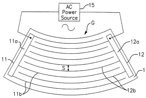
[0009] FIGURE 1 is a schematic diagram of a vehicle window (e.g.,
windshield) including a de-icing feature according to an example embodiment of
this
invention.
[0010] FIGURE 2 is a cross sectional view of the window of Fig. 1.
[0011] FIGURE 3 is a cross sectional view of a window according to another
example embodiment of this invention.
[0012] FIGURE 4 is a cross sectional view of a window according to another
example embodiment of this invention.
DETAILED DESCRIPTION OF EXAMPLE EMBODIMENTS THE
INVENTION
[0013] Referring now more particularly to the accompanying drawings in
which like reference numerals indicate like parts throughout the several
views.
[0014] Figs. 1-2 illustrate an example window (vehicle windshield in this
example case) according to an example embodiment of this invention, where Fig.
1 is
.,a schematic diagram and Fig. 2 is a cross sectional view of the window of
Fig. 1. The
vehicle window of Figs. 1-2 includes first and second opposed glass substrates
1 and
3 with a polymer-based laminating interlayer (e.g.; PVB or the like) 5
provided
therebetween. Glass substrate 1 is the outer glass substrate of the windshield
located
adjacent the exterior of the vehicle, whereas glass substrate 3 is the
interior glass
3
CA 02612258 2007-12-13
WO 2007/008487 PCT/US2006/025981
substrate of the windshield located adjacent the vehicle interior. The glass
substrates
1 and 3 may be perfectly flat, or bent, in different example embodiments 'of
this
invention, and are often heat treated (e.g., thermally tempered and/or heat
strengthened). Windshield or window may have a visible transmission of at
least
about 60%, more preferably of at least about 70%, and sometimes at least 75%,
in
certain example embodiments of this invention.
[0015] The ice removal structure of the Fig. 1-2 embodiment includes comb-
shaped conductors 11 and 12, which include conductive bus bars 1la and 12a,
respectively. The comb-shaped conductors 11 and 12 further include conductive
comb teeth 1lb and 12b, respectively, which extend across a viewing area of
the
window from the bus bars. The conductors (or electrodes) 11 and 12 may be
provided
directly on and contacting the surface of the glass substrate 1 in certain
example
embodiments of this invention, although in alternative embodiments other
layers (e.g.,
dielectric layer or layers such as silicon nitride or the like) may be
provided between
the substrate .1 and the conductors. In making up conductive grid G across a
central
and/or viewing area of the window, moving from top to bottom or vice versa
across
the window, the comb teeth 1lb from the conductor 11 alternate with the comb
teeth
12b from the conductor 12 as shown in Fig. 1 in certain example embodiments of
this
invention. Comb teeth l lb and 12b may be formed of any suitable wiring
material to
make up a conductive grid G, with silver, gold, or the-like being example
conductive
materials. Conductors 11 and 12 may be formed of like materials, which may be
the
same or different than their respective teeth portions. The gap between the
teeth of
conductors l 1 and 12 acts as a capacitor, and waves may oscillate back and
forth
between the two comb-shaped conductors.
[0016] In certain example embodiments, the conductors 11 and 12 may form a
capacitive part of the ice removal circuit. An inductor or choke may be used
to
provide a resonant circuit with broad enough Q factor. When ice 18 is present
on the
exterior surface of the window the circuit picks up an extra resistive
component with
the enhanced capacitive load of the ice. This allows energy to be dissipated
into the
ice and permits the melting of the ice 18. Such an ice mounting circuit may
also
contain an ice and/or water sensing mechanism that may automatically allow
energy
4
CA 02612258 2007-12-13
WO 2007/008487 PCT/US2006/025981
to be delivered from the power source 15 to the circuitry when ice and/or
water is
;detected as being present.
[0017] Fig. 2 illustrates that the conductive grid G formed by the
interspersed
conductors (or electrodes) 11 and 12 is formed on the interior surface- 9 of
glass
substrate 1 (i.e., on the interior surface of the exterior substrate 1). Thus,
the
conductive grid G made up of conductors 11 and 12 is protected from the
surrounding
environment exterior the vehicle by glass substrate 1, and is protected from
the
environment inside the vehicle by interior glass substrate 3 and polymer
interlayer 5.
Thus, the conductive grid G cannot be easily damaged, and cannot be readily
touched
by persons in or around the vehicle.
[0018] In certain example embodiments of this invention, a window such as a
the vehicle window (e.g., windshield) of Figs. 1-2 is provided with de-icing
feature/structure including grid G including conductors 11, 12 and AC power
source
15 electrically connected to the conductors 11, 12.. The conductive structure
including electrodes 11 and 12 is provided on an interior surface 9 of glass
substrate
9. From AC power source 15, AC tuned to an ice removal frequency is caused to
run
through the electrode(s) 11 and/or 12. In accordance with the laws of physics
(e.g.,
Maxwell's Equations), the passing of the AC through the conductors 11, 12
causes
electromagnetic fields to be generated. The electromagnetic fields generated
by the
AC passing through the conductive structure 11, 12 propagate through the glass
substrate 1 and encompass and/or reach an exterior surface 10 of the window
and can
be absorbed by ice 18 thereby causing the ice 18 to melt and/or be removed
from the
window. Stated another way, once the de-icing circuit is driven with AC,
electromagnetic energy from the circuit is coupled to ice 18 on the exterior
surface of
the window. This electromagnetic energy is absorbed by the ice 18 thereby
causing
ice removal from the window via melting and/or delamination.
[0019] In certain example embodiments of this invention, the ice-removal
structure allows the impedance of the circuit to be tuned so that only, or
substantially
only, when ice 18 is present the circuit becomes lossy and dissipates energy
to the ice;
but otherwise the circuit resonates. Thus, the circuit may be termed an ice-
induced
lossy circuit which is not significantly lossy when ice 18 is not present on
the exterior
CA 02612258 2007-12-13
WO 2007/008487 PCT/US2006/025981
surface of the window. This is advantageous in that power consumption may be
made
more efficient.
[0020] In certain example embodiments, it has been found that an AC
frequency from the power source 15 tuned to ice removal is from about 5-40
kHz,
more preferably from about 10-25 kHz, and most preferably from about 10-20
kHz. It
has surprisingly been found that the use of AC at this frequency. causes
generation of
electromagnetic energy that is most efficiently absorbed by ice 18 on the
exterior
surface 10 of the window, thereby resulting in the most efficient ice removal.
A sine
wave and/or square wave type of AC. may be used indifferent example
embodiments
of this invention. In certain example embodiments, a pulsing technique used
may be
the so called chirping mode whereby a sinusoidal wave is modulated by square
pulses.
In certain example embodiments, it has also been found that application of
such AC at
about 300-500 V is particularly- effective at ibe removal.
[0021] In certain example embodiments of this invention, the grid may be
formed by first depositing a continuous conductive layer of Ag, Cr, Au, ITO,
or the
like on the glass substrate 1. The conductive layer can then be laser scribed
into the
two conductors 11 and 12 with a spatial frequency such that line widths (i.e.,
the
width of comb teeth 1 lb and/or 12b) may be no larger than about 200 gm, more
preferably no larger than about 100 m, in certain example embodiments. Such a
gridded system would be difficult to be seen by the naked eye and may even
appear
transparent to a vehicle operator or one exterior the vehicle. In certain
example
embodiments, the spacing "S" between adjacent approximately parallel
conductive
grid members 1lb and 12b may be from about 100 to 800 m, more preferably from
about 100 to 500 p.m, and sometimes from about 125 to 250 gm.
[0022] Fig. 3 is a cross sectional view of a window (e.g., windshield)
according to another example embodiment of this invention, having a de-icing
structure and circuit. The Fig. 3 embodiment is the same as the Fig. 1-2
embodiment
discussed above, except that the grid G of the Fig. 1-2 embodiment is replaced
in the
Fig. 3 embodiment with a continuous conductive sheet or blanket 20 of a
transparent
conductive oxide such as indium tin oxide (ITO) or the like. A transparent
silver or
silver based coating could also be used as the heating conductive coating 20
in
6
CA 02612258 2007-12-13
WO 2007/008487 PCT/US2006/025981
alternative example embodiments of this invention. In certain example
instances, the
conductive coating 20 may be a silver based 1R reflecting layer of a low-E
coating.
The same AC at the frequency discussed above is used and applied to the
transparent
conductive coating 20. In certain example embodiments, the AC is applied
across the
conductive coating 20 using a pair of bus bars or the like. Heat and/or
electromagnetic waves resulting from the AC passing through conductive coating
20
propagate through glass substrate 1 and is/are absorbed by ice 18 thereby
causing the
ice to melt and/or delaminate from the window structure.
[0023] Fig. 4 is a cross sectional view of a window (e.g., windshield)
according to another example embodiment of this invention, having a de-icing
structure and circuit. The Fig. 4 embodiment is the same as the Fig. 1-2
embodiment
discussed above, except that an additional continuous conductive sheet or
blanket 20
of a transparent conductive oxide such as indium tin oxide (ITO) or the like
is
provided on the interior surface, of the other glass substrate 3. Also, in the
Fig. 4
embodiment, the grid G is made up of one conductor and not two spaced apart
combs.
AC is applied so that one terminal of the AC power source 15 is electrically
connected to grid 6 (of a single electrically connected conductor - not two
spaced
apart combs in this example embodiment) and the other terminal of the power
source
15 is electrically connected to the conductive coating 20. Thus, the two
conductors 6
and 20 are provided on different planes, and on opposite sides of the PVB
layer 5.
When this circuit is driven, electromagnetic energy is caused to couple with
ice 18 on
the exterior surface of substrate 1. Again, this technique allows the
impedance of the
circuit to be tuned so that only when ice is present then the circuit becomes
lossy and
dissipates energy to the ice 18, and otherwise the circuit resonates in
certain example
embodiments of this invention. In certain alternatives of the Fig. 4
embodiments,
both conductors 6 and 20 may be of the continuous coating type (e.g., of ITO
or Ag).
[0024] While the invention has been described in connection with what is
presently considered to be the most practical and preferred embodiment, it is
to be
understood that the invention is not to be limited to the disclosed
embodiment, but on
the contrary, is intended to cover various modifications and equivalent
arrangements
included within the spirit and scope of the appended claims.
7