Note: Descriptions are shown in the official language in which they were submitted.
CA 02612647 2007-11-23
FLASHLIGHT
BACKGROUND OF THE 1NVENTION
1. Field of the invention
The present invention relates to a flashlight, more particularly one,
which can be changed in its brightness, and can be switched so as either
to keep on shining or to flash on and off repeatedly, and which has an
LCD display to show the electricity content of the batteries and the
length of time the batteries will last.
2. Brief Description of the Prior Art
Flashlights are usually used to provide illumination in the dark,
thus allowing people to see more clearly in searching, repairing, carrying
out activities or walking. Therefore, flashlights are indispensable.
A conventional flashlight structure includes a hollow main part, a
lamp shade member, a light source fitted to a front end of the hollow
main part,.a switch fitted on the hollow main part, and a rear cover fitted
over a rear end of the hollow main part. The lamp shade member is
positioned around the light source on the front end of the hollow main
part.
Light will be emitted from the front end of the flashlight to
provide illumination when the flashlight is turned on by means of the
switch. However, such flashlights can only produce light for illur ain tion,
CA 02612647 2007-11-23
and don't have other functions therefore they can't attract or satisfy those
people who like to buy and use multifunction products.
SUMMARY OF TBE INVENTION
It is a main object of the invention to provide an improvement on
flashlight to provide people with more convenience. A flashing
according to an embodiment of the present invention includes a main
part, and an LCD display secured on the main part; a controlling device
is secured in the main part, and electrically connected to the LCD display.
The controlling device is an integrated circuit IC1 whose model number
is MC68NC908LV8. The controlling device is connected to a button
fitted on the main part, and a function switching circuit. The flashlight
further comprises an electricity-content checking and measuring circuit
to constantly check and measure the amount of electricity left in the
batteries. Information about the electricity content of the batteries will be
shown on.the LCD display.
The button can be pressed to switch the function switching circuit
so as to change the brightness and the way the light emitting component
emits light; the light emitting component can keep on shining or flash on
and off repeatedly at various frequencies and various brightness values.
Furthermore, information about the brightness and the manner the light
emitting component is emitting light will also be shown on the LCD
2
CA 02612647 2007-11-23
display at the same time.
At the same time, the controlling device will carry out calculation
based on the electricity content of the batteries so as to find out the
length of time the batteries will last, which will also be shown in
numerals on the LCD display. Consequently, the user can change
batteries before the batteries mn out, thus preventing the flashlight from
running out of battery power while it is being used.
BRIEF DESCRIPTION OF THE DRAWINGS
to
The present invention will be better understood by referring to the
accompanying drawings, wherein:
Fig. 1 is a perspective view of a preferred embodiment of the
present invention,
Fig. 2 is a circuit diagram of the controlling device and the LCD
display of the present invention,
Fig. 3 is a circuit diagram of a voltage stabilizing circuit, a
controlling circuit, an electricity-content checking and measuring circuit,
and batteries of the present invention,
Fig. 4 shows a supplementary circuit of LCD 1 shown in Fig. 2,
and
Fig. 5 is a block diagram of the present preferred embodiment.
3
CA 02612647 2007-11-23
DETAILED DESCRIPTION OF THE PREFERRED EMBODIlvIENTS
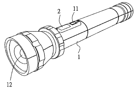
Referring to Fig. 1, a preferred embodiment of a flashlight of the
present invention includes a main part 1, a button 11 on the main part 1,
a light emitting component 12, and an LCD display 2.
The light emitting component 12 is positioned on a front end of
the main part 1, and a lamp covering member is positioned around the
light emitting component 12 and secured to the main part 1. Batteries aYe
held in the main part 1, and a rear cover is joined to a rear end of the
main part 1. The LCD display 2 is secured on the main part 1. The main
part 1 has a controlling device securely positioned therein, and the
controlliung device is electrically connected to the LCD display 2.
Fig. 2 is a circuit diagram of the present invention, wherein the
controlling device is an integrated circuit IC 1 whose model number is
MC68HC908LV8. Switch SW1 is controlled by means of the button 11
shown in Fig. 1. Switch SW1 comprises a function switching circuit
together with Y't 28 and C16. LCD 1 denotes the above-mentioned LCD
display; LCD 1 comprises a liquid crystal display circuit together with a
circuit shown in Fig. 4. Fig. 3 is another circuit diagram of the present
invention, wherein: BT1 denotes the batteries; resistors R14, R16, and a
capacitor C3 of U 1 comprise an electricity-content checkin8 and
measuring circuit; U2 denotes a voitage-stabilizing circuit to stabilize the
power source, and it includes IC2 whose model number is HT7350; DS 1
4
CA 02612647 2007-11-23
denotes the light emitting component; the rest comprise a controlling
circuit for the light emitting component.
In use, the controlling device wi11 constantly check and measure
the amount of electricity left in the batteries through the electricity
content checking and measuring circuit; a terminal check-v shown in Fig.
3 is connected to a terminal check-v shown in Fig. 2 in order for the
electricity content of the batteries to be shown on the LCD display in the
form of bars. At the same time, the controlling device will earry out
calculation based on the electricity content of the batteries so as to find
out the length of time the batteries will last, and the result of the
calculation will also be shown in numerals on the LCD display.
When the button 11 on the main part I is pressed to control the
switch SW1 so as to switch the fanction switching circuit of the
controlling device, signals will be transferred to the integrated circuit
IC 1; thus, the controlling device will control the light emitting
component 12 tlnrough the controlling circuit of the light emitting
component 12. Consequently, the light emitting component 12 will emit
light of certain brightness in a certain manner accordingly; the light
emitting component 12 can keep on shining or flash on and off
repeatedly at various firequencies and various brightness values.
Furthermore, information about the brightness and the way the
light emitting component 12 is emitting light will also be shown on the
LCD display 2 at the same time. In addition, in emergency, the user is
5
CA 02612647 2007-11-23
allowed to move the button 11 to switch the function switching circuit
through the controlling device such that the controlling cnrcuit of the
light emitting component 12 makes the light emitting component 12 emit
very bright light to serve as warning signals.
From the above description, it can be seen that the present
invention is convenient to use, and has the following advantages: the
flashlight of the present invention has the LCD display for showing
information on the electricity content of the batteries as well as the
length of time the batteries will last; the flashlight can be switched to
change the brightness values, and can be switched so as to shine in either
one of various ways, e.g. flashing on and off repeatedly at a certain
frequency, and continue emitting light; furthermore, the flashlight can be
to switched so as to produce very bright light, which can serve as
warning signals in emergency.
20
6