Note: Descriptions are shown in the official language in which they were submitted.
CA 02612782 2007-11-29
HEAT EXCHANGE SYSTEM
FIELD OF THE INVENTION
The present invention relates to heat transfer and more particularly, relates
to an
underground heat exchange system.
BACKGROUND OF THE INVENTION
The use of the geothermal energy to providing heating or cooling has been
known in
the art. The low intensity temperature maintained by the mantle of the earth
may be used to
provide a sump for cooling or heating absorption when the air temperature is
either higher or
lower than the temperature of the earth mantle.
In rural areas, there are frequently buildings which need to be heated to a
certain
degree, but not necessarily to the temperature that a typical residence would
require. For
example, barns, storage buildings and the like are outbuildings which require
a source of
heat, particularly in very cold climates. Also, some industrial buildings such
as airport
hangars have the same requirement. To date, traditional forms of heat such as
furnaces have
been utilized.
SUMMARY OF THE INVENTION
It is an object of the present invention to provide a method and apparatus for
the
heating of such buildings.
According to one aspect of the present invention, there is provided a system
for
heating a building, the system comprising a well, a plurality of pipe loops in
a floor of the
building, a closed loop heat exchange system connected to the pipe loops, the
heat exchange
system comprising an up pipe and a down pipe within the well and connected to
the pipe
loops, the up pipes and down pipes being connected to a heat exchange portion
of a metallic
-1-
CA 02612782 2007-11-29
material located in a lower portion of the well.
BRIEF DESCRIPTION OF THE DRAWINGS
Having thus generally described the invention, reference will be made to the
accompanying drawings illustrating an embodiment thereof in which:
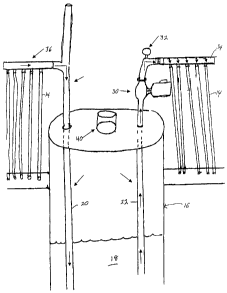
Figure 1 is a schematic view of a portion of a system according to the present
invention;
Figure 2 is a schematic side view of a circulating pump and entry into the
pipes; and
Figure 3 is a schematic side view of the heat exchange portion of the system.
DETAILED DESCRIPTION OF THE INVENTION
Referring to the drawings in greater detail and by reference characters
thereto, there
is illustrated in Figure 1 the floor of a building such as a garage or the
like. Such buildings
could include storage garages for large equipment such as snow removal
equipment.
The garage floor is generally designated by reference numeral 10 and the
building
will typically have a garage door 12 located in one of the wall thereof.
Although the size is
irrelevant, such buildings will typically have a floor area of up to 2,000 sq.
feet or even
more.
As shown in Figure 1, there is provided a plurality of pipe loops 14 which are
set
within the concrete as the floor is poured. Again, such an arrangement is
known in the art.
The system will include a well generally designated by the reference numeral
16
which is dug to a substantial depth. Typically, the well may have a depth of
100 feet or even
more. The well 16 will be filled with well water 18.
Placed within well 16 is down pipe 20 which is preferably of a plastic
material and an
-2-
CA 02612782 2007-11-29
up pipe 22 which likewise is preferably of a plastic material. At the bottom
of the well,
there is provided a U-shaped section 24 which functions as the heat exchanger
portion of the
system. U-shaped section 24 is preferably of a metallic material and most
preferably is
formed of a stainless steel material with a plurality of blades 18 extending
between the two
arms of the U-shaped section 24 to enhance the heat transfer.
A circulation pump 30 is provided at the top of the well. Circulation pump 30
is
relatively small and can be rated as low as 1/6 horsepower (125 watts). A
pressure meter 32
is provided on the line after circulation pump 30.
A distribution manifold 34 is provided to distribute the liquid to pipe loops
14.
Similarly, a return manifold 36 is designed to collect the fluid after passing
through pipe
loops 14.
Preferably the heat exchange liquid is a water mix such as water glycol or
methanol
in the closed circuit loop.
Provided at the top of well 16 is a water pipe 40.
It will be understood that the above described embodiment is for purposes of
illustration only and that changes and modifications may be made thereto
without departing
from the spirit and scope of the invention.
-3-
