Note: Descriptions are shown in the official language in which they were submitted.
CA 02613158 2007-11-28
A FLOATABLE DOCK MOORING ARTICLE
This application is a division of Canadian Patent Application No. 2,541,655
filed April 3, 2006 for A Floatable Dock Mooring Article.
FIELD OF THE INVENTION
[00011 The present invention relates to a floatable dock mooring article that
can
rise and fall with a water level. More specifically, the article relates to a
mooring
member which is movably connected to a portion of a dock pipe, and generally
has
a radially outward set projection which is capable of engaging a radially
inward
projection of a float so as to either locate the float at a predetermined
location
along the vertical height of the mooring member, or to permit the float to
rise with
the water level and upon engaging the outward set projection to cause the
mooring
member to rise along the dock pipe.
BACKGROUND OF THE INVENTION
[0002] Heretofore, watercrafts such as boats, canoes, jet skis, rafts etc.
have
generally been moored to a dock pipe as by a rope. If tightly bound, the rope
would prevent the watercraf.t from rising as the water level rises, thus
causing the
watercraft to tip and possibly sink. Alternatively, if the rope was loosely
bound,
the rope would rise with increasing water height and come off the dock pipe
causing the watercraft to drift away and even be lost.
[0003] Prior art mooring devices are set forth in the following U.S. Patents:
1
CA 02613158 2007-11-28
[0004] U.S. Patent Re 27,050 relates to a reportedly force absorbing system
adapted to be used with a moored vessel including a base affixed to the dock,
a
pair of yielding elements extending from the base and a pair of vertically
disposed
bumper sections attached to respective yielding elements. The bumper sections
are suspended in the water with clearance from the bottom and receive support
from the dock from above the water line.
[0005] U.S. Patent No. 3,001,371 relates to an offshore drilling rig mooring
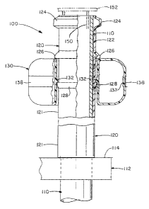
and
more particularly to a floating mooring buoy especially adapted for a floating
attachment to an offshore drilling rig support.
[0006] U.S. Patent No. 3,430,598 relates to a mooring device for mooring a
boat having an upright pair of shafts adapted to be inserted upright into the
lake
bottom in spaced parallel relation to one another, with the upper portions of
the
shafts projecting above the surface of the lake, a pair of air tight
containers acting
as floats, said containers each having a vertical bore to slideably receive
the said
shafts, rope attaching means on each of said containers, said shafts being
spaced
further apart from one another than the length of said boat, rope means
attached
to the front of the boat may be attached to one of said containers and the
rope
means attached to the rear of said boat may be attached to the other of said
containers, and said container will reportedly float upward and downward on
said
shaft in response to changes to the lake surface while maintaining said boat
moored between said shaft.
[0007] U.S. Patent No. 3,486,342 relates to a mooring bumper device having a
floatable base floating on a water surface and loosely surrounding a mooring
pile
for up and down movement thereon under the action of tide and wind. The
bumper device has an axial opening through which the mooring pile extends and
2
CA 02613158 2007-11-28
the upper terminal end of the bumper device is flat and horizontal. A metal
hitch
ring provided with a plurality of eyes to one or more of which a boat mooring
line is
attached is freely seated on the flat upper end of the bumper device in
surrounding
relation to the mooring pile providing relative rotation between the bumper
device
and the hitch ring. The eyes on the hitch ring lie inwardly of the peripheral
edge of
the flat upper end of the bumper device.
[0008] U.S. Patent No. 3,842,779 relates to a boat mooring device comprising a
bow-shaped frame member with a cable or the like attached thereto and with a
slidable member supported on said cable and secured to a boat so that as the
movement of the water causes the boat to move up and down, as well as in other
directions, the sides of the boat will bear against the slidable member and
reportedly will move it to correspond to the up and down movement of the boat
and thereby prevent scuffing and damage to the boat.
[0009] U.S. Patent No. 4,480,576 relates to a boat mooring arrangement which
reportedly permits the boat to rise and drop vertically with tides or wave
action,
but which constrains the boat from lateral movement relative to a fixed dock
or
pier. A pair of cylindrical posts are affixed to the dock or pier at spaced-
apart
locations and extend vertically downward therefrom for a predetermined
distance
below the surface of the water. Associated with each of these posts is a
carriage
assembly comprising a U-shaped collar having rollers journaled for rotation
across
the spaced-apart legs of the U-shaped collar. The carriage assemblies
reportedly
cooperate with the exterior surface of the posts and ride up and down with
respect
to the posts when the carriage assemblies are fastened to the boat to be
moored
by suitable tie lines and changes in water level are encountered.
3
CA 02613158 2007-11-28
[0010] U.S. Patent No. 5,050,521 relates to a boat mooring apparatus to allow
for ease of travel up and down dock piling posts in such a fashion that it is
free to
move vertically with changes in tide. It comprises a mooring line roller and
chafe
resistor which includes a ribbed tube and spools or rollers mounted on tube
and
fitted over the mooring lines. It is fitted on the dock lines and around the
dock
posts and tied to the cleats of a vessel. to be moored.
[0011] U.S. Patent No. 5,301,628 relates to a docking post which includes a
tubular housing having a front wall, including an elongate slot directed
through the
front wall longitudinally aligned relative the housing and parallel to the
housing axis,
with the housing having a rear wall mounted to an associated mooring post. A
first
tube is mounted within the housing, having a securement ring thereon, with a
second tube positioned below the first tube having a length adjusted to
accommodate a predetermined length between a boat water line and a boat
securement cleat. A third buoyant tube is mounted below the second tube to
effect displacement of the first and second tube to reportedly effect
displacement
of the first and second tube relative to rising and lowering tides and water
level
relative to the tubular housing.
[0012] U.S. Patent No. 5,467,727 relates to a hollow toroidal member of high-
strength material for reportedly withstanding mooring loads and has a central
opening which slips over a mooring pile. A reinforcing ring is preferably
secured in
the core of the member to provide additional load-bearing capability to the
device.
A pair of diametrically opposite mooring openings are formed in the member and
ring each opening for receiving a boat mooring line, the openings in the
member
and ring being aligned. The member is preferably molded with its core in fluid
isolation from the ambient atmosphere to provide buoyancy. In the alternative,
the
4
CA 02613158 2007-11-28
core is filled with flotation material. A pair of apertured legs may be used
in place
of the openings in the member for securing the mooring lines thereto.
[0013] U.S. Patent No. 5,937,781 relates to a watercraft mooring device which
reportedly permits the watercraft to rise and drop vertically with the water
level
and which provides both direct shock absorption between the watercraft and the
fixed mooring point, such as the pier or piling, and protection against
scraping
between the watercraft and the fixed mooring point. A floating tube is
provided,
which is designed to loosely fit over and around the fixed mooring point and
which
provides one or more attachment grooves for holding an attachment rope, cord
or
cable in place. The provided floating tube includes one or more securing hooks
for
securing the attachment rope, cord or cable when it is not needed to moor the
watercraft. By providing a floating mooring device, the watercraft is
permitted to
maintain the same relative distance between the watercraft and the fixed
mooring
point, providing a device for protecting a watercraft from undesirable contact
with
other mooring structures.
[0014] U.S. Patent No. 6,123,045 relates to a device for dock storage and boat
accessible retrieval of a boat docking line. The device generally comprises a
pedestal that is fixedly attachable to a dock and an arm rotatably attached to
the
upper end of said pedestal, said arm including a hook disposed at the distal
end of
said arm for receipt of a docking line.
SUMMARY OF THE INVENTION
[0015] A dock mooring member that slidably fits around a dock pipe rises and
falls with the level of the water thu.s allowing a watercraft such as a boat
to rise
and fall with the water level and not tip, sink or be released from the dock.
A
floatable dock mooring article comprising the mooring member generally has a
CA 02613158 2007-11-28
flange at the upper portion thereof and a floatation device located beneath
the
flange.
[0016] The mooring member generally has at least one radially outward set
projection and the floatation device that desirably is a float has a radially
inward
projection with the mooring member set projection and the float inward
projection
being capable of engaging each other so as to either act as a set location
along the
mooring member to prevent the float from settling or, alternatively, to keep
the
float from rising above the set projection so that upon further rising of the
water
level, the float will cause the mooring member to rise along the dock pipe.
[0017] In one aspect of the present invention a floatable dock mooring article
is
described, comprising a mooring member having at least one radially outward
set
projection, said at least one radially outward set projection having an
external
diameter; said mooring member adapted to have an internal diameter greater
than
the outer diameter of a dock pipe and being capable of contacting and resting
on a
portion of a dock, said mooring member adapted to be movably connected to a
portion of said dock pipe; a flange, said flange located at the top portion of
said
mooring member; an optional float retention flange located below said mooring
member flange and above said mooring member outward set projection; and a
float
operatively connected to said mooring member, said float having at least one
radially inward projection having an internal diameter, said mooring member
projection external diameter being greater than said float inward projection
internal
diameter, and said mooring member set projection being capable of engaging
said
float inward projection.
[0018] In a further aspect of the present invention a floatable dock mooring
article is described, comprising a mooring member having a) radially outward
set
6
CA 02613158 2007-11-28
projection or b) a radially inward recess, or both said a) and said b), said
at least
one radially outward set projection having an external diameter, said radially
inward
recess having an internal diameter, said mooring member adapted to have a
minimum internal diameter greater than the outer diameter of a dock pipe and
being
capable of contacting and resting on a portion of a dock, said mooring member
adapted to be movably connected to a portion of said dock pipe;a flange, said
flange located at the top portion of said mooring member; an optional float
retention flange located below said mooring member flange and above said
mooring
member outward set projection; and a float operatively connected to said
mooring
member, said float having at least one radially inward projection having an
internal
diameter, wherein when present said mooring member radially outward set
projection external diameter is greater than said float inward projection
internal
diameter, and said mooring member radially outward set projection being
capable of
engaging said float inward projection, and wherein the float radially inward
projection engages said mooring member radially inward recess when present so
that upon upward movement of said float, said mooring member is moved
therewith.
BRIEF DESCRIPTION OF THE DRAWINGS
[0019] FIG. 1 is a side elevation view, in partial cross-section, of a
floatable dock
mooring article according to the present invention;
[0020] FIG. 2 is a side elevation view, in cross-section, of another floatable
dock
mooring article containing an inflatable float;
[0021] FIG. 3 is a partial side elevation view of another embodiment of the
present invention showing only the floatable dock mooring article;
[0022] FIG. 4 is a side elevation view, in partial cross-section, of the
floatable
dock mooring article having an extension pipe;
7
CA 02613158 2007-11-28
[0023] FIG. 5 is a side elevation view, in partial cross-section, of another
embodiment of the floatable dock mooring article havirig a set projection on
the
mooring member;
[0024] FIG. 6a is a limited cross-section view of another embodiment of FIG. 5
wherein the float radially inward projection is located below the mooring
member
radially outward set projection;
[0025] FIG. 6b is a limited cross-section view of another embodiment of FIG. 5
wherein the float has a radially inward recess that is capable of engaging the
mooring member radially outward set projection;
[0026] FIG. 6c is a limited cross-section view of another embodiment of FIG. 5
wherein the radially outward float projection is capable of engaging a
radially
inward mooring member set recess;
[0027] FIG. 7 is a side elevation view, in partial cross-section, of one
embodiment of a floatable dock mooring article according to the present
invention;
[0028] FIG. 8 is a side elevation view, in cross-section, of one embodiment of
a
mooring member; and
[0029] FIG. 9 is a side elevation view, in cross-section, of a further
embodiment
of a mooring member.
DETAILED DESCRIPTION
[0030] Referring to FIG. 1, a watercraft dock pipe 10 supports, in any
conventional manner, dock 12 located above a body of water such as a lake, a
river, a bay, etc. As shown in FIG. 1, a portion of dock pipe 10 generally
extends
a distance above the dock and mooring ropes, etc., have been connected thereto
to
retain a watercraft. Watercraft generally includes boats, canoes, jet skis,
rafts, and
the like.
8
CA 02613158 2007-11-28
[00311 Floating dock mooring article 1 is designed to be placed over and about
dock pipe 10 which extends above dock 12. Mooring article 1 comprises various
types of mooring members 20 such as pipes, tubes, ducts, and the like with the
requirement that they are generally in the form of an annulus having an inside
diameter and an outside diameter spaced apart therefrom. While the shape of
the
annulus is generally circular, it is to be understood that any shape can be
utilized,
such as elliptical, egg-shaped, pear-shaped, square tubing, and the like.
Mooring
member 20 can be made out of any suitable material such as lightweight metal,
e.g. aluminum or titanium, but desirably has a specific gravity of less than
1Ø
Suitable materials include various types of wood, plastic, fiberglass,
composites,
and the like with plastic generally being preferred. Plastics include
polyvinyl
chloride, polyester, polystyrene, nylon, various polyolefins such as
polyethylene or
polypropylene, and the like with polyvinyl chloride being preferred.
[0032] Mooring member 20 naturally has an inside diameter which is greater
than the outside diameter of dock pipe 10 so mooring member 20 can easily be
inserted thereover and freely rotate and/or elevate thereabout. Generally
mooring
member 20 has a lower flange 23 which contacts dock floor 14 and permits the
member to rest thereon. Upper flange 24 is generally located at the upper
vertical
end portion of the pipe and preferably at the very end thereof. Flanges 23 and
24
can be attached, secured, etc. in any manner, as by screws, bolts, and more
desirably is adhered by an adhesive such as styrene, epoxy, or acrylate and
the
like. The length of mooring member 20 can vary as from about a foot to any
desired length such as about 10 or 12 feet with generally from about 2 to
about 6
or about 8 feet desired. Naturally, the mooring member can be cut to any
desirable
length to compensate for a rise in the level of a body of water.
9
CA 02613158 2007-11-28
[0033] An important aspect of the present invention is the utilization of a
flotation device 30 attached to mooring member 20 at any desired location. The
float is made of a material which is lighter than and preferably substantially
lighter
than water and can be wood, plastic, foam, composite materials and the like.
Float
30 can be rigid, semi-rigid, resilient or semi-resilient, or flexible. If the
foam is
made from a polymer, it can be closed-cell, or if an open cell structure
preferably
contains a continuous layer of a skin thereon to prevent water from entering.
Suitable flotation devices 30 include various foams of polyurethane,
polystyrene
and the like. As with the flanges, flotation device 30 can be applied or
secured to
mooring member 20 in any conventional manner as through the use of flanges
located on the top and bottom of the float and secured to the mooring member,
but
preferably is secured to the mooring member through the use of an adhesive
such
as styrene, epoxy, or acrylate, and the like.
[0034] The shape of float 30 is generally not important so long as it has
enough
buoyancy so that when a rising water level of a lake, etc. contacts the float,
it will
raise up and cause mooring member 20 to float. While the float 30 is generally
cylindrical as shown in FIG. 1, it can be in the form of a truncated frustum
as
shown in FIG. 3, wafer shaped, ball-shaped, and the like.
[0035] Another type of flotation device shown in FIG. 2 is an inflatable
device
made out of rubber or some other strong flexible material such as plastic and
filled
with a fluid, preferably air.
[0036] Regardless of the size, shape or type of flotation device, it can also
generally serve as a bumper guard as to protect the side of a boat from
striking a
dock and being damaged.
-
CA 02613158 2007-11-28
[0037] The float 30 can generally be located in any position on mooring member
20 but desirably the bottom portion of the mooring member is avoided in order
to
prevent damage to the float by contact with the dock and also to allow a
mooring
device e.g., a rope to be attached thereto. Similarly, the float is not
located at the
top portion of the mooring member so when desired a mooring device can be
attached thereto. Desirably, the float is located from about 10% to about 90%
and more desirably from about 20% to about 80% of the mooring member height.
Naturally the height of the float is generally small in comparison to the
height of the
dock mooring member 20 and is from about 1 or about 2 inches to about 6, about
8, or about 10 inches or even about one foot. Regardless of where the float is
attached or adhered to mooring member 20, the portion below float 30 is
referred
to as lower leg 21 whereas the portion above the float is referred to as upper
leg
22.
[0038] A mooring device such as a rope secures the watercraft to dock mooring
member 20 which in turn freely rotates and/or elevates about dock pipe 10. In
use, as the water level rises as in a flood, the water will generally contact
float 30
and cause the mooring member to rise. Thus, the mooring device such as a rope
will also rise and generally maintain an even relationship with the watercraft
and
thus does not cause it to tip and/or sink. If the rope is secured to upper leg
22,
upper flange 24 prevents the rope from coming off the upper end of mooring
member 20. Alternatively, if the rope is attached to lower leg 21, lower
flange 23
will prevent the rope from being disengaged from mooring member 20. In order
to
gain an additional height advantage, float 30 is desirably located in an
intermediate
vertical portion of mooring member 20 or can be located near the top portion
of a
mooring member. The higher location provides an additional safety factor in
that
the water level must rise the additional distance to the upper float location
before
the pipe will commence rising up along dock pipe 10. For example, if flotation
11
CA 02613158 2007-11-28
device 30 is located three feet above lower flange 23 or the bottom of mooring
member 20, the water level must rise an additional three feet before it
contacts
flotation device 30 whereupon mooring member 20 commences rising. It should
thus be apparent that floatable member article 1 of the present invention can
accommodate large rises in the water level of a lake, river, etc.
[0039] Another embodiment of the invention relates to floatation device 30,
which is not secured to mooring member 20, but rather freely slides up and
down
the mooring member. Such a floatation device can simply have an internal
diameter which is larger than the external diameter of mooring member 20, but
smaller than the outer diameter of flange 24 as in FIG. 3. Alternatively float
30
can be secured to sleeve 40 (see FIG. 2) preferably made out of light-weight
material such as a composite or plastic as in the form of a cylinder. While
the
entire outer portion of the sleeve could have the same radius, desirably the
upper
and lower portions of the sleeve have projections or flanges so that a rope,
etc.,
can be secured thereabout. Since sleeve-floatation device 40 freely rotates
and/or
elevates about mooring member 20, it will normally reside on dock floor 14.
However, upon a rising water level, the sleeve-flotation device will rise
upwardly on
dock pipe 10 until the top portion of the sleeve contacts upper flange 24 at
which
time mooring member 20 will commence rising.
[0040] Another embodiment of the present invention is shown in FIG. 4. which
allows an even further rise in the height of dock mooring article 1. Mooring
member 20 can be any of the various arrangements as shown in FIGS. 1, 2, or 3.
An extension pipe 50 generally having a hollow or solid cylindrical shape is
inserted
or resides inside dock pipe 10 which has an internal opening therein. The
extension pipe can be made of the same types of materials as set forth above
with
respect to dock mooring member 20 such as lightweight metal, but preferably is
12
CA 02613158 2007-11-28
plastic. The top of extension pipe 50 has flange 52 secured thereto and the
same
can be in the form of any shape such as a disk or a handle as shown in FIG. 4.
However, extension pipe 50 is desirably longer than the length of mooring
member
20 which resides on dock 12. That is, the extension pipe in being located
within
the dock pipe can extend several feet beneath the dock. Thus, as the water
level
rises and contacts float 30 and causes the same to raise, dock mooring member
20
will contact top flange 52 of the extension pipe and cause the extension pipe
to
rise. Even though the bottom end of dock mooring member 20 can rise above the
top dock pipe 10, extension pipe 50 can still be located within the dock pipe,
thereby maintaining a secure engagement of the watercraft.
[0041] In view of the above description, it should be apparent that floating
dock
mooring article 1 of the present invention is very versatile. For example,
flotation
device 30 can be located in any position along the length of dock mooring
member
20 provided that a mooring line can be located either above or below the
float.
Multiple flotation devices can be utilized although a single float is
generally
preferred. The length of dock mooring member 20 can be long or short and
optionally, can be utilized in association with extension pipe 50 to further
extend
the vertical range of usefulness of the dock mooring member. Moreover,
couplings
can be utilized to join one portion of mooring member 20 to another portion
and/or
to enlarge or reduce the diametrical size thereof.
[0042] Another embodiment of the present invention relates to the mooring
member and the float having projections on generally the vertical sides
thereof so
that depending upon the location of the projections with respect to one
another,
mechanical engagement of the float with the mooring member can be at a
predetermined height, or the float will be free to rise to a vertical height
until it
engages the mooring member projection that will cause the mooring member to
rise
13
CA 02613158 2007-11-28
up along the dock pipe. Thus, the float, for various reasons including safety
and
freedom to walk along the dock floor can be maintained above the dock floor.
Alternatively, upon an increase in the water level such that when the water
contacts the float, the float will rise and engage the mooring member
projection
and raise the mooring member up along the dock pole and thus extend the
overall
height at which the mooring member is secured to the dock pipe.
[0043] An embodiment of the preceding paragraph is shown in FIG. 5 wherein
the floatable dock mooring article is generally indicated by the numeral 100
and
comprising dock pipe 110 that extends through or is connected to dock 112 and
preferably floor 114 thereof. As with the previously described embodiments,
mooring member 120 is connected to and preferably fits and slides over dock
pipe
1 10 and generally freely rotates thereabout. The bottom of mooring member 120
resides upon a portion of a dock, such as dock floor 114. Mooring member 120
has lower leg 121 and upper leg 122 generally indicated as being respectively
below or above mooring member set projection 128. As with the above
embodiments set forth herein, mooring member 120 generally contains upper
flange 124 at the upper end portion thereof. The flange through a securing
medium such as a rope serves to retain a watercraft connected to the mooring
member.
[0044] In order to maintain floats 30 such as shown in FIGS. 2 and 3, or float
130 such as shown in FIG. 5 at a predetermined (set) vertical or height
location
with respect to mooring member 120, the mooring member has a radially outward
set projection 128 that has an external diameter and is located at a
predetermined
vertical distance or height on the mooring member. Radially outward set
projection
128 is essentially a lateral extension of the mooring member and can be a
ridge, a
rim, a ring, a bulge, a protrusion, a ledge, and the like that can be square,
rounded,
14
CA 02613158 2007-11-28
angular, etc. shaped. Radially outward set projection 128 can be continuous
and
thus extend entirely (that is 3600) about the entire mooring member or it can
be
discontinuous extending for any desired arc of a circle and one or a plurality
of
such outward set projections can exist. The outward distance of projection 128
is
such that it can engage a radially inward projection 132 of float 130 and
either
retain the float in a set position (that is at a predetermined fixed height)
or be
raised by the float from under the set projection so that upon contact with
the
underside of the projection the float will cause the mooring member to rise.
[0045] In one embodiment, such as shown in FIG. 9, mooring member includes
two or more outward set projections 128 located at different vertical or axial
heights, located at any desired distance from each other. Multiple outward set
projections 1 28 allow connection of multiple floats 130 to the mooring member
to
provide greater ability of flotation. The use of multiple floats also provides
a larger
surface area that can serve as a fender and prevent a boat or other object
from
striking the dock.
[0046] Float 130 has a radially inward projection 132 located on a generally
vertical inner side surface of the float that extends laterally inward
thereof. The
generally vertical side surface of float 30 has a diameter which is greater
than the
external diameter of mooring member outward set projections 128 so that the
float
is free to rise upward or downward along mooring member 120. Radially inward
projections 132 can be defined in the same manner as with respect to outward
set
projections 128 and thus can be ridge, a rim, a ring, a bulge, a protrusion, a
ledge,
and the like that can be square, rounded, angular, etc. shaped and furthermore
can
be continuous such that it extends a full 360 about float 130 or can be
discontinuous and of any arcual length and can be one or a plurality of such
inward
projections. The shape of the radially inward projection is preferably
CA 02613158 2007-11-28
complementary to the outward set projection in one embodiment. In one
embodiment, the design of the mooring member 120 and float 130 allow the same
to snap together, in some cases making separation difficult or impossible
without
destroying the functionality of the mooring article, depending on the
configuration
of the set projections utilized.
[0047] In a preferred embodiment of the present invention, the mooring member
radially outward set projection diameter is greater than the float radially
inward
projection internal diameter so that mooring member outward set projection 128
can engage float inward projection 132. In the embodiment as shown in FIG. 5,
float projection 132 is located above mooring member s=et projection 128 and
thus
the height of float 130 is set at a predetermined distance above the bottom of
mooring member 120 which generally resides upon floor 1 14 of dock 112. As the
level of water rises it will contact float 130 and cause the same to rise
about
mooring member 120. Float 130 can rise until it contacts upper flange 124 at
which point it will cause mooring member 120 to rise along dock pipe 110.
Optionally, retention flange 126 can exist on upper leg 122 of the mooring
member
at a position between the top of float 130 but below upper flange 124. In this
embodiment, float 1 30 will rise until it contacts retention flange 126 at
which time
it will cause the mooring member to rise. In another embodiment, when
retention
flange 126 is set at a location such that it contacts the top of float 130
when
inward projection 132 resides upon outward set projection 128, the float will
be
locked into position. In this embodiment, as the water level contacts float
130
contained by the retention flange, the float will immediately cause mooring
member
126 to rise. Thus, depending upon the location of optional retention flange
126 or
mooring member upper flange 124, the effective extension height of mooring
member 120 can be predetermined so that the mooring member serves as an
additional height securement of a rope or the like to a watercraft.
16
CA 02613158 2007-11-28
[0048] FIG. 6a represents a partial cross-sectional view of mooring member and
float as set forth in FIG. 5 but wherein said float inward projection is
located below
mooring member outward set projection 128. In this embodiment, float 130 can
reside upon dock floor 114. Upon a rise of the water level, float 130 will
freely
slide and rise up along mooring member 120 until float inward projection 132
contacts the bottom of mooring member outward set projection 128 at which
point
the float will cause mooring member 122 to rise.
[0049] The embodiment of FIG. 6a is desirable for situations wherein the float
130 can also be utilized as a dock bumper guard with regard to the watercraft
vehicle.
[0050] The embodiment of FIG. 6b is similar to that of FIG. 5 except that
float
30 instead of having a radially inward projection, has a radially outward
recess 1 34
that engages (as by a snap fit) outward set projection 128. However, the float
of
FIG. 6b still has a vertical side inward portion located above and below
mooring
member outward set projection 128 and thus can be considered as having two
radially inward float projections 132. In this embodiment, float 130 is fixed
at a
predetermined height, is not free to rise above mooring member set projection
128
as in the embodiment of FIG. 5, and also cannot fall below the set projection
as in
the embodiment of FIG. 6a. In this embodiment once a rising water level
contacts
float 130 it will immediately cause mooring member 120 to rise.
[0051] The embodiment of FIG. 6c is similar to that of FIG. 6b except that the
float has a radially inward projection 132 and unlike the embodiments of FIG.
5, 6a
and 6b, mooring member 120 has a radially inward recess 129. In order to apply
float 130 to the mooring member, it must be slid up along the bottom leg of
the
17
CA 02613158 2007-11-28
mooring member until inward projection 132 resides within mooring member
recess
129. A frictional engagement of a float thus exists with the mooring member as
it
is slid up lower leg and generally snaps into recess 129. The float inward
projection thus must be made of a resilient or flexible material while the
remaining
portion of the float can also be made with such material or desirably of a
more rigid
material. The operation of the embodiment of FIG. 6c is similar to that of the
embodiment of FIG. 6b in that the float is set at a predetermined height along
the
length of the mooring member and the dock flooring. As the water level rises,
upon contact with float 130 it will cause mooring member 120 to rise.
[0052] Both embodiments of FIGS. 6b and 6c can contain the optional retention
flange 1 26 at any location above the float but below upper flange 1 24.
[0053] The materials of the embodiments of FIGS. 5, 6a, 6b, and 6c are
generally the same as set forth hereinabove and thus are fully incorporated by
reference. By way of brief summary, mooring member 128 is preferably made of
plastic such as polyvinyl chloride or polyolefin with polyethylene, and
especially
high density polyethylene being preferred. With respect to the float, it can
be rigid,
semi-rigid, resilient, or flexible. The float can contain various foams
therein such as
polyurethane or polystyrene or the float can simply be a layer of plastic
containing
air therein, e.g. a hollow float, with the plastic preferably being polyvinyl
chloride or
low density polyethylene.
[0054] The embodiments of FIG. 5, 6a, 6b and 6c can optionally further
incorporate an extension pipe 150 shown in FIG. 4 generally having a hollow or
solid cylindrical shaft which is inserted into and resides within dock pipe
110. The
top of extension pipe 150 has flange 152 secure thereto and the same can be in
the form of a handle, a cylindrical horizontal rod, a horizontal disc, and the
like. As
18
CA 02613158 2007-11-28
noted above, an important advantage of extension pipe 150 is that is it
desirably
longer in length than mooring member 120 and extends in dock pipe below the
dock floor or below an average water level, or even can extend down to the
bottom of a body of water in which the dock pipe resides. Thus, as the water
level
rises and contacts float 130 and causes mooring member to rise, extension pipe
1 50 will also rise. However, once the bottom of mooring member 120 is above
the
top of the dock pipe, the extension pipe will still be inserted within the
dock pipe
and provide still greater extension height to secure a watercraft to the
mooring
member. As set forth above, extension pipe 150 can be made of materials such
as
light weight metal, wood, etc., but preferably is plastic.
[0055] In yet a further embodiment of the present invention, a kit or assembly
is
provided including various components that, when assembled, form a floatable
dock mooring article 1. As shown in FIG. 7, the assembly includes a dock pipe
10,
such as described hereinabove. The dock pipe 10 can be any length, and
generally
has a portion that extends about 2 to about 6 feet, and preferably from about
3 to
about 5 feet above the surface of the floor 14 of dock 12. The dock pipe 10 is
connected to dock 12 through a suitable bracket or clamp 16, preferably via
one or
more fasteners 1 7. Dock pipe 10 may or may not provide any support for dock
12
and may only be used in conjunction with the float dock mooring article in
some
embodiments.
[0056] Extension pole 60 is connected to dock pole 10 and generally has an
inner diameter greater than the outer diameter of dock pole 10 and fits over
and
around dock pole 10. Extension pole 60 is either movably or fixedly connected
to
dock pole 10 in order to provide a desired form or action to the floatable
dock
mooring article. When movably connected, extension pole 60 is movable in a
direction parallel to a longitudinal axis of the dock pole 10, i.e. in a
substantially
19
CA 02613158 2007-11-28
vertical. direction as shown in FIG. 7. Extension pole 60 includes an upper
flange
64 similar to upper flange 24 and having an outer diameter greater than a
minimum
inner diameter of the mooring member 120 in order to prevent mooring member
120 from becoming displaced from the assembly at an extremely high water
level,
such as above the upper end of extension pole 60. Extension pole 60 has a
lower
end generally disposed against a portion of the dock 12 such as dock floor 14
or a
portion of bracket 16. Extension pole 60 has a length generally from about 2
to
about 6 feet, preferably from about 3 to about 5 feet. Mooring member 120 is
formed as described hereinabove generally including one or more floats 130 as
described herein. As is also described hereinabove, a rope or other object can
be
connected to mooring member 120 and is allowed to rise along with mooring
member 120 as a water level rises. Float 130 can act as a protector or bumper
guard and also serve to prevent a boat or watercraft from contacting the dock
12.
[00571 In yet a further embodiment of the present invention, as illustrated in
FIG.
8, the mooring member 120 can include a plurality of floats 130. Generally any
number of floats 1 30 can be utilized, such as about 2 to about 6, and
preferably 2
to about 4. Each float 130 can be located at a different location along the
longitudinal length of mooring member 120 as desired and can be connected to
mooring member 120 in any suitable arrangement, i.e. movably or fixedly such
as
described hereinabove. Alternatively, the float 130 can be positioned as shown
in
FIG. 8 utilizing a movable float stop 140 such as an o-ring, clamp or the
like.
Moveable float stop 140 can be configured such as an elastomeric or other ring
that attaches to a portion of the mooring member with a pressure fit, such as
a
rubber band, or can be a mechanical device such as a tube or hose clamp, etc.
Movable stop 140 is removably connected to mooring member 120 at a location
thereon, and is preferably fixedly connected, such as by pressure or
elasticity at a
desired location on mooring member 120. Two or more movable stops 140 can be
CA 02613158 2007-11-28
utilized to position a float when mooring member 120 does not contain a
projection, such as projection 128 or flange 126.
[0058] In a further embodiment of the present invention, as illustrated in
FIG. 9,
mooring member 120 is provided with at least one float 130 fixedly connected
thereto (upper float) and at least one float movable in relation to mooring
member
120 (lower float). The presence of two or more floats generally provides
additional
buoyancy to the mooring member 120.
[0059] A float 30 or 130, such as illustrated in FIGS. 5 and 9, are provided
with
a float band recess 137 and a band 138, in a further embodiment of the present
invention. Band recess 137 preferably extends around the float outer
circumference and can have any depth. Recess 137 depth generally depends on
factors such as the type and/or thickness of band 138 utilized and is
typically
sufficient to maintain band 138 therein. The axial or height of the recess,
measured along the mooring member longitudinal axis, can vary based on the
size
of the flat and ranges generally from about 0.25 to about 2.0 inches,
desirably
from about 0.50 to about 1.5 inches, and is preferably about 0.75 to about
1.25
inches.
[0060] Band 138 in one embodiment is a polymeric material such as vinyl, and
preferably has a sufficient elasticity in order to be fitted on the float and
positioned
in recess 137. Band 138 has a height which is the same as or is slightly less
than
the ranges set forth above for recess 137. In one embodiment, the band 138 is
formed from a strip of material wherein the end portions have been heat sealed
together. Band 138 can be any color and can be color coordinated or
contrasting
to blend or match the color of the float, boat cover, boat color. Band 138 is
reflective in one embodiment to make a dock more visible, such as at night.
The
21
CA 02613158 2007-11-28
band 138 is preferably continuous, but can be discontinuous and can be secured
to
a float such as in recess 137 with a suitable adhesive. Band 138 can be
embossed, hot stamped or silk screened to include identifying indicia such as
letters, words, numbers, symbols, slogans, or the like, and combinations
thereof.
[00611 While in accordance with the Patent Statutes, the best mode and
preferred embodiments have been set forth, the scope of the invention is not
limited thereto, but rather by the scope of the attached claims.
22