Note: Descriptions are shown in the official language in which they were submitted.
CA 02613267 2007-12-21
WO 2007/001885 1 PCT/US2006/023359
DESCRIPTION
ELECTROMAGNETIC RADIATION ASSEMBLY
TECHNICAL FIELD
The present invention relates to an electromagnetic radiation assembly, and
more
specifically to an assembly which may operate as a combined warning lamp and
rearview mirror and which is operable to illuminate regions adjacent to the
overland
vehicle and which assists in the safe operation of the overland vehicle as by
signaling
adjacent vehicles of the intention of the operator to change the direction of
the overland
vehicle; to assist the operator in entering or departing the vehicle during
reduced periods
of visibility; and further to provide information of interest, to the operator
of the overland
vehicle.
BACKGROUND ART
The prior art is replete with numerous examples of various auxiliary signaling
assemblies which have been employed for various purposes on overland vehicles
of
assorted designs. As a general matter, these auxiliary signaling assemblies
have
utilized assorted semitransparent mirrors including dichroic and
electrochromic type
mirrors as well as neutrally chromatic mirrors which have been modified, in
various
fashions, so as to be rendered semitransparent.
In addition to the use of various semitransparent mirrors, assorted mirror
housing
modifications have been made which have added operational features to these
same
signaling assemblies. The modifications have included such things as exterior
lamps
which have been useful for illuminating the side of the vehicle, or the
underlying earth
beside the vehicle, in order to provide assistance to an operator when they
are leaving or
entering the vehicle during reduced periods of visibility. Auxiliary signaling
assemblies
such as found in U.S. Patent No. 5,014,167; 6,005,724; and 6,076,948 for
example have
found wide acceptance and are now found on various overland vehicles including
passenger cars, sport utility vehicles, trucks, and motorcycles.
In view of the increased commercial acceptance of such devices, designers have
increasingly focused on both interior and exterior mirrors as regions in which
various
warning lamps or indicators may be located so as to provide periodic
information to the
operator regarding the operational condition of the overland vehicle, or other
conditions
such as ambient environmental conditions which could effect the safe operation
of the
overland vehicle. Such warning lamps and indicators have provided such
information as
CA 02613267 2007-12-21
WO 2007/001885 2 PCT/US2006/023359
tire pressure, temperature, and proximity to fixed objects which may be
impacted when
the vehicle is being operated in reverse, for example.
While the various auxiliary signaling assemblies and mirrors, as referenced
above, have operated with a great deal of success, there have been
shortcomings which
have detracted from their individual usefulness. For example, many of the
prior art
designs are quite complex. For example, several of the prior art auxiliary
signaling
assemblies which have been utilized heretofore have resulted in an increase in
the size
of the exterior mirror housing in order to accommodate the auxiliary signaling
lamps. In
other arrangements, the addition of the auxiliary signaling assemblies has
resulted in an
increase in the complexity of the electrical conduits that are necessary to
provide
electrical power to the various assemblies in the mirror. Various solutions
have been
suggested to this problem including integrating various electrical conduits
into preexisting
mirror assembly components such as heaters or the like. Notwithstanding these
efforts,
the space remaining within a mirror housing is quite limited. With the
continued
emphasis on providing increased features which are available to the operator
from the
rear and side view mirrors, problems begin to arise with respect to the
dissipation of heat
energy generated as a result of the energizing of various light emitting
diodes which are
utilized to provide the visibly discernable light which can be discerned by
the operator of
the overland vehicle. Failure to dissipate excessive amounts of this heat
energy can
result in a shortened operational lifetime for these same assemblies.
In the present invention, the inventors have departed from the teachings of
the
prior art by providing an electromagnetic radiation assembly which can achieve
all the
benefits provided by the previous prior art assemblies while avoiding many of
the
shortcomings associated therewith.
These and other aspects of the present invention will be discussed in greater
detail hereinafter.
SUMMARY
Therefore, one aspect of the present invention relates to an electromagnetic
radiation assembly which includes a reflector having distinct first and second
surfaces,
and first and second portions; a first electromagnetic radiation emitter
positioned
adjacent to the first surface, and which, when energized, emits visibly
discernible
electromagnetic radiation which is reflected by the first portion of the
reflector so as to be
visible at locations forward of the first surface; and a second
electromagnetic radiation
emitter positioned adjacent to the second surface of the reflector, and which,
when
CA 02613267 2007-12-21
WO 2007/001885 3 PCT/US2006/023359
energized, emits visibly discernible electromagnetic radiation which is
reflected by the
second portion of the reflector so as to be visible at locations forward of
the first surface.
Another aspect of the present invention relates to a electromagnetic radiation
assembly which includes a first supporting substrate having distinct first and
second
surfaces, and which defines, at least in part, an aperture which permits
visibly discernible
electromagnetic radiation to pass therethrough; a first electromagnetic
radiation emitter
positioned on the second surface of the first supporting substrate, and near
the aperture;
a reflector having a first and second portion, and wherein the first portion
is oriented in
reflecting relation relative to the first electromagnetic radiation emitter,
and which
reflects, at least in part, electromagnetic radiation which is emitted by
first
electromagnetic radiation emitter through the aperture such that the emitted
electromagnetic radiation may be detected at locations forward of the first
surface of the
first supporting substrate; a second electromagnetic radiation emitter
positioned in
spaced relation relative to the first supporting substrate, and wherein the
reflector is
positioned therebetween the second electromagnetic radiation emitter, and the
first
supporting substrate, and wherein the second portion of the reflector
reflects, at least in
part, electromagnetic radiation which is emitted by the second electromagnetic
radiation
emitter through the aperture such that the emitted electromagnetic radiation
may be
detected at locations forward of the first supporting substrate.
Still another aspect of the present invention relates to an electromagnetic
radiation assembly which includes a first supporting substrate having first
and second
surfaces, and which defines, at least in part, an aperture which passes
visibly discernible
light therethrough; a first electromagnetic radiation emitter borne by the
second surface,
and which, when energized, emits visibly discernible light; a reflector having
a first
portion which defines, at least in part, a reflector pocket which is disposed
in
substantially covering, eccentric reflecting relation relative to the first
electromagnetic
radiation emitter, and a second portion, and wherein the visibly discernible
light emitted
by the first electromagnetic radiation emitter is reflected, at least in part,
by the reflector
pocket, and subsequently passes through the aperture of the first supporting
substrate
such that it can be seen from a location forward of the first surface of the
first supporting
substrate; a second substrate positioned in spaced relation relative to the
reflector, and
wherein the reflector is positioned therebetween the first and second
supporting
substrates; and a second electromagnetic radiation emitter borne by the second
substrate, and which, when energized, emits visibly discernible light which is
reflected by
the second portion of the reflector, and which passes through the aperture of
the first
CA 02613267 2007-12-21
WO 2007/001885 PCT/US2006/023359
4
supporting substrate such that it can be seen from a location forward of the
first surface
of the first supporting substrate.
Yet still further, another aspect of the present invention relates to an
electromagnetic radiation assembly which includes a first supporting substrate
having
first and second surfaces, and which further has a region through which an
electromagnetic radiation signal may pass; a first plurality of
electromagnetic radiation
emitters borne by the second surface, and positioned adjacent to the region
through
which an electromagnetic radiation signal may pass, and wherein the first
plurality of
electromagnetic radiation emitters, when energized, emits electromagnetic
radiation
which forms a first electromagnetic radiation signal; a reflector having a
plurality of
reflector pockets which are individually positioned in covering, eccentric
reflecting
relation relative to each of the first plurality of electromagnetic radiation
emitters, and
wherein the reflector further includes a region thorough which a second
electromagnetic
radiation signal may pass, and wherein the first electromagnetic radiation
signal
generated by the first plurality of electromagnetic radiation emitters is
reflected by the
respective reflector pockets in a direction so as to substantially pass
through the region
in the first supporting substrate which passes the first electromagnetic
radiation signal; a
second supporting substrate having first and second surfaces, and which is
positioned in
spaced relation relative to the reflector, and wherein the reflector is
positioned
therebetween the first and second supporting surfaces; and a second plurality
of
electromagnetic radiation emitters borne by the second supporting substrate
and which,
when energized, emits electromagnetic radiation which forms a second
electromagnetic
radiation signal, and wherein the second electromagnetic radiation signal
passes through
both the region of the reflector which passes the second electromagnetic
radiation
signal, and the region of the first supporting substrate which permits the
passage of the
first electromagnetic radiation signal.
These and other aspects of the present invention will be discussed in greater
detail hereinafter.
BRIEF DESCRIPTION OF THE DRAWINGS
Preferred embodiments of the invention are described below with reference to
the
following accompanying drawings.
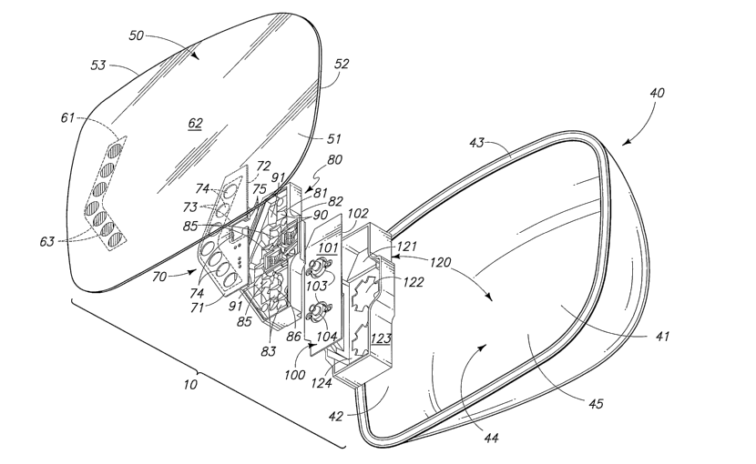
Fig. 1 is a greatly simplified, perspective exploded view of one form of the
electromagnetic radiation assembly of the present invention.
CA 02613267 2007-12-21
WO 2007/001885 5 PCT/US2006/023359
Fig. 2 is a partial, plan view of the electromagnetic radiation assembly of
the
present invention with a semitransparent substrate thereof removed to show the
structure thereunder.
Fig. 3 is a transverse, vertical, sectional view of the electromagnetic
radiation
assembly of the present invention and which is taken from a position along
line 3-3 of
Fig. 2.
Fig. 4 is a longitudinal, vertical, sectional view of the electromagnetic
radiation
assembly of the present invention and which is taken from a position along
line 4-4 of
Fig. 2.
Fig. 5 is a perspective transverse, vertical, sectional view of the
electromagnetic
radiation assembly of the present invention and which is again taken from a
position
along line 3-3 of Fig. 2.
Fig. 6 is a partial, plan view of a second form of the electromagnetic
radiation
assembly of the present invention.
Fig. 7 is a greatly simplified, perspective, exploded view of the second form
of the
electromagnetic radiation assembly of the present invention.
Fig. 8A, B and C are greatly simplified, schematic views of the pattern of
visibly
discernable electromagnetic radiation emitted by the first and second forms of
the
invention during their various modes of operation.
DETAILED DESCRIPTION OF THE PREFERRED EMBODIMENTS
Referring more particularly to the drawings, the electromagnetic radiation
assembly of the present invention is generally indicated by the numeral 10 in
Fig. 1 and
following. For illustrative convenience the electromagnetic radiation assembly
10 of the
present invention, and which is shown and described herein, is discussed as it
would be
configured if it were installed on an overland vehicle 11 of conventional
design and which
is best seen by reference to Fig. 8. As discussed in many of the earlier prior
art patents,
the electromagnetic radiation assembly (hereinafter referred to as assembly
10) of the
present invention operates as a combination rearview mirror, and visual
signaling device,
and wherein the visual signaling device provides a visual signal or pattern of
illumination
which is capable of being perceived from various locations which are located
in assorted
different directions which are laterally outwardly, inwardly, and rearwardly
of the overland
vehicle, when the invention is operating in its several operational modes. As
will be
discussed in greater detail hereinafter, the present assembly 10 is operable
to generate
visibly discernable electromagnetic radiation which can be seen as illustrated
in Fig. 8A
at locations laterally outwardly relative to the overland vehicle 11;
laterally inwardly
CA 02613267 2007-12-21
WO 2007/001885 6 PCT/US2006/023359
relative to the overland vehicle as seen in Fig. 8B; and rearwardly and
downwardly as
seen in Fig. 8C. Other emission patterns are also possible. These various
modes of
operation of the assembly 10 will be discussed in greater detail hereinafter.
As seen in Fig. 8, the present invention 10 is mounted on an overland vehicle
11
of conventional design. The overland vehicle 11 has a front or forward portion
12, and a
rearward portion 13. The overland vehicle 11 further has a passenger
compartment 14
where an operator of the overland vehicle is seated. Still further, the
overland vehicle
includes exterior locations 21 for a pair of exterior rearview mirrors which
incorporate the
present invention and which are best understood by a study of Fig. 1 and 7,
respectively.
These forms of the invention will be discussed in greater detail below. As
should be
understood, the overland vehicle 11 also has a hand operated directional
signaling
switch; and foot brake (not shown), and which when utilized, provides an
electrical signal
which may alert drivers of other vehicles in the immediate vicinity that the
overland
vehicle 11 is about to change directions, turn, change lanes, etc. Yet
further, other
signals or warning icons may also be provided, and which can be viewed from
the
overland vehicle and which will alert the operator of various conditions
existing on the
overland vehicle, or outside ambient environmental conditions which may effect
the safe
operation of the overland vehicle. In addition to the foregoing, the overland
vehicle 11
may be equipped with a radio frequency receiver 22 and which receives an RF
signal
which is transmitted from a key fob held by the operator of the overland
vehicle (not
shown). This RF signal, once received, is effective to unlock the various
doors of the
overland vehicle and further is useful in actuating the operation of the
assembly 10 in
one of its several modes of operation, as will be discussed below.
As best illustrated in Fig. 8, an operator of an overland vehicle 11 when
positioned in the operator's position 20 has a field of view which extends
approximately
180 from the operator's position towards the forward portion 12 of the
vehicle. Further,
and by using a pair of the assemblies 10 which are individually located at the
positions
21 on the exterior portion of the overland vehicle 11, the operator may, by
looking along
given lines of sight, view rearwardly of the vehicle along the driver's side,
passenger
side, and substantially along a longitudinal axis 23 of the overland vehicle
11 when the
operator views an interior rearview mirror, which is not shown. As depicted in
Figs. 8A,
B and C, the assembly 10 of the present invention, when energized, provides a
plurality
of illumination zones which are generally indicated by the numeral 30. These
illumination zones include a first illumination zone 31 (Fig. 8A) which
provides visibly
discernable electromagnetic radiation which is visible at positions which are
laterally,
outwardly relative to the intended direction of travel of the overland vehicle
11. This first
CA 02613267 2007-12-21
WO 2007/001885 7 PCT/US2006/023359
illumination zone is designed to direct visibly discernable electromagnetic
radiation at
vehicles traveling rearwardly and in adjacent lanes relative to the overland
vehicle 11
when the apparatus is operating in a first mode. Still further, the second
illumination
zone 32 provides visibly discernable electromagnetic radiation which is
oriented
substantially laterally, inwardly relative to the direction of movement of the
overland
vehicle, and which can be perceived by the operator of same when the apparatus
is
operating in a second mode. Typically, this second illumination zone is
employed to
transmit information of interest to the operator of the overland vehicle 11
regarding the
operational conditions of the overland vehicle 11 as well as other information
which may
be of interest in the safe operation of the overland vehicle 11. Still
further, the assembly
10, when energized, provides a third illumination zone 33 which is oriented
substantially
laterally inwardly, and downwardly towards the face of the earth when the
apparatus is
operating in a third mode. The third illumination zone is utilized typically
for purposes of
illuminating the side and region adjacent to the overland vehicle during
periods of
reduced visibility in order for an operator to safely enter or exit the
overland vehicle.
These various illumination zones will be discussed in greater detail
hereinafter.
Referring now to Fig. 1, the first form of the assembly 10 of the present
invention
is incorporated into a mirror housing which is generally indicated by the
numeral 40, and
which is typically mounted at the mirror locations 21 on the exterior surface
of the
overland vehicle 11. The mirror housing or enclosure has a rear wall 41, and a
sidewall
42 extends outwardly therefrom. The sidewall 42 has a peripheral edge 43 and
which
defines an aperture 44 having given dimensions. The rear wall 41, and sidewall
42
further defines a cavity 45 which receives and encloses the assembly 10, and
other
associated devices such as a movable bezel, which is not shown. As should be
understood, the bezel may also include a cavity which matingly receives, at
least in part,
the assembly 10. The bezel movably supports the assembly 10 within the housing
40.
The assembly 10 can be positionally adjusted either manually, or remotely, by
an
actuator (not shown) to a given angular orientation relative to the various
lines of sight
utilized by the operator (not shown) of the overland vehicle 11. This movement
of the
assembly provides a means by which the operator may adjust his given field of
view
rearwardly of the overland vehicle 11.
The assembly 10 of the present invention, as seen in Fig. 1 and following,
includes a semitransparent substrate which is generally indicated by the
numeral 50, and
which has a front, first or outside facing surface 51, and an opposite, second
or
rearwardly facing surface 52. In automotive applications, the semitransparent
substrate
is a semitransparent mirror which is selected from the group of
semitransparent mirrors
CA 02613267 2007-12-21
WO 2007/001885 8 PCT/US2006/023359
comprising substantially neutrally chromatic; dichroic; electrochromic and/or
combinations thereof. The semitransparent substrate or mirror 50 further is
defined by a
peripheral edge 53, which substantially corresponds in shape and in size to
the aperture
44 which is defined by the peripheral edge 43 of the housing 40. When
assembled, the
semitransparent mirror or substrate 50 substantially occludes the aperture 44.
The
semitransparent substrate or mirror 50 of the present invention may take on
several
forms. As seen in Figs. 1 and 7, the semitransparent substrate or mirror
typically
comprises a substantially transparent or translucent substrate which has a
highly
reflective coating applied thereto. As should be understood, the reflective
coating may
be applied, either, on the one hand, to the first or outside facing surface
51, or in the
alternative, and more typically to the opposite, second or rearwardly facing
surface 52.
The highly reflective coating may comprise any number of different highly
reflective or
mirror like coatings or substances such as chromium and the like, and which
may be
applied or formed in a manner which provides a commercially acceptable
reflective
surface. Still further, other coatings may be applied, for example, to the
opposite
rearwardly facing surface 52 such as masking layers and the like and which
render the
semitransparent substrate or mirror substantially opaque. For automotive
applications,
the resulting reflectance of the semitransparent mirror or substrate 50 should
be
generally, on average, greater than about 35%. However, in other commercial
applications, increased or decreased reflectance may be acceptable depending
upon the
end use of the assembly 10.
As best seen in Figs. 1 and 7, for example, the semitransparent substrate or
mirror 50 has a first, or primary region 61, and through which a visibly
discernable
electromagnetic radiation signal may pass; and an adjacent secondary region
62. While
only two regions are shown and discussed herein, it is of course possible to
have a
plurality of secondary regions depending upon the end use of the assembly 10.
These
secondary regions may be adjacent to each other, or may be spaced at a
distance and
positioned at various locations about the semitransparent substrate or mirror
50. As a
general matter, however, the first or primary region 61 passes a portion of
the visibly
discernable electromagnetic radiation directed at same while simultaneously
reflecting a
given percentage of the visibly discernable electromagnetic radiation or light
which
comes from the ambient environment. On the other hand, the secondary region 62
is
operable to reflect ambient visibly discernable electromagnetic radiation and
is otherwise
considered nominally opaque. Depending upon the reflective or other masking
layers
which are applied to the opposite, rearwardly facing surface 52, the secondary
region 62
may be considered completely opaque. As discussed above, the combined average
CA 02613267 2007-12-21
WO 2007/001885 9 PCT/US2006/023359
reflectance of the overall surface area of the semitransparent substrate or
mirror 50,
including both the primary and secondary regions, is typically greater than
about 35%
when the assembly 10 is being employed for automotive applications, as noted
above.
In other industrial applications, the average reflectance may be lower or
higher
depending upon the desired end use. As seen in the drawings, the secondary
region 62
is substantially continuous and reflects for automotive applications greater
than about
35% of the ambient, visible, electromagnetic radiation, and which strikes the
first outside
facing surface 51 thereof. Typically, in most automotive applications, the
secondary
region 62, on average, passes less than about 10% of the ambient visibly
discernable
electromagnetic radiation. The first or primary region 61, on the other hand,
passes less
than about 50% of visible electromagnetic radiation, and further reflects on
average, less
than about 40% of visible electromagnetic radiation. The ranges noted above
have been
found suitable for automotive applications, however, it will be recognized
that other
broadened or narrowed ranges may be useful for other industrial applications.
As seen in Fig. 1, the semitransparent mirror 50 includes a plurality of
discrete
apertures or regions 63 which may be formed in a given pattern, and in various
densities
in the reflective coating, and which facilitates the passage of visibly
discernable
electromagnetic radiation therethrough. With respect to the semitransparent
mirror or
substrate 50, the first or primary region 61 may be formed by a number of
different
means including providing reduced thickness areas in the associated reflective
coating
which is provided. These reduced thickness areas in the mirror coating allow
increased
amounts of visibly discernable electromagnetic radiation to pass therethrough
in relative
comparison to the adjacent thicker areas in the secondary region 62. Further,
the
secondary region, as earlier discussed, may be coated with an opaque masking
layer
which substantially inhibits visibly discernable electromagnetic radiation
from passing
therethrough. Still further, the semitransparent mirror or substrate 50 may
have a
dichroic mirror coating applied thereto. The usefulness of dichroic mirror
coatings of
various types have been discussed in various U.S. Patents including U.S.
Patent No.
5,014,167 and 5,207,492 to name but a few. These dichroic mirror coatings are
well
known in the art, and further discussion regarding the nature and operation of
these
respective mirror coatings is not warranted. In connection with such dichroic
mirror
coatings, a substantially opaque masking layer, as earlier discussed, may be
applied
over the secondary region 62 thereby making the secondary region substantially
opaque
and further permitting visible electromagnetic radiation to pass through the
first or
primary region 61 which is unmasked. As discussed in the earlier prior art
patents, the
dichroic mirror coating which is applied to the semitransparent mirror or
substrate 50
CA 02613267 2007-12-21
WO 2007/001885 10 PCT/US2006/023359
may be selected to pass given bands of visibly discernable electromagnetic
radiation or
light in greater amounts than other bands of electromagnetic radiation thereby
making
the resulting semitransparent mirror or substrate 50, on average, an
acceptable reflector
of visibly discernable electromagnetic radiation while simultaneously allowing
increased
amounts of visibly discernable electromagnetic radiation of the selected band
of
electromagnetic radiation to pass therethrough. In addition to the foregoing,
another
acceptable semitransparent mirror or substrate 50 may include an
electrochromic mirror
of a construction similar to that seen in U.S. Patents No. 6,257,746; and
6,512,624 the
teachings of which are incorporated by reference herein. In view of these
teachings, an
electrochromic mirror may be useful in the practice of the present invention
10 as will be
discussed in greater detail below. It is also possible to provide combined
substrates 50
depending upon the end use of the assembly.
Referring now to Figs. 1, and following, the assembly 10 of the present
invention
includes a first substantially opaque substrate which is generally indicated
by the
numeral 70. The first opaque substrate operates, at least in part, as a
circuit board in
order to mount a plurality of electromagnetic radiation emitters which will be
discussed
below. The first substrate 70 has a first surface 71, which is typically
juxtaposed relative
to the second or rearwardly facing surface 52 of the semitransparent mirror
50. The first
substrate 70 has a distinct second surface 72. Still further, the first
substrate 70 defines,
at least in part, one region 73 (Fig. 1), although a plurality of regions may
be defined, and
through which visibly discernable electromagnetic radiation may pass. As seen,
the
region through which the electromagnetic radiation may pass 73 may include a
plurality
of apertures 74 which are formed in the first substrate 70 and which extend
therethrough.
The apertures 74 are positioned in a predetermined pattern in order to provide
a
resulting visual signal which may be viewed and understood by others at a
distance
relative to the overland vehicle 11. As seen in Figs. 1 and 2, the first
substantially
opaque substrate 70 mounts on the second surface 72 thereof, a first plurality
of
electromagnetic radiation emitters 75. The second surface 72 also mounts
electrically
conductive passageways (not shown), and which electrically couple the
respective
electromagnetic radiation emitters 75 with a source of electrical power which
is typically
provided by the overland vehicle 11. As should be understood, the first
plurality of
electromagnetic radiation emitters 75, when energized, emit visibly
discernable
electromagnetic radiation which travels along a path which is generally
indicated by the
numeral 76 (Figs. 3 and 5), and which forms the first illumination zone 31, as
seen in Fig.
8A. As seen in Fig. 1, it will be understood that the first plurality of
electromagnetic
radiation emitters are mounted on the second surface 72 of the first opaque
substrate
CA 02613267 2007-12-21
WO 2007/001885 11 PCT/US2006/023359
70, and near the region 73 which passes the visibly discernable
electromagnetic
radiation. As illustrated in Fig. 1, the individual electromagnetic radiation
emitters are
typically associated with the individual apertures 74 which are formed in the
first opaque
substrate 70. While the discussion above was directed to visibly discernable
electromagnetic radiation, it is possible by means of the present invention to
emit
electromagnetic radiation which is not visible and which would be useful in
other
applications.
Referring now to Figs. 1, 3 and 4, it will be seen that the assembly 10 of the
present invention includes a reflector which is generally indicated by the
numeral 80.
The reflector can be fabricated by utilizing standard injection molding
techniques, and
post, reflective coating procedures. Alternatively, it may be pressure or
vacuum formed
from deformable sheets that have a highly reflective coating formed thereon.
The
reflector 80 has a first surface 81 which is positioned near the second
surface 72 of the
first opaque substrate 70; and a distinct second surface 82, as best seen by
reference to
Fig. 3. In the arrangement as shown in Fig. 4, it will be seen that the first
opaque
substrate 70 matingly cooperates with the reflector 80 such that the reflector
80 is
juxtaposed, at least in part, relative to the semitransparent mirror or
substrate 50. As
seen by reference to Fig. 4, it will be understood that the first plurality of
electromagnetic
radiation emitters 75 are positioned near, but in spaced relation relative to,
the first
surface 81 of the reflector 80. As best understood by a study of Fig. 1 and 3,
respectively, the reflector 80 includes a first portion 83, and a second
portion 84. The
first portion 83 of the reflector 80 includes a plurality of individual
reflector pockets 85
which define cavities 86. The individual reflector pockets 85 are typically
positioned in
substantially eccentric reflecting relation relative to the first plurality of
electromagnetic
radiation emifters 75. When energized, the respective reflector pockets
individually
reflect the visibly discernable electromagnetic radiation 76 emitted by the
first plurality of
electromagnetic radiation emitters 75 in a first direction, as illustrated,
and into the
illumination zone 31 as seen in Fig. 8A. As illustrated in the drawings, the
respective
reflector pockets 85 typically include multiple reflector facets which are
generally
indicated by the numeral 90. The respective reflector facets are operable to
reflect the
emitted visibly discernable electromagnetic radiation into the illumination
zones as
illustrated in Figs. 8A-C, respectively during the various modes of operation
of the
invention. With respect to the second portion 84 of the reflector 80, it
should be
understood that the second portion 84 of the reflector 80 comprises, at least
in part, an
aperture 91 which extends through the reflector and which allows visibly
discernable
electromagnetic radiation generated by a second electromagnetic radiation
emitter,
CA 02613267 2007-12-21
WO 2007/001885 12 PCT/US2006/023359
which will be discussed below, to pass therethrough. The second portion 84 of
the
reflector further includes a reflector facet 92 having a reflecting surface 93
(Fig. 5) which
is located adjacent to the aperture 91 and which is further positioned in
spaced relation
relative to the second surface 82 of the reflector 80 (Fig. 4), and oriented
in reflecting
relation relative to the second electromagnetic radiation emitter as will be
described
hereinafter. In the arrangement as seen in Fig. 3, it will be understood that
visibly
discernable electromagnetic radiation emitted by the second electromagnetic
radiation
emitter is reflected by the reflector facet 92 of the second portion 84, and
in a second
direction where it passes into the illumination zone 33 as seen in Fig. 8C. As
should be
noted, the visibly discernable electromagnetic radiation from both emitters is
passed by
the first region 61 of the semitransparent substrate 50, and viewed at
locations forward
of the first surface of the first substrate 70.
Referring now to Figs. 1, 3, 4 and 5, it will be seen that the assembly 10
includes
a second supporting substrate 100, and which is located in spaced relation
relative to the
first substantially opaque substrate 70. As illustrated, the reflector 80 is
positioned
therebetween the first and second substrates 70 and 100, respectively. As seen
in the
drawings, the second supporting substrate has a first surface 101 which rests,
at least in
part, in contact with the second surface 82 of the reflector 80, and a second
surface 102.
Still further, a plurality of apertures 103, as seen in Fig. 4, are formed in
the second
supporting substrate 100. Matingly received within, and disposed in an
occluding
relation relative to the apertures 103, are individual, second electromagnetic
radiation
emitters 104, here illustrated as side emitting, light emitting diodes. As
depicted in Fig.
4, it should be understood that each of the second plurality of
electromagnetic radiation
emitters, here illustrated as side emitting, light emitting diodes 104,
include a heat sink
105. As should be understood, during operation, and when energized, the second
plurality of electromagnetic radiation emitters 104 generate heat energy. The
arrangement, as shown in Fig. 4, allows the heat energy generated by the
second
plurality of electromagnetic radiation emitters 104 to be dissipated, at least
in part, into
the housing 40 and thereby prevent the undue buildup of heat energy in the
assembly 10
which may cause a failure of the assembly 10 and/or the individual
electromagnetic
radiation emitters 104, as provided. When energized, the second plurality of
electromagnetic radiation emitters 104 emits visibly discernable
electromagnetic
radiation 106 which is reflected by the second portion 84 of the reflector 80
along a
course of travel to form the illumination zone 33 as seen in Fig. 8C. A
portion of this
second course of travel is in a different direction from that provided by the
first
electromagnetic radiation emitters 75. As best understood by a study of Fig.
1, 2, and 4,
CA 02613267 2007-12-21
WO 2007/001885 13 PCT/US2006/023359
the assembly 10 may include a third plurality of electromagnetic radiation
emitters which
are generally indicated by the numeral 110. This third plurality of
electromagnetic
radiation emitters 110 are mounted on the second surface 72 of the first
substrate 70,
and are electrically coupled to suitable electrical pathways which are borne
by the
second surface of the first substrate (not shown). As seen most clearly by
reference to
Figs. 3 and 4, the third plurality of electromagnetic radiation emitters 110
are each
individually associated with respective reflector pockets 85 and which are
formed and
otherwise oriented in a fashion so as to project the electromagnetic radiation
111 emitted
by the third plurality of electromagnetic radiation into the illumination zone
32 as seen in
Fig. 8B and in a third direction.
Referring now to Fig. 1 and following, it will be seen that the assembly 10
includes a housing which is generally indicated by the numeral 120. The
housing is
operable to receive, and partially enclose, in a somewhat nested arrangement,
the
various assemblies, discussed above. In this regard, the housing 120 includes
a bottom
portion 121. The bottom portion 121 includes a plurality of apertures 122,
which are
substantially coaxially aligned relative to the heat sinks 105 of the
respective second
plurality of electromagnetic radiation emitters 104. The apertures 122 further
facilitates
the dissipation of the heat energy generated during the energizing of the
respective
second electromagnetic radiation emitters into the housing 40, and which is
mounted on
the overland vehicle 11. Extending generally normally upwardly relative to the
bottom
portion 121 is a substantially continuous sidewall 123. The sidewall and
bottom portion
121 define a cavity 124 which matingly and nestingly receives and otherwise
operably
cooperates with the assemblies described above. The housing 120 is itself,
then
matingly or otherwise mounted, along with the semitransparent mirror or
substrate 50, to
a mirror bezel (not shown) and which is received within the housing 40. In
this fashion,
the assembly 10 can be oriented in a proper position so as to be useful to the
operator of
an overland vehicle 11.
Referring now to Fig. 7, a second form of the invention is generally indicated
by
the numeral 130. As shown therein, the second form of the invention includes
many
features similar to that of the first form of the invention 10. Like
structures in many
instances have been shown and for those reasons bear similar numbers. In this
regard,
the semitransparent mirror or substrate 50, second substrate 100, and housing
120 are
substantially identical to that described with respect to the first form of
the invention, and
therefore further discussion with respect to those structures is not
warranted. The
second form includes a first substrate 131 which has a different shape from
that seen
with respect to the first form as illustrated in Fig. 1. The first substrate
131 has a first
CA 02613267 2007-12-21
WO 2007/001885 14 PCT/US2006/023359
surface 132, and a second surface 133. As seen, a first plurality of
electromagnetic
radiation emitters 134 are mounted on the second surface 133. Suitable
electrical
conduits are borne by the second surface and are coupled to a source of
electricity
which is typically supplied by the automotive platform 11. As should be
understood by a
study of Fig. 6, the first substrate, and housing 120, in combination and in
the assembled
form as seen in Fig. 6 defines discrete regions 135 through which emitted
electromagnetic radiation, as described below, passes. This electromagnetic
radiation is
then passed by the semitransparent mirror or substrate 50 such that it forms a
discrete
signal which can be viewed at a distance from the assembly 130. As should be
understood, and when assembled, the first surface 132 would be juxtaposed
relative to
the second surface 52 of the semitransparent substrate 50, and in the region
61.
As seen in Fig. 7, the second form of the invention 130 includes a reflector
140
which has a first surface 141, and a discrete, second surface 142. Still
further, the
reflector has a first portion 143 and a second portion 144. As seen in Fig. 7,
the first
portion 143 is defined by a plurality of individually discrete reflector
pockets 150 which
are somewhat similar in their overall function as that seen in the earlier
form of the
invention 10. In this regard, the plurality of reflector pockets 150 are
defined by
individual reflector facets 151 (Fig. 6), and are operable, as seen, to
reflect the
electromagnetic radiation 152 in various directions. As seen in Fig. 6, some
of the
plurality of reflector pockets 150 reflect the emitted electromagnetic
radiation 152 in a
first direction so as to be seen within the illumination zone 31 as seen in
Fig. 8A.
Further, the second portion 144 of the reflector 140 is defined, at least in
part, by
individual apertures 160 which are formed in the reflector 140. Still further,
the second
portion 144 includes individual reflector facets 161 which extend away from
the first
surface 141 and are positioned in reflecting relation relative to the second
electromagnetic radiation emitters 104 and which are mounted on the second
substrate
100. When energized, the electromagnetic radiation of the second plurality of
electromagnetic radiation emitters 104 is reflected in a second direction as
indicated by
the line labeled 162. This electromagnetic radiation is then provided to the
illumination
zone 33 as seen in Fig. 8C.
In the second form of the invention 130, a third plurality of electromagnetic
radiation emitters 170 is provided and which are mounted on the second surface
133 of
the first substrate 131. When energized, the third plurality of
electromagnetic radiation
emitters are operable to provide electromagnetic radiation 171 which is
reflected by
individual reflector pockets 150 into the illumination zone 32 as seen in Fig.
8B. As seen
in Fig. 6, where the second form of the invention 130 is shown in an assembled
CA 02613267 2007-12-21
WO 2007/001885 15 PCT/US2006/023359
configuration, this assembled configuration is then received or otherwise
mounted on a
mirror bezel, (not shown), along with the semitransparent mirror or substrate
50 and
thereafter oriented in an appropriate fashion so as to be useful to an
operator of an
overland vehicle 11.
OPERATION
The operation of the described embodiment of the present invention is believed
to be readily apparent and is briefly summarized at this point.
Referring now to Figs. 1 and following, an electromagnetic radiation assembly
10
and 130 of the present invention includes a reflector 10 and 140 which has
first and
second surfaces 81, 82, 141, 142, and first and second portions 83, 84, 143,
144.
Further, this assembly 10, 130 further includes a first electromagnetic
radiation emitter
75, 134 positioned adjacent to the first surface, and which, when energized,
emits visibly
discernible electromagnetic radiation 76, 152 which is reflected by the first
portion of the
reflector so as to be visible at locations forward of the first surface; and a
second
electromagnetic radiation emitter 104, positioned adjacent to the second
surface of the
reflector, and which, when energized, emits visibly discernible
electromagnetic radiation
162 which is reflected by the second portion of the reflector so as to be
visible at
locations forward of the first surface. The electromagnetic radiation assembly
10 of the
present invention further includes a semitransparent mirror or substrate 50.
The visibly
discernable electromagnetic radiation emitted by the first and second
electromagnetic
radiation emitters 75, 104, 134 passes through the semitransparent mirror and
can be
seen at a distance, and in different directions, and typically within the
illumination zones
31, 32 and 33, respectively.
With regards to the electromagnetic radiation assembly 10, the present
invention
includes a first substantially opaque substrate 70 positioned therebetween the
semitransparent mirror or substrate 50 and the reflector 80. The first opaque
substrate
defines a region 73 through which the visibly discernable electromagnetic
radiation may
pass. With regard to the first and second forms of the invention 10 and 130,
the first
electromagnetic radiation emitter 75, 134 is mounted on the first opaque
substrate 70,
131 and near the region which passes the visibly discernable electromagnetic
radiation.
The electromagnetic radiation assembly 10 and 130 of the present invention
further
includes a second substrate 100 which is positioned in spaced relation
relative to the
second surface 82, 142 of the reflector 80, 140. In this regard, the reflector
is located
therebetween the first substrate 70, 131 and the second substrate 100, and the
second
electromagnetic radiation assembly 104 is mounted on the second substrate 100.
With
CA 02613267 2007-12-21
WO 2007/001885 PCT/US2006/023359
16
regards to the first and second forms of the invention, the first portion 83,
143 of the
reflector 80, 140 comprises, at least in part, a reflector pocket 85, 150
having multiple
reflector facets. The respective reflective pockets each define a cavity 86
which is
typically positioned in eccentric, reflecting relation relative to the first
electromagnetic
radiation emitters 75, 134. The respective reflector pockets reflects the
emitted visibly
discernable electromagnetic radiation emitted by the first electromagnetic
radiation
emitter 75, 134 in a first direction as illustrated in the drawings. In the
arrangement as
seen, the second portion 84 of the reflector 80, 140 comprise, at least in
part, an
aperture 91, 160 which allows the visibly discernable electromagnetic
radiation
generated by the second electromagnetic radiation emitter 104 to pass
therethrough.
The second portion includes a reflector facet 92, 161 having a reflecting
surface which is
located adjacent to the aperture and which is further positioned in spaced
relation
relative to the second surface 82, 142 of the reflector 80, 140, and in
reflecting relation
relative to the second electromagnetic radiation emitter 104. Visibly
discernable
electromagnetic radiation emitted by the second electromagnetic radiation
emitter 104 is
reflected by the reflector facet of the second portion of the reflector in the
second
direction. In the arrangement as seen, a third electromagnetic radiation
emitter 110, 170
is mounted on the second surface 72, 133 of the first substrate 70, 100, and
wherein the
electromagnetic radiation generated by the third electromagnetic radiation
emitter is
reflected by one of the reflector facets in a third direction. When assembled,
and as
seen in the drawings, the emitted visibly discernable electromagnetic
radiation is
operable to pass through the semitransparent substrate or mirror 50, and pass
into first,
second and third illumination zones 31, 32, and 33, respectively so as to be
useful to the
operator of the overland vehicle 11, or other vehicles traveling adjacent
thereto.
Therefore, it will be seen that the electromagnetic radiation assembly 10, 130
of
the present invention provides many advantages over the prior art devices
which have
been utilized heretofore. As will be recognized, the present assembly 10 and
130 is
compact, cost efficient, and further provides a convenient means whereby
discernable
electromagnetic radiation may be projected in various directions and patterns
relative to
the overland vehicle to assist the operator in the use of the overland
vehicle.