Note: Descriptions are shown in the official language in which they were submitted.
CA 02613524 2007-12-27
WO 2007/002992
PCT/AU2006/000923
- 1 -
PULMONARY MONITORING SYSTEM
Background of the Invention
The present invention relates to a method and apparatus for monitoring
biological parameters, and in
particular to a method and apparatus for performing impedance measurements to
determine the
presence, absence or degree of pulmonary oedema.
Description of the Prior Art
The reference in this specification to any prior publication (or information
derived from it), or to any
matter which is known, is not, and should not be taken as an acknowledgment or
admission or any
form of suggestion that the prior publication (or information derived from it)
or known matter forms
part of the common general knowledge in the field of endeavour to which this
specification relates.
The clinical management of heart failure consumes approximately 1% to 2% of
the health care budget
in developed countries, with the majority of this expense due to costs
associated with hospitalisation.
A pan-European survey has shown that up to 65% of patients who are
hospitalised for clinical heart
failure have had previous admissions for such a condition. Typically admission
for clinical heart
failure lasts for an average of 11 days with a risk of re-hospitalisation of
24%.
One of the major risks associated with congestive heart failure is the
development of pulmonary
oedema, which is caused by the extravascular accumulation of fluid in the
pulmonary tissue and air
spaces. Whilst this is a serious problem, and can have fatal consequences if
not correctly treated,
treatment is relatively straightforward and typically involves the use of
diuretics to reduce fluid levels.
However, assessment and monitoring of pulmonary oedema is a complex process.
In particular
current techniques typically involve ionising radiation or invasive methods,
and accordingly, such
processes can only be performed under adequate medical supervision. For home
monitoring of
pulmonary oedema or the extent of congestive heart failure (CHF), the current
clinically accepted
methodology is for the patient to weigh themselves in the morning following
their morning
absolutions. If their weight has changed by a significant factor since their
last measurement they are
advised to call their physician. Physicians rely on subjective assessment of
exercise tolerance and
breathlessness, changes in body weight and clinical examination to detect
increasing dependent
oedema or lung crackles.
Other methods have been proposed for the accurate measurement of assessing
heart failure ranging
from the use of implantable devices for hemodynamic monitoring, implantable
intra-thoracic
CA 02613524 2007-12-27
WO 2007/002992 PCT/AU2006/000923
- 2 -
impedance monitors and serial measurements of B-type natriuretic peptide.
Implantable devices are
not suitable for the general population and have all the associated risk
factors that arise from such
systems, whilst B-type natriuretic peptide monitoring is restricted to major
health care centres and is
not practical for home monitoring.
Accordingly, in many cases, onset or progression of pulmonary oedema is not
detected until the
patient is admitted to hospital. The patient is then often required to remain
in hospital whilst
treatment is provided, to allow adequate monitoring of the patient's recovery.
However, if adequate
diagnosis and monitoring techniques were available many of such hospital
visits could be avoided
thereby vastly reducing the burden on the health care system.
One existing technique for determining biological parameters relating to a
subject involves the use of
bioelectrical impedance. This involves measuring the electrical impedance of a
subject's body using
a series of electrodes placed on the skin surface. Changes in electrical
impedance at the body's
surface are used to determine parameters, such as changes in fluid levels.
A complication in such techniques is that the baseline impedance of the thorax
varies considerably
between individuals, the quoted range for an adult is 20 f2 - 48 n at a
frequency between 50 kHz -
100 kHz, and variations in impedance due to changes in fluid level can be
quite small. This leads to a
very fragile signal with a low signal to noise ratio. As a result these
techniques have not been suitable
for monitoring pulmonary oedema, other than through invasive techniques, which
as discussed above
do not provide a suitable mechanism for monitoring patients in most cases.
Summary of the Present Invention
In a first broad form the present invention provides a method of monitoring
pulmonary oedema in a
subject, the method including, in a processing system:
a) determining a measured impedance value for at least two body segments, at
least one of the
body segments being a thoracic cavity segment;
b) for each body segment, and using the measured impedance values, determining
an index; and,
c) determining the presence, absence or degree of pulmonary oedema using the
determined
indices.
Typically the index is of a ratio of the extra-cellular to intra-cellular
fluid.
Typically the method includes, in the processing system:
a) comparing the indices of the body segments; and,
CA 02613524 2007-12-27
WO 2007/002992
PCT/AU2006/000923
- 3 -
b) determining the presence, absence or degree of pulmonary oedema using the
results of the
comparison.
Typically the method includes, in the processing system:
a) determining an index ratio based on a ratio of the indices;
b) comparing the index ratio to at least one reference; and,
c) determining the presence, absence or degree of pulmonary oedema using the
results of the
comparison.
Typically the reference includes at least one of:
a) a predetermined threshold;
b) a tolerance determined from a normal population; and,
c) a predetermined range.
Typically the reference includes an index ratio previously determined for the
subject.
Typically the method includes, in the processing system:
a) determining a plurality of measured impedance values for each body
segment, each measured
impedance value being measured at a corresponding measurement frequency; and,
b) determining the index ratio based on the plurality of measured impedance
values.
Typically the method includes, in the processing system, and for each body
segment:
a) determining values for parameters R0 and Roo from the measured impedance
values; and,
b) calculating the index (/) using the equation:
R.
I = _____
Ro ¨
where:
Ro is the resistance at zero frequency; and,
Ro, is the resistance at infinite frequency.
Typically the method includes, in the processing system, determining the
parameter values using the
equation:
Ro ¨ R.
Z = R.+ 1+ (i cor)(1-.)
where:
Z is the measured impedance at angular frequency co,
is a time constant, and
CA 02613524 2007-12-27
WO 2007/002992 PCT/AU2006/000923
- 4 -
a has a value between 0 and 1.
Typically the method includes, in the processing system:
a) determining the impedance of each body segment at four discrete
frequencies; and,
b) determining values for the parameters by solving the equation using four
simultaneous
equations.
Typically the method includes, in the processing system, determining the
parameter values by:
a) determining an impedance locus using the measured impedance values; and,
b) using the impedance locus to determine the parameter values.
Typically the thoracic cavity segment corresponds to the entire thoracic
cavity.
Typically wherein the other body segment is at least one other thoracic cavity
segment.
Typically the at least one other body segment is a limb.
Typically the method includes, in the processing system, determining if the at
least one other body
segment suffers from oedema.
Typically the method includes, in the processing system:
a) determining, using measured impedance values, the impedance of the entire
subject and each
limb; and,
b) subtracting the limb impedance values from the entire subject impedance
values to determine
the impedance of the thoracic cavity.
Typically the method includes, in the processing system:
a) causing one or more electrical signals to be applied to the subject using a
first set of
electrodes, the one or more electrical signals having a plurality of
frequencies;
b) determining an indication of electrical signals measured across a second
set of electrodes
applied to the subject in response to the applied one or more signals;
c) determining from the indication and the one or more applied signals, an
instantaneous
impedance value at each of the plurality of frequencies; and,
d) determining the index using the instantaneous impedance values.
Typically a number of electrodes are provided on the subject's thoracic
cavity, and wherein the
method includes, in the processing system:
a) causing one or more electrical signals to be applied to a pair of
the electrodes;
b) determining an indication of electrical signals measured across each other
pair of electrodes;
CA 02613524 2007-12-27
WO 2007/002992 PCT/AU2006/000923
-5 -
c) determining from the indication and the one or more applied signals, an
instantaneous
impedance value for at least one thoracic cavity segment; and,
d) repeating steps a) to c) by applying electrical signals to each other pair
of the electrodes to
thereby determine impedance values for a number of thoracic cavity segments.
Typically the method includes, in the processing system:
a) determining at least one impedance measurement to be performed;
b) determining at least one electrode arrangement associated with the
determined impedance
measurement;
c) displaying a representation indicative of the electrode arrangement;
and,
d) causing the impedance measurement to be performed once the electrodes have
been provided
in accordance with the displayed representation.
Typically the method includes, in the computer system, displaying an
indication of at least one of:
a) the parameter values;
b) the ratio of extra-cellular to intra-cellular fluid; and,
c) an indication of the at least one of the presence, absence or degree of
tissue oedema in the
subject.
Typically the method includes, in the processing system:
a) determining an electrode identifier associated with at least one electrode
provided on the
subject;
b) determining, using the electrode identifier, an electrode position
indicative of the position of
the at least one electrode on the subject; and,
c) performing at least one impedance measurement using the electrode position.
Typically the method includes, in the processing system:
a) determining a parameter associated with at least one electrode lead; and,
b) causing at least one impedance measurement to be performed using the
determined
parameter.
Typically the method includes, in the processing system:
a) receiving configuration data, the configuration data being indicative of
at least one feature;
b) determining, using the configuration data, instructions representing the at
least one feature;
and,
c) causing, using the instructions, at least one of:
i) at least one impedance measurement to be performed; and,
CA 02613524 2007-12-27
WO 2007/002992 PCT/AU2006/000923
- 6 -
ii) at least one impedance measurement to be analysed.
Typically the method includes, in the processing system:
a) causing a first signal to be applied to the subject;
b) determining at least one parameter relating to at least one second signal
measured across the
subject;
c) comparing the at least one parameter to at least one threshold; and,
d) depending on the results of the comparison, selectively repeating steps (a)
to (d) using a first
signal having an increased magnitude.
In a second broad form the present invention provides apparatus for monitoring
pulmonary oedema in
a subject, the apparatus including a processing system for:
a) determining a measured impedance value for at least two body segments, at
least one of the
body segments being a thoracic cavity segment;
b) for each body segment, and using the measured impedance values, determining
an index; and,
c) determining the presence, absence or degree of pulmonary oedema using the
determined
indices.
Typically the apparatus includes:
a) a current supply for generating an alternating current at each of a
plurality of frequencies;
b) at least two supply electrodes for applying the generated alternating
current to a subject;
c) at least two measurement electrodes for detecting a voltage across the
subject; and,
d) a sensor coupled to the measurement electrodes for determining the voltage,
the sensor being
coupled to the processing system to thereby allow the processing system to
determine the
measured impedances.
Typically the apparatus includes a number of electrodes arranged in a band for
fitting to the subject's
thoracic cavity.
Typically the apparatus includes a multiplexing system for selectively
coupling the current supply and
the sensor to the number of electrodes in a predetermined sequence.
In a third broad form the present invention provides a method of diagnosing a
presence, absence or
degree of pulmonary oedema in a subject, the method including, in a processing
system:
a) determining a measured impedance value for at least two body segments, at
least one of the
body segments being a thoracic cavity segment;
b) for each body segment, and using the measured impedance values, determining
an index; and,
CA 02613524 2007-12-27
WO 2007/002992
PCT/AU2006/000923
- 7 -
c) determining the presence, absence or degree of pulmonary oedema using the
determined
indices.
In a fourth broad form the present invention provides apparatus for connecting
measurement
apparatus to an electrode, the apparatus including:
a) a housing having a connector for coupling the housing to an electrode; and,
b) a circuit mounted in the housing, the circuit being electrically coupled to
the electrode using
the connector, and being coupled to a lead, the circuit being for at least one
of:
i) generating predetermined electrical signals in accordance with
control signals received
from the measurement apparatus;
ii) providing an indication of electrical signals applied to the electrode;
and,
iii) providing an indication of electrical signals measured at the electrode.
Typically the circuit is provided on a circuit board having an electrical
contact, and wherein in use the
connector urges at least part of the electrode into abutment with the
electrical contact.
Typically the connector includes a biased arm.
Typically the circuit includes a buffer circuit for:
a) sensing voltage signals at the electrode;
b) filtering and amplifying the voltage signals; and,
c) transferring the filtered and amplified voltage signals to the measurement
apparatus.
Typically the circuit includes a current source circuit for:
a) receiving one or more control signals;
b) filtering and amplifying the control signals to thereby generate one or
more current signals;
c) applying the current signals to the electrode pad; and,
d) transferring an indication of the applied signals to the measurement
apparatus.
Typically the apparatus further comprises an electrode, the electrode
including:
a) an electrode substrate; and,
b) a conductive material for electrically coupling the electrode to the
subject.
Typically the electrode substrate is electrically conductive, and wherein in
use the connector couples
the circuit to the electrode substrate.
Typically the housing includes curved edges.
Typically the housing is formed from a material that, at least one of:
CA 02613524 2007-12-27
WO 2007/002992 PCT/AU2006/000923
- 8 -
a) has a low coefficient of friction; and,
b) is resilient.
In a fifth broad form the present invention provides a method of performing
impedance measurements
on a subject, the method including, in a processing system:
a) determining an encoded value associated with at least one electrode lead;
and,
b) causing at least one impedance measurement to be performed using the
encoded value.
Typically the encoded value is used for calibration.
Typically the encoded value is determined from a resistance value.
Typically the encoded value is indicative of an identity of the lead.
Typically the method includes, in the processing system, controlling the
current applied to the subject
using the determined encoded value.
Typically the encoded value is a lead identifier, and wherein the method
includes, in the processing
system:
a) determining, using the lead identifier, an impedance measurement procedure;
and,
b) causing the determined impedance measurement procedure to be performed.
Typically the method includes, in the processing system:
a) comparing the determined identity to one or more predetermined identities;
and,
b) determining the impedance of the subject in response to a successful
comparison.
Typically the method includes, in the processing system:
a) determining the lead identifier associated with the at least one electrode
lead;
b) determining, using the lead identifier, a lead usage;
c) comparing the lead usage to a threshold; and,
d) in accordance with the results of the comparison, at least one of:
i) generating an alert;
ii) terminating an impedance measurement procedure; and,
iii) performing an impedance measurement procedure.
Typically the method includes, in the processing system, at least one of:
a) processing electrical signals measured from the subject to thereby
determine one or more
impedance values; and,
b) processing determined impedance values.
CA 02613524 2007-12-27
WO 2007/002992
PCT/AU2006/000923
- 9 -
Typically the encoded value is stored in a store.
In a fifth broad form the present invention provides apparatus for performing
impedance
measurements on a subject, the apparatus including:
a) at least one lead for connecting to electrodes coupled to the subject, the
at least one lead
including an encoded value; and,
b) a processing system coupled to the at least one lead for:
i) determining the encoded value; and,
c) causing at least one impedance measurement to be performed using the
encoded value.
In a sixth broad form the present invention provides a method of performing
impedance
measurements on a subject, the method including, in a processing system:
a) determining an electrode identifier associated with at least one electrode
provided on the
subject;
b) determining, using the electrode identifier, an electrode position
indicative of the position of
the at least one electrode on the subject; and,
c) causing at least one impedance measurement to be performed using the
electrode position.
Typically the impedance measurement is performed using at least four
electrodes, each having a
respective identifier, and wherein the method includes, in the processing
system:
a) determining an electrode identifier for each electrode;
b) determining, using each electrode identifier, an electrode position for
each electrode; and,
c) performing at least one impedance measurement using the electrode
positions.
Typically the method includes, in the processing system:
a) causing signals to be applied to at least two of the electrodes in
accordance with the
determined electrode positions; and,
b) causing signals to be measured from at least two of the electrodes in
accordance with the
determined electrode positions.
Typically the method includes, in the processing system, determining the
electrode identifier for an
electrode by selectively measuring the conductivity between one or more
contacts provided on the
electrode.
Typically the processing system is coupled to a signal generator and a sensor,
and wherein the method
includes, in the processing system:
CA 02613524 2007-12-27
WO 2007/002992
PCT/AU2006/000923
- 10 -
a) selectively interconnecting the signal generator and at least two electrode
leads, to thereby
allow signals to be applied to the subject; and,
b) selectively interconnecting the sensor at least two electrode leads to
thereby allow a signal to
be measured from the subject.
Typically the method includes, in the processing system controlling a
multiplexer to thereby
selectively interconnect the leads and at least one of the signal generator
and the sensor.
Typically the at least one electrode includes visual indicia indicative of the
position of the at least one
electrode on the subject.
In a seventh broad form the present invention provides apparatus for
performing impedance
measurements on a subject, the apparatus including a processing system for:
a) determining an electrode identifier associated with at least one electrode
provided on the
subject;
b) determining, using the electrode identifier, an electrode position
indicative of the position of
the at least one electrode on the subject; and,
c) causing at least one impedance measurement to be performed using the
electrode position.
In an eighth broad form the present invention provides a method of performing
impedance
measurements on a subject, wherein the method includes, in a processing
system:
a) causing a first signal to be applied to the subject;
b) determining at least one parameter relating to at least one second signal
measured across the
subject;
c) comparing the at least one parameter to at least one threshold; and,
d) depending on the results of the comparison, selectively repeating steps (a)
to (d) using a first
signal having an increased magnitude.
Typically the method includes, in the processing system:
a) determining an animal type of the subject; and,
b) selecting the threshold in accordance with the animal type.
Typically the threshold is indicative of at least one of:
a) a minimum second signal magnitude; and,
b) a minimum signal to noise ratio for the second signal.
Typically the method includes, in the processing system:
a) determining at least one parameter relating to the at least one first
signal;
CA 02613524 2007-12-27
WO 2007/002992
PCT/AU2006/000923
- 11 -
b) comparing the at least one parameter to at least one threshold; and,
c) selectively terminating impedance measurements depending on the results
of the comparison.
Typically the threshold is indicative of a maximum first signal magnitude.
In a ninth broad form the present invention provides apparatus for performing
impedance
measurements on a subject, wherein the apparatus includes a processing system
for:
a) causing a first signal to be applied to the subject;
b) determining at least one parameter relating to at least one second signal
measured across the
subject;
c) comparing the at least one parameter to at least one threshold; and,
d) depending on the results of the comparison, selectively repeating steps (a)
to (d) using a first
signal having an increased magnitude.
Typically the apparatus further includes a variable magnitude current supply.
In a tenth broad form the present invention provides a method of providing an
electrode for use in
impedance measurement procedures, the method including:
a) providing on a substrate:
i) a number of electrically conductive contact pads; and,
ii) a corresponding number of electrically conductive tracks, each track
extending from an
edge of the substrate to a respective contact pad;
b) applying an insulating layer to the substrate, the insulating layer
including a number of
apertures, and being positioned to thereby overlay the tracks with at least a
portion of each
pad contact aligned with a respective aperture; and,
c) providing an electrically conductive medium in the apertures.
Typically the electrically conductive medium is formed from a conductive gel.
Typically the conductive gel is silver/silver chloride gel.
Typically the method includes, providing a covering layer on the insulating
layer to thereby cover the
electrically conductive medium.
Typically the insulating layer has an adhesive surface that releasably engages
the covering layer.
Typically the substrate is an elongate substrate, and wherein the method
includes aligning the pad
contacts along the length of the substrate.
CA 02613524 2007-12-27
WO 2007/002992
PCT/AU2006/000923
- 12 -
Typically the method includes providing the tracks and contact pads using at
least one of:
a) screen printing;
b) inkjet printing; and,
c) vapour deposition.
Typically the tracks and contact pads are formed from silver.
Typically the method includes forming the substrate by:
a) overlaying a plastic polymer with a shielding material; and,
b) covering the shielding material with an insulating material.
In an eleventh broad form the present invention provides an electrode for use
in impedance
measurement procedures, the electrode including:
a) a substrate having provided thereon:
i) a number of electrically conductive contact pads; and,
ii) a corresponding number of electrically conductive tracks, each track
extending from an
edge of the substrate to a respective contact pad;
b) an insulating layer provided on the substrate, the insulating layer
including a number of
apertures, and being positioned to thereby overlay the tracks with at least a
portion of each
pad contact aligned with a respective aperture; and,
c) an electrically conductive medium provided in the apertures.
In a twelfth broad form the present invention provides a method for use in
diagnosing conditions in a
subject, the method including, in a processing system:
a) determining an encoded value associated with at least one electrode lead;
and,
b) causing at least one impedance measurement to be performed using the
encoded value.
In a thirteenth broad form the present invention provides a method for use in
diagnosing conditions in
a subject, the method including, in a processing system:
a) determining an electrode identifier associated with at least one electrode
provided on the
subject;
b) determining, using the electrode identifier, an electrode position
indicative of the position of
the at least one electrode on the subject; and,
c) causing at least one impedance measurement to be performed using the
electrode position.
In a fourteenth broad form the present invention provides a method for use in
diagnosing conditions
in a subject, the method including, in a processing system:
CA 02613524 2007-12-27
WO 2007/002992
PCT/AU2006/000923
- 13 -
a) receiving configuration data, the configuration data being indicative of
at least one feature;
b) determining, using the configuration data, instructions representing the at
least one feature;
and,
c) causing the measuring device to perform, using the instructions, at least
one of:
i) impedance measurements; and,
ii) analysis of impedance measurements.
In a fifteenth broad form the present invention provides a method for use in
diagnosing conditions in a
subject, the method including, in a processing system:
a) determining configuration data required for a measuring device, the
configuration data being
indicative of at least one feature; ; and,
b) causing the configuration data to be received by a processing system in the
measuring device,
the processing system being responsive to the configuration data to configure
the measuring
device to allow the at least one feature to be used.
In a sixteenth broad form the present invention provides a method for use in
diagnosing conditions in
a subject, the method including, in a processing system:
a) causing a first signal to be applied to the subject;
b) determining at least one parameter relating to at least one second signal
measured across the
subject;
c) comparing the at least one parameter to at least one threshold; and,
d) depending on the results of the comparison, selectively repeating steps (a)
to (d) using a first
signal having an increased magnitude.
In a seventeenth broad form the present invention provides a method for
configuring a processing
system for use in impedance analysis of a subject, the method including, in a
processing system:
a) receiving configuration data, the configuration data being
indicative of at least one feature;
b) determining, using the configuration data, instructions representing the at
least one feature;
and,
c) causing, at least in part using the instructions, at least one of:
i) impedance measurements to be performed; and,
ii) analysis of impedance measurements.
Typically the configuration data includes the instructions.
Typically the method includes, in the processing system:
a) determining an indication of the at least one feature using the
configuration data; and,
CA 02613524 2007-12-27
WO 2007/002992
PCT/AU2006/000923
- 14 -
b) determining the instructions using the indication of the at least one
feature.
Typically the method includes, in the processing system, decrypting the
received configuration data.
Typically the method includes, in the processing system:
a) determining a device identifier associated with the proscessing system;
b) determining, using the device identifier, a key; and,
c) decrypting the received configuration data using the key.
Typically the processing system includes first and second processing systems,
and wherein the
method includes:
a) in the first processing system, selecting the instructions using the
configuration data; and,
b) in the second processing system, generating the control signals using
selected instructions.
Typically the method includes, in the processing first system, at least one
of:
a) transferring the instructions to the second processing system; and,
b) causing the second processing system to access the instructions from a
store.
Typically the method includes, in the processing system, receiving the
configuration data from at least
one of a computer system and a communications network.
Typically the method includes, in the processing system:
a) determining if a feature selected by a user is available;
b) if the feature is not available, determining if the user wishes to
enable the feature; and,
c) if the user wishes to enable the feature, causing configuration data to
be received.
Typically the method includes, in the processing system:
a) causing the user to provide a payment to a device provider; and,
b) receiving the configuration data in response to payment.
In an eighteenth broad form the present invention provides apparatus for
configuring a processing
system for use in impedance analysis of a subject, the apparatus including a
processing system for:
a) receiving configuration data, the configuration data being indicative of at
least one feature;
b) determining, using the configuration data, instructions representing the at
least one feature;
and,
c) causing, at least in part using the instructions, at least one of:
i) impedance measurements to be performed; and,
ii) analysis of impedance measurements.
CA 02613524 2007-12-27
WO 2007/002992
PCT/AU2006/000923
- 15 -
Typically the processing system forms at least part of at least one of:
a) an end station; and,
b) a measuring device.
In a nineteenth broad form the present invention provides a method for
configuring a processing
system for use in impedance analysis of a subject, the method including, in a
computer system:
a) determining configuration data required for the processing system, the
configuration data
being indicative of at least one feature; and,
b) causing the configuration data to be received by the processing system
being responsive to
the configuration data to cause, at least one of:
i) impedance measurements to be performed; and,
ii) analysis of impedance measurements.
Typically the method includes, in the computer system:
a) determining a device identifier, the device identifier being associated
with the processing
system to be configured; and,
b) using the device identifier to at least one of:
i) transfer the configuration data to the processing system; and,
ii) encrypt the configuration data.
Typically the method includes, in the computer system, determining the
configuration data is required
in response to at least one of:
a) payment made by a user of the processing system; and,
b) approval of the feature.
Typically the method includes, in the computer system:
a) determining regulatory approval of the at least one feature in at least
one region;
b) determining at least one processing system in the at least one region; and,
c) configuring the at least one processing system.
In a twentieth broad form the present invention provides apparatus for
configuring a processing
system for use impedance analysis of a subject, the method including, in a
computer system:
, a) determining configuration data required for a processing system, the
configuration data being
indicative of at least one feature; ; and,
b) causing the configuration data to be received by the processing system
being responsive to
the configuration data to cause, at least one of:
i) impedance measurements to be performed; and,
CA 02613524 2014-01-09
- 15a -
ii) analysis of impedance measurements.
It will be appreciated that the broad forms of the invention may be used
individual or in
combination, and may be used for diagnosis of the presence, absence or degree
of a range of
conditions and illnesses, including, but not limited to oedema, pulmonary
oedema,
lymphoedema, body composition, cardiac function, and the like.
Various embodiments of this invention provide an apparatus for connecting
impedance
measurement apparatus to an electrode, the apparatus including: a) a housing
having a
connector for coupling the housing to the electrode; and b) a circuit mounted
in the housing, the
circuit being electrically coupled to the electrode using the connector, and
being coupled to the
impedance measurement apparatus via a lead, the circuit including a current
source circuit for:
i) receiving one or more control signals from the impedance measurement
apparatus via the
lead; ii) filtering and amplifying the control signals to thereby generate one
or more current
signals; iii) applying the current signals to the electrode; and iv)
transferring an indication of
the applied signals to the impedance measurement apparatus.
Various embodiments of this invention provide an apparatus for performing
impedance
measurements on a subject which includes the aforementioned apparatus for
connecting
impedance measurement apparatus to an electrode and a processing system for:
a) determining
an encoded value associated with at least one electrode lead; and b) causing
at least one
impedance measurement to be performed using the encoded value.
Various embodiments of this invention provide an apparatus for performing
impedance
measurements on a subject which includes the aforementioned apparatus for
connecting
impedance measurement and a processing system for: a) determining an electrode
identifier
associated with at least one electrode provided on the subject; b)
determining, using the
electrode identifier, an electrode position indicative of the position of the
at least one electrode
on the subject; and c) causing at least one impedance measurement to be
performed using the
electrode position.
CA 02613524 2014-01-09
- 16 -
Various embodiments of this invention provide an apparatus for connecting an
impedance
measurement apparatus to an electrode, the apparatus including: a) a housing
having a
connector for coupling the housing to the electrode; b) a circuit mounted in
the housing, the
circuit being provided on a circuit board having an electrical contact for
electrically coupling
the circuit and the electrode, the circuit being coupled to the impedance
measurement apparatus
via a lead, the circuit including a current source circuit configured to: i)
receive one or more
control signals from the impedance measurement apparatus via a lead; ii)
filter and amplify the
control signals to thereby generate one or more current signals; iii) apply
the current signals to
the electrode; and iv) transfer an indication of the applied signals to the
impedance
measurement apparatus; and c) a biased arm, the biased arm being for urging at
least part of the
electrode into abutment with the electrical contact.
Various embodiments of this invention provide an apparatus for connecting an
impedance
measurement apparatus to an electrode including a conductive electrode
substrate, the
apparatus including: a) a housing having a connector for coupling the housing
to the electrode;
b) a circuit mounted in the housing, the circuit being provided on a circuit
board having an
electrical contact for electrically coupling the circuit and the electrode,
the circuit being
coupled to the impedance measurement apparatus via a lead, the circuit
including a current
source circuit configured to: i) receive one or more control signals from the
impedance
measurement apparatus via a lead; ii) filter and amplify the control signals
to thereby generate
one or more current signals; iii) apply the current signals to the electrode;
and iv) transfer an
indication of the applied signals to the impedance measurement apparatus; and
c) a biased arm,
the biased arm being for urging the conductive electrode substrate into
abutment with the
electrical contact.
CA 02613524 2012-11-27
_
- 16a -
Brief Description of the Drawings
An example of the present invention will now be described with reference to
the accompanying
drawings, in which; -
Figure 1 is a schematic of an example of impedance determination apparatus;
Figure 2 is a flowchart of an example of a process for performing impedance
determination;
Figure 3 is a schematic of a second example impedance determination apparatus;
Figure 4 is a schematic of an example of a current source circuit; =
Figure 5 is a schematic of an example of a buffer circuit for use in voltage
sensing;
Figures 6A and 6B is a flowchart of a second example. of a process for
performing impedance
determination;
Figure 7 is a flowchart of an example of a process for monitoring pulmonary
oedema;
Figures 8A and 8B are a flow chart of a first specific example of a process
for monitoring pulmonary
oedema;
Figures 9A to 9E are schematic examples of electrode arrangements foruse in
the process of Figures
8A arid 8B;
Figure 10 is a flow chart of an example of a process for placing the
electrodes in the process of
Figures 8A and 8B;
Figures 11A and 11B are schematics of an example of an electrode connection
apparatus;
Figures 12A to 12G are schematic diagrams of a second example of an electrode
connection;
Figure 13 is a schematic of a third example of impedance determination
apparatus;
Figures 14A and 14B are schematic examples of electrode arrangements for use
in the process of
Figure 15; and,
= Figure 15 is a flow chart of a second specific example of a process for
monitoring pulmonary oedema; =
Figure 16 is a schematic of a fourth example of apparatus for monitoring
pulmonary oedema;
Figures 17A to 17F are schematic diagrams of an example of the construction of
a band electrode;
Figures 17G and 1711 are schematic diagrams of an example of a connector
arrangement for the band
electrode;
Figure 171 is a schematic diagram of the use of a band electrode;
CA 02613524 2007-12-27
WO 2007/002992
PCT/AU2006/000923
- 17 -
Figure 18 is a schematic of a second example of a current source circuit;
Figure 19 is a flow chart of an example of using the current source circuit of
Figure 17;
Figure 20 is a schematic of an example of an equivalence circuit for modelling
a subject's impedance
response;
Figure 21 is an example of a "Wessel" plot of a subject's admittance response;
Figure 22 is a flow chart of an overview of an example of the process of
updating a measuring device;
Figure 23 is a schematic diagram of an example of a system architecture for
updating a measuring
device;
Figure 24 is a flow chart of a first example of the process of updating a
measuring device; and,
Figure 25 is a flow chart of a second example of the process of updating a
measuring device.
Detailed Description of the Preferred Embodiments
An example of apparatus suitable for performing an analysis of a subject's
impedance will now be
described with reference to Figure 1.
As shown the apparatus includes a measuring device 1 including a processing
system 2 coupled to a
signal generator 11 and a sensor 12. In use the signal generator 11 and the
sensor 12 are coupled to
respective electrodes 13, 14, 15, 16, provided on a subject S, via leads L, as
shown. An optional
external interface 23 can be used to couple the measuring device 1 to one or
more peripheral devices
4, such as an external database or computer system, barcode scanner, or the
like.
In use, the processing system 2 is adapted to generate control signals, which
cause the signal
generator 11 to generate one or more alternating signals, such as voltage or
current signals, which can
be applied to a subject S, via the electrodes 13, 14. The sensor 12 then
determines the voltage across
or current through the subject S using the electrodes 15, 16 and transfers
appropriate signals to the
processing system 2.
Accordingly, it will be appreciated that the processing system 2 may be any
form of processing
system which is suitable for generating appropriate control signals and
interpreting an indication of
measured signals to thereby determine the subject's bioelectrical impedance,
and optionally determine
other information such as cardiac parameters, or the presence absence or
degree of pulmonary
oedema.
The processing system 2 may therefore be a suitably programmed computer
system, such as a laptop,
desktop, PDA, smart phone or the like. Alternatively the processing system 2
may be formed from
CA 02613524 2007-12-27
WO 2007/002992
PCT/AU2006/000923
- 18 -
specialised hardware. Similarly, the 1/0 device may be of any suitable form
such as a touch screen, a
keypad and display, or the like.
It will be appreciated that the processing system 2, the signal generator 11
and the sensor 12 may be
integrated into a common housing and therefore form an integrated device.
Alternatively, the
processing system 2 may be connected to the signal generator 11 and the sensor
12 via wired or
wireless connections. This allows the processing system 2 to be provided
remotely to the signal
generator 11 and the sensor 12. Thus, the signal generator 11 and the sensor
12 may be provided in a
unit near, or worn by the subject S, whilst the processing system 12 is
situated remotely to the subject
S.
In one example, the outer pair of electrodes 13, 14 are placed on the thoracic
and neck region of the
subject S. However, this depends on the nature of the analysis being
performed. Thus, for example,
whilst this electrode arrangement is suitable for cardiac function analysis,
in lymphoedema, the
electrodes would typically be positioned on the limbs, as required.
Once the electrodes are positioned, an alternating signal is applied to the
subject S. This may be
performed either by applying an alternating signal at a plurality of
frequencies simultaneously, or by
applying a number of alternating signals at different frequencies
sequentially. The frequency range of
the applied signals may also depend on the analysis being performed.
In one example, the applied signal is a frequency rich current from a current
source clamped, or
otherwise limited, so it does not exceed the maximum allowable subject
auxiliary current. However,
alternatively, voltage signals may be applied, with a current induced in the
subject being measured.
The signal can either be constant current, impulse function or a constant
voltage signal where the
current is measured so it does not exceed the maximum allowable subject
auxiliary current.
A potential difference and/or current are measured between an inner pair of
electrodes 15, 16. The
acquired signal and the measured signal will be a superposition of potentials
generated by the human
body, such as the ECG, and potentials generated by the applied current.
Optionally the distance between the inner pair of electrodes may be measured
and recorded.
Similarly, other parameters relating to the subject may be recorded, such as
the height, weight, age,
sex, health status, any interventions and the date and time on which they
occurred. Other information,
such as current medication, may also be recorded.
To assist accurate measurement of the impedance, buffer circuits may be placed
in connectors that are
used to connect the voltage sensing electrodes 15, 16 to the leads L. This
ensures accurate sensing of
CA 02613524 2007-12-27
WO 2007/002992
PCT/AU2006/000923
- 19 -
'
the voltage response of the subject S, and in particular helps eliminate
contributions to the measured
voltage due to the response of the leads L, and reduces signal loss.
This in turn greatly reduces artefacts caused by movement of the leads L,
which is particularly
important during dialysis as sessions usually last for several hours and the
subject will move around
and change positions during this time.
A further option is for the voltage to be measured differentially, meaning
that the sensor used to
measure the potential at each electrode 15 only needs to measure half of the
potential as compared to
a single ended system.
The current measurement system may also have buffers placed in the connectors
between the
electrodes 13, 14 and the leads L. In one example, current can also be driven
or sourced through the
subject S symmetrically, which again greatly reduced the parasitic
capacitances by halving the
common-mode current. Another particular advantage of using a symmetrical
system is that the
micro-electronics built into the connectors for each electrode 13, 14 also
removes parasitic
capacitances that arise when the subject S, and hence the leads L move.
The acquired signal is demodulated to obtain the impedance of the system at
the applied frequencies.
One suitable method for demodulation of superposed frequencies is to use a
Fast Fourier Transform
(FFT) algorithm to transform the time domain data to the frequency domain.
This is typically used
when the applied current signal is a superposition of applied frequencies.
Another technique not
requiring windowing of the measured signal is a sliding window FFT.
In the event that the applied current signals are formed from a sweep of
different frequencies, then it
is more typical to use a processing technique such as multiplying the measured
signal with a reference
sine wave and cosine wave derived from the signal generator, or with measured
sine and cosine
waves, and integrating over a whole number of cycles. This process rejects any
harmonic responses
and significantly reduces random noise.
Other suitable digital and analog demodulation techniques will be known to
persons skilled in the
field.
Impedance or admittance measurements are determined from the signals at each
frequency by
comparing the recorded voltage and current signal. The demodulation algorithm
will produce an
amplitude and phase signal at each frequency.
CA 02613524 2007-12-27
WO 2007/002992
PCT/AU2006/000923
- 20 -
An example of the operation of the apparatus for performing bioimpedance
analysis will now be
described with reference to Figure 2.
At step 100, the processing system 2 operates to generate control signals
which are provided to the
signal generator 11 at step 110, thereby causing the signal generator to apply
an alternating current
signal to the subject S, at step 120. Typically the signal is applied at each
of a number of frequencies
fi to allow multiple frequency analysis to be performed.
At step 130 the sensor 12 senses voltage signals across the subject S. At step
140 the measuring
device, operates to digitise and sample the voltage and current signals across
the subject S, allowing
these to be used to determine instantaneous bioimpedance values for the
subject S at step 150.
A specific example of the apparatus will now be described in more detail with
respect to Figure 3.
In this example, the processing system 2 includes a first processing system 10
having a processor 20,
a memory 21, an input/output (I/0) device 22, and an external interface 23,
coupled together via a bus
24. The processing system 2 also includes a second processing system 17, in
the form of a processing
module. A controller 19, such as a micrologic controller, may also be provided
to control activation
of the first and second processing systems 10, 17.
In use, the first processing system 10 controls the operation of the second
processing system 17 to
allow different impedance measurement procedures to be implemented, whilst the
second processing
system 17 performs specific processing tasks, to thereby reduce processing
requirements on the first
processing system 10.
Thus, the generation of the control signals, as well as the processing to
determine instantaneous
impedance values is performed by the second processing system 17, which may
therefore be formed
from custom hardware, or the like. In one particular example, the second
processing system 17 is
formed from a Field Programmable Gate Array (FPGA), although any suitable
processing module,
such as a magnetologic module, may be used.
The operation of the first and second processing systems 10, 17, and the
controller 19 is typically
controlled using one or more sets of appropriate instructions. These could be
in any suitable form,
and may therefore include, software, firmware, embedded systems, or the like.
The controller 19 typically operates to detect activation of the measuring
device through the use of an
on/off switch (not shown). Once the controller detects device activation, the
controller 19 executes
CA 02613524 2007-12-27
WO 2007/002992
PCT/AU2006/000923
- 21 -
predefined instructions, which in turn causes activation of the first and
second processing systems 10,
17, including controlling the supply of power to the processing systems as
required.
The first processing system 10 can then operate to control the instructions,
such as the firmware,
implemented by the second processing system 17, which in turn alters the
operation of the second
processing system 17. Additionally, the first processing system 10 can operate
to analyse impedance
determined by the second processing system 17, to allow biological parameters
to be determined.
Accordingly, the first processing system 10 may be formed from custom hardware
or the like,
executing appropriate applications software to allow the processes described
in more detail below to
be implemented.
It will be appreciated that this division of processing between the first
processing system 10, and the
second processing system 17, is not essential, but there are a number of
benefits that will become
apparent from the remaining description.
In this example, the second processing system 17 includes a PCI bridge 31
coupled to programmable
module 36 and a bus 35, as shown. The bus 35 is in turn coupled to processing
modules 32, 33, 34,
which interface with ADCs (Analogue to Digital Converters) 37, 38, and a DAC
(Digital to Analogue
Converter) 39, respectively.
The programmable module 36 is formed from programmable hardware, the operation
of which is
controlled using the instructions, which are typically downloaded from the
first processing system 10.
The firmware that specifies the configuration of hardware 36 may reside in
flash memory (not
shown), in the memory 21, or may be downloaded from an external source via the
external interface
23.
Alternatively, the instructions may be stored within inbuilt memory on the
second processing system
17. In this example, the first processing system 10 typically selects firmware
for implementation,
before causing this to be implemented by the second processing system 17. This
may be achieved to
allow selective activation of functions encoded within the firmware, and can
be performed for
example using configuration data, such as a configuration file, or
instructions representing
applications software or firmware, or the like, as will be described in more
detail below.
In either case, this allows the first processing system 10 to be used to
control operation of the second
processing system 17 to allow predetermined current sequences to be applied to
the subject S. Thus,
for example, different firmware would be utilised if the current signal is to
be used to analyse the
impedance at a number of frequencies simultaneously, for example, by using a
current signal formed
CA 02613524 2007-12-27
WO 2007/002992
PCT/AU2006/000923
- 22 -
from a number of superposed frequencies, as compared to the use of current
signals applied at
different frequencies sequentially.
An example of a specific form of signal generator 11 in the form of a current
source circuit, is shown
in Figure 4.
As shown the current source includes three fixed or variable gain differential
amplifiers A1, A2, A3
and three op-amps A4, A5, A6, a number of resistors RI, ... R17 and capacitors
C1, = = = C4,
interconnected as shown. The current source also includes leads 41, 42
(corresponding to the leads L
in Figure 1) which connect the current source to the electrodes 13, 14 and a
switch SW for shorting
the leads 41, 42 as will be described in more detail below.
Connections 45, 46 can also be provided for allowing the current applied to
the subject S to be
determined. Typically this is achieved using the connection 46. However, the
connection 45 may
also be used as shown in dotted lines to allow signal losses within the leads
and other circuitry to be
taken into account.
In general the leads used are co-axial cables with a non-braided shield and a
multi strand core with a
polystyrene dielectric. This provides good conductive and noise properties as
well as being
sufficiently flexible to avoid issues with connections from the measuring
device 1 to the subject S. In
this instance, resistors R12, R13 decouple the outputs of the amplifiers A.5,
A6 from the capacitances
associated with cable.
In use, the current source circuit receives current control signals r, r from
the DAC 39, with these
signals being filtered and amplified, to thereby form current signals that can
be applied to the subject
S via the electrodes 13, 14.
In use, when the amplifiers A1, .... A6 are initially activated, this can lead
to a minor, and within
safety limits, transient current surge. As the current is applied to the
subject, this can result in the
generation of a residual field across the subject S. To avoid this field
effecting the readings, the
switch SW is generally activated prior to measurements being taken, to short
the current circuit, and
thereby discharge any residual field.
Once the measurement is commenced, an indication of the current applied to the
subject can be
obtained via either one of the connections 45, 46, that are connected to the
ADC 38, as shown by the
dotted lines.
CA 02613524 2007-12-27
WO 2007/002992
PCT/AU2006/000923
- 23 -
This allows the current supplied across the subject to be accurately
determined. In particular, by
using the actual applied current, as opposed to estimating the current applied
on the basis of the
control signals it, F, this takes into account non-ideal behaviour of the
components in the current
source, and can also take into account the effects of the leads 41, 42, on the
applied current.
In one example, the amplifier A3 and associated components may be provided on
a housing coupled
to the electrodes 12, 13, allowing more accurate sensing of the current
applied to the subject. In
particular, this avoids measuring of cable effects, such as signal loss in the
leads L.
The above is an example of a non-symmetric current source and it will be
appreciated that symmetric
current sources may alternatively be used.
An example of the buffer used for the voltage electrodes is shown in Figure 5.
In this example, each
electrode 15, 16, will be coupled to a buffer circuit 50A, 50B.
In this example, each buffer 50A, 50B includes amplifiers A10, Aii, and a
number of resistors R21, . = .,
R26, interconnected as shown. In use, each buffer 50A, 50B, is connected a
respective electrode 15,
16 via connections 51, 52. The buffers 50A, 50B are also connected via leads
53, 54 to a differential
amplifier 55, acting as the signal sensor 12, which is in turn coupled to the
ADC 37. It will therefore
be appreciated that a respective buffer circuit 50A, 50B is connected to each
of the electrodes 15, 16,
and then to a differential amplifier, allowing the potential difference across
the subject to be
determined.
In one example, the leads 53, 54 correspond to the leads L shown in Figure 1,
allowing the buffer
circuits 50A, 50B to be provided in connector housing coupled to the
electrodes 15, 16, as will be
described in more detail below.
In use, the amplifier A10 amplifies the detected signals and drives the core
of the cable 53, whilst the
amplifier An amplifies the detected signal and drives the shield of the cables
51, 53. Resistors R26
and R23 decouple the amplifier outputs from the capacitances associated with
cable, although the need
for these depends on the amplifier selected.
Again, this allciws multi-core shielded cables to be used to establish the
connections to the voltage
electrodes 15, 16.
An example of operation of the apparatus will now be described with reference
to Figures 6A to 6C.
At step 200 an operator selects an impedance measurement type using the first
processing system 10.
This may be achieved in a number of ways and will typically involve having the
first processing
CA 02613524 2007-12-27
WO 2007/002992
PCT/AU2006/000923
- 24 -
system 10 stores a number of different profiles, each of which corresponds to
a respective impedance
measurement protocol.
Thus, for example, when using discrete electrode, it will be typical to use a
different applied current
sequence and a different impedance analysis, as compared to using band
electrodes. The profile will
typically be stored in the memory 21, or alternatively may be downloaded from
flash memory (not
shown), or via the external interface 23.
Once an appropriate measurement type has been selected by the operator, this
will cause the first
processing system 10 to load desired code module firmware into the
programmable module 36 of the
second processing system 17 at step 210, or cause embedded firmware to be
activated. The type of
code module used will depend on the preferred implementation, and in one
example this is formed
from a wishbone code module, although this is not essential.
At step 220, the second processing system 17 is used to generate a sequence of
digital control signals,
which are transferred to the DAC 39 at step 230. This is typically achieved
using the processing
module 34, by having the module generate a predetermined sequence of signals
based on the selected
impedance measurement profile. This can therefore be achieved by having the
second processing
system 17 program the processing module 34 to generate the required signals.
The DAC 39 converts the digital control signals into analogue control signals
I+, I- which are then
applied to the current source 11 at step 240.
As described above, the current source circuit shown in Figure 4 operates to
amplify and filter the
electrical control signals I+, I- at step 250, applying the resulting current
signals to the electrodes 13,
14 at step 260.
During this process, and as mentioned above, the current circuit through the
subject can optionally be
shorted at step 270, using the switch SW, to thereby discharge any residual
field in the subject S, prior
to readings being made.
At step 280, the measurement procedure commences, with the voltage across the
subject being sensed
from the electrodes 15, 16. In this regard, the voltage across the electrodes
is filtered and amplified
using the buffer circuit shown in Figure 5 at step 290, with the resultant
analogue voltage signals V
being supplied to the ADC 37 and digitised at step 300. Simultaneously, at
step 310 the current
applied to the subject S is detected via one of the connections 45, 46, with
the analogue current
signals I being digitised using the ADC 38 at step 320.
CA 02613524 2007-12-27
WO 2007/002992
PCT/AU2006/000923
- 25 -
The digitised voltage and current signals V, I are received by the processing
modules 32, 33 at step
330, with these being used to performed preliminary processing of the signals
at step 340.
The processing performed will again depend on the impedance measurement
profile, and the
consequent configuration of the processing modules 32, 33. This can include
for example, processing
the voltage signals V to extract ECG signals. The signals will also typically
be filtered to ensure that
only signals at the applied frequencies II, are used in impedance
determination. This helps reduce the
effects of noise, as well as reducing the amount of processing required.
At step 350 the second processing system 17 uses the processing signals to
determine voltage and
current signals at each applied frequency f1, with these being used at step
360 to determine
instantaneous impedance values at each applied frequency
The ADCs 37, 38 and the processing modules 32, 33 are typically adapted to
perform sampling and
processing of the voltage and current signals V, I in parallel so that the
voltage induced at the
corresponding applied current are analysed simultaneously. This reduces
processing requirements by
avoiding the need to determine which voltage signals were measured at which
applied frequency.
This is achieved by having the processing modules 32, 33 sample the digitised
signals received from
the ADCs 37, 38, using a common clock signal generated by the processing
module 36, which thereby
ensures synchronisation of the signal sampling.
Once the instantaneous impedance values have been derived, these can undergo
further processing in
either the first processing system 10, or the second processing system 17, at
step 370. The processing
of the instantaneous impedance signals will be performed in a number of
different manners depending
on the type of analysis to be used and this in turn will depend on the
selection made by the operator at
step 200.
Accordingly, it will be appreciated by persons skilled in the art that a range
of different current
sequences can be applied to the subject by making an appropriate measurement
type selection. Once
this has been performed, the FPGA operates to generate a sequence of
appropriate control signals I+,
I-, which are applied to the subject S using the current supply circuit shown
in Figure 4. The voltage
induced across the subject is then sensed using the buffer circuit shown in
Figure 5, allowing the
impedance values to be determined and analysed by the second processing system
17.
Using the second processing system 17 allows the majority of processing to be
performed using
custom configured hardware. This has a number of benefits.
CA 02613524 2007-12-27
WO 2007/002992
PCT/AU2006/000923
- 26 -
Firstly, the use of a second processing system 17 allows the custom hardware
configuration to be
adapted through the use of appropriate firmware. This in turn allows a single
measuring device to be
used to perform a range of different types of analysis.
Secondly, this vastly reduces the processing requirements on the first
processing system 10. This in
turn allows the first processing system 10 to be implemented using relatively
straightforward
hardware, whilst still allowing the measuring device to perform sufficient
analysis to provide
interpretation of the impedance. This can include for example generating a
"Wessel" plot, using the
impedance values to determine parameters relating to cardiac function, as well
as determining the
presence or absence of pulmonary.
Thirdly, this allows the measuring device 1 to be updated. Thus for example,
if an improved analysis
algorithm is created, or an improved current sequence determined for a
specific impedance
measurement type, the measuring device can be updated by downloading new
firmware via flash
memory (not shown) or the external interface 23.
It will be appreciated that in the above examples, the processing is performed
partially by the second
processing system 17, and partially by the first processing system 10.
However, it is also possible for
processing to be performed by a single element, such as an FPGA, or a more
generalised processing
system.
As the FPGA is a customisable processing system, it tends to be more efficient
in operation than a
more generic processing system. As a result, if an FPGA alone is used, it is
generally possible to use a
reduced overall amount of processing, allowing for a reduction in power
consumption and size.
However, the degree of flexibility, and in particular, the range of processing
and analysis of the
impedance which can be performed is limited.
Conversely, if only a generic processing system is used, the flexibility is
enhanced at the expensive of
a decrease in efficiency, and a consequent increase in size and power
consumption.
Accordingly, the above described example strikes a balance, providing custom
processing in the form
of an FPGA to perform partial processing. This can allow for example, the
impedance values to be
determined. Subsequent analysis, which generally requires a greater degree of
flexibility can then be
implemented with the generic processing system.
A further disadvantage of utilising an FPGA alone is that it complicates the
process of updating the
processing, for example, if improved processing algorithms are implemented.
CA 02613524 2007-12-27
WO 2007/002992
PCT/AU2006/000923
' - 27 -
An example of the process for performing impedance measurements utilising the
apparatus to Figure
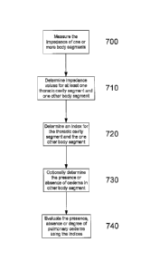
1 or Figure 3 will now be described with reference to Figure 7.
In particular, at step 700 the measuring device 1 is used to measure the
impedance of one or more
body segments. At step 710, the processing system 10 uses the measured
impedances to determine
impedance values for at least one thoracic cavity segment and one other body
segment, with these
being used in turn to determine an index for the thoracic cavity and the other
body segments at step
720.
At step 730, the processing system 20, and/or the operator of the measuring
device 1, optionally
determines the presence, absence or degree of oedema in the other body
segment. Following this, at
step 740 the indices are used to determine the presence, absence, or degree of
pulmonary oedema.
This may be achieved in a number of manners depending on the implementation as
will be described
in more detail below.
The exact manner in which the process is performed depends on the electrode
configuration used, and
hence the body segments for which impedance values are determined. A more
detailed example will
now be described with reference to Figures 8A and 8B, which sets out the
process used for the
electrode configurations of Figures 9A to 9E.
In this regard, the electrode configurations shown in Figures 9A to 9D involve
positioning electrodes
on the limbs of the subject S, with the particular electrode placement
allowing the impedance of
different body segments to be measured. Thus, for example, the impedance of a
number of limbs can
be measured. This can be achieved either in sequence, using a single channel
system, or
simultaneously, using a multi-channel system, as will be described in more
detail below.
In the examples of Figures 9A and 9B, the configuration allows the impedance
of the entire subject to
be determined, whereas the configurations shown in Figures 9C and 9D allow the
right arm 931 and
the right leg 933 to be measured respectively.
In general, when such an electrode arrangement is used, it is typical to
provide electrodes in each
possible electrode placement position, with leads being connected selectively
to the electrodes as
required. This will be described in more detail below.
It will be appreciated that this configuration uses the theory of equal
potentials, allowing the electrode
positions to provide reproducible results for impedance measurements. For
example when current is
injected between electrodes 13 and 14 in Figure 9C, the electrode 16 could be
placed anywhere along
the left arm 932, since the whole arm is at an equal potential.
CA 02613524 2007-12-27
WO 2007/002992
PCT/AU2006/000923
- 28 -
This is advantageous as it greatly reduces the variations in measurements
caused by poor placement
of the electrodes by the operator. It also greatly reduces the number of
electrodes required to perform
segmental body measurements, as well as allowing the limited connections shown
to be used to
measure each of limbs separately.
In Figure 9E an alternative electrode configuration is shown in which the
electrodes 13, 14, 15, 16 are
band electrodes extending around the subject's neck and abdomen or spot
electrodes as shown. This
electrode configuration allows direct measurement of the impedance of the
subject's thoracic cavity.
At step 800 electrodes 13, 14, 15, 16 are placed on the subject, with the
measuring device 1 operating
to apply appropriate current signals as described above, before detecting
current and voltage signals
across the limbs at multiple frequencies f1, at step 805.
In order to achieve this, the electrode placements shown in Figures 9C and 9D
are used, together with
equivalent measurements being performed for contra-lateral limbs. The manner
in which the
electrode placement is coordinated will be described in more detail below.
The current signals used will depend on the preferred implementation and as
described above could
include applying current signals at multiple frequencies either simultaneously
or in sequence, with
appropriate processing of measured signals being performed to derive the
measured voltage at each
frequency.
At step 810 the processing system 10 operates to determine the instantaneous
impedance of each limb
at each of the frequencies
At step 815 the measuring device 1 operates to determine if electrodes are
present on the thoracic
cavity.
In the event that no such electrodes are provided at step 820, the measuring
device 1 operates to detect
voltage and current signals across the entire body using the one of the
electrode configuration shown
in Figures 9A and 9B.
At step 825 the processing system 10 operates to determine the impedance of
the whole body at each
frequency f1. The measured impedance values obtained for each limb at each
frequency fi are then
subtracted from the impedance values measured at corresponding frequencies fi
for the entire body at
step 830. Subtracting the impedance measurements for each of the four limbs
from the entire body
impedance measurements provides an effective thoracic cavity impedance value
at each frequency fl.
CA 02613524 2007-12-27
WO 2007/002992
PCT/AU2006/000923
- 29 -
In the event that electrodes are present on a thoracic cavity at step 835, the
measuring device 1
operates to detect voltage and current signals across the thorax at multiple
frequencies f1, using this to
determine instantaneous impedance values for the thoracic cavity at each
frequency fi at step 840.
These values are then used to determine values for the impedance parameters Ro
and R. for each limb
and the thoracic cavity, at step 845.
In this regard, Figure 20 is an example of an equivalent circuit that
effectively models the electrical
behaviour of biological tissue. The equivalent circuit has two branches that
represent current flow
through extracellular fluid and intracellular fluid. The extracellular
component of biological
impedance is represented by Re and the intracellular component is represented
by Ri. Capacitance of
the cell membrane in the intracellular path is represented by C.
The relative magnitudes of the extracellular and intracellular components of
impedance of an
alternating current (AC) are frequency dependent. At zero frequency the
capacitor acts as a perfect
insulator and all current flows through the extracellular fluid, hence the
resistance at zero frequency,
Ro, equals R,. At infinite frequency the capacitor acts as a perfect conductor
and the current passes
through the parallel resistive combination. The resistance at infinite
frequency is given by Roo =
RiRe/(Ri+Re).
Accordingly, the impedance of the equivalent circuit of Figure 9 at an angular
frequency o.), where
co=27efrequency, is given by:
Ro¨ R.
Z R.+ ________________________________________________________ (1)
1+ (fon)
where:
R,O= impedance at infinite applied frequency = RiRe/(Ri+Re),
Ro= impedance at zero applied frequency = Re and,
T is the time constant of the capacitive circuit.
However, the above represents an idealised situation which does not take into
account the fact that the
cell membrane is an imperfect capacitor. Taking this into account leads to a
modified model in
which:
Ro¨ R.
(2)
Z = R.+ I+ _______________ (icor)(1-.)
CA 02613524 2007-12-27
WO 2007/002992
PCT/AU2006/000923
- 30 -
where a has a value between 0 and 1 and can be thought of as an indicator of
the deviation of a real
system from the ideal model.
The values of impedance parameters Ro and 12,õ may be determined in any one of
a number of
manners such as by:
= solving
simultaneous equations based on the impedance values determined at different
frequencies;
= using iterative mathematical techniques;
= extrapolation from a "Wessel plot" similar to that shown in Figure 21;
= performing a function fitting technique, such as the use of a polynomial
function.
The above described equivalent circuit models the resistivity as a constant
value and does not
therefore accurately reflect the impedance response of a subject, and in
particular does not accurately
model the change in orientation of the erythrocytes in the subject's blood
stream, or other relaxation
effects. To more successfully model the electrical conductivity of the human
body, an improved CPE
based model may alternatively be used.
In any event, it will be appreciated that any suitable technique for
determination of the parameter
values Ro and &õ may be used.
Once the parameter values Ro and Rco have been determined, the processing
system 10 operates to
determine an index / for each segment at step 850. In this example, the index
used is given by Ri/R,
and is indicative of the ratio of extracellular fluid to intracellular fluid.
In this regard, using the values for the extracellular fluid resistance R, and
intracellular fluid
resistance R.; above, the index I is given by the equation:
R R.
I = = (3)
Re R0 ¨ R.
This approach has particular application to monitoring oedema over time as a
plot of the index
against time, or comparison of the index to other references, can disclose the
onset and rate of
advance of oedema.
This is possible, as, for a healthy subject; there is generally a degree of
similarity of the extra- and
intra-cellular fluid levels, even between different body segments. Thus, for
example, if the subject is
suffering from a condition other than oedema, which causes a general change in
the ratio of extra- to
intra- cellular fluid, then this should affect all body segments roughly
equally.
CA 02613524 2007-12-27
WO 2007/002992
PCT/AU2006/000923
-31 -
At step 855 the measuring device 1 operates to optionally determine the
presence or absence of
oedema in each limb.
This may be performed in accordance with any one of a number of a techniques
including, for
example:
= comparing the index /for each of the limbs;
= medical examination; and,
= comparison of impedance parameter values and/or the index to previously
monitor values
known as a longitudinal analysis.
Thus, for example, the index / obtained for a limb can be compared to
previously determined index
values /pre, obtained for the same limb, with variations in the index over
time being indicative of the
onset of oedema.
If it is determined that oedema is present in any of the limbs at step 860,
the process moves on to step
865 with the processing system 10 operating to ignore the limb having oedema
from subsequent
analysis.
At step 870, for any limbs that do not have oedema, the processing system 10
operates to determine
an index ratio IR based on a ratio of the index determined for the thoracic
cavity with index
determined for each remaining limb. Thus, for example, if it is determined
that one leg, and both
arms are free of oedema, three index ratios IR will be determined.
As mentioned above the index / should remain relatively constant for body
regions that do not suffer
from oedema, and accordingly, assuming that none of the body segments have
oedema, then the index
ratio IR should remain relatively constant for a given individual.
In particular, assuming that the properties of each body segment are equal,
then the index ratio should
have a value in the region of 1. Typically however, minor variations in tissue
will occur between
different body segments, and this can be accounted for in different ways.
Firstly, as shown at step 875, the index ratio IR can be compared to a
predetermined range. In this
case, the range is used to account for variations between impedance of the
thoracic cavity and the
limbs, which is not attributable to pulmonary oedema. It will therefore be
appreciated that the range
is therefore typically set to take into account the difference in index ratio
IR between the thoracic
cavity and the limbs in a number of different subjects. This range can
therefore be set based on data
collected from a number of healthy subjects.
CA 02613524 2007-12-27
WO 2007/002992
PCT/AU2006/000923
- 32 -
In any event, if the index ratio IR falls outside the predetermined range,
then this is used by the
processing system 10 determine that pulmonary oedema is present in one of the
body segments at step
890.
Furthermore, an assessment of the value of the index ratio IR can be used in
assessing the degree of
pulmonary oedema. Thus, for example, a number of value ranges can be defined,
with each range
corresponding to a different degree of oedema. In this instance, the
processing system 10 can
determine within which range the index ratio IR falls, and uses this to
generate an indication of the
likely degree of pulmonary oedema.
The value of the index ratio IR will also depend on the limbs that have been
selected and accordingly,
in general a different range will be selected for the comparison depending on
the limbs under
consideration.
The index ratio IR may also depend on a number of factors, such as the
subject's age, weight, sex and
height, and again a respective range can be selected based on these factors.
However, to avoid the need for an assessment of such factors, an alternative
process of longitudinal
analysis can be performed. In this case, at step 880, the processing system 10
can compare the index
ratio IR to previously determined index ratios IRp,õ measured for the same
subject, on the same body
segments. In this situation, the previously determined index ratios IRp,, are
preferably determined
prior to the onset of pulmonary oedema, although this is not essential.
In any event, previous measurements of the index ratio based on the same limbs
on the same subject
will automatically account for inherent variations in tissue properties, which
in turn cause different
values for the ratio of extra- to intra- cellular fluid even if pulmonary
oedema is not present.
In this case, the processing system 10 assesses whether the current index
ratio IR value is different to
the previous index ratio IRprev determined for the same limb. If there is a
change in the value, then the
direction in change in value can indicate either increasing or decreasing
levels of pulmonary oedema,
with the magnitude of the change being used to indicate a degree of change at
step 890.
A further option, as set out at step 885, is to compare the index ratios IR
obtained for the different
limbs. In this instance, each of the index ratios should be approximately
equal as the index for each
limb should be identical. In this instance, if there are variations between
the index ratios IR which
exceed a predetermined statistical significance, this can indicate either a
problem with the
measurement procedure, or the presence of tissue oedema in one of the limbs,
which has been missed
at step 860 above.
CA 02613524 2007-12-27
WO 2007/002992
PCT/AU2006/000923
- 33 -
In general, at step 890, the processing system 10 will display an indication
of one or more of:
= one or more index ratios
= one or more indexes; and,
= the presence, absence or degree of pulmonary oedema.
It will therefore be appreciated from this that the above-described
methodology provides different
methods of determining the onset for oedema. This can be achieved either by
performing a
longitudinal analysis in which the index ratio IR is compared to previously
determined index ratios
IRpõõ Alternatively the index ratio IR can be compared to one or more absolute
index ratio ranges.
Additionally, further checking can be provided by comparing the index ratios
determined for the
different limbs.
In practice, a combination of the approaches may be used. Thus, for example,
when a patient is first
admitted for a procedure to be performed, a comparison to absolute index ratio
ranges may be used to
confirm that it is unlikely that the patient has pulmonary oedema.
The measured index ratio IR can then be used to form the reference value of
the index ratio IRpõõ
allowing subsequent measurements to be compared thereto.
By using the index ratio IR described above, this allows variation in tissue
properties between
different body portions to be taken into account when assessing the presence,
absence or degree of
pulmonary oedema, and accordingly, this allows the onset of pulmonary oedema
to be detected
rapidly, accurately and at an early stage.
An explanation of the process of electrode placement will now be described
with reference to Figure
10.
At step 1000 an operator of the apparatus provides details of a type of
impedance measurement to be
performed to the monitoring unit. Thus, for example, the operator will
indicate that a pulmonary
oedema assessment is to be performed, as well as indicating whether or not
electrodes will be
provided on the thorax as shown in Figure 9E.
At step 1010 the operator positions electrodes on the subject, typically at
each position where
electrodes will be required during the measurement process. Following this the
operator connects
leads to the electrodes based on connection instructions provided by the
monitoring unit at step 1020.
It will therefore be appreciated that this may be achieved in a number of ways
and that typically, this
involves having the measuring device 1 present a list of the available
measurement types and allow
CA 02613524 2007-12-27
WO 2007/002992
PCT/AU2006/000923
- 34 -
the user to select the measurement type of interest. This can then be used to
access a profile
specifying the required electrode arrangement, which is then displayed to the
user, allowing the user
to correctly connect the electrodes.
At step 1030 the measuring device 1 will operate to perform impedance
measurements by generating
an appropriate current sequence and applying this to the subject via the
electrodes 13, 14.
At step 1040 the measuring device 1 determines if further impedance
measurements are required and
if so the process returns to step 1010 to allow the operator to connect leads
to different electrodes as
required. This process is repeated until sufficient impedance measurements
have been collected to
perform the required analysis.
At this stage, the process moves on to step 1050 with the monitoring unit
operating to process the
impedance measurements and provide an indication of required information to
the operator, as
described above.
An example of an electrode connection apparatus that may be used in this
process is shown in Figures
11A and 11B.
In particular, in this example, the connector includes circuitry provided on a
substrate such as a PCB
(Printed Circuit Board) 1161, which is in turn mounted in a housing 1160 as
shown. The housing
1160 includes an arm 1162 which is urged toward a contact 1163 provided on the
substrate 1161. The
substrate 1161 is then coupled to a respective one of the ADCs 37, 38 or the
DAC 39, via appropriate
leads shown generally at L, such as the leads 41, 42, 53, 54.
In use, the connector couples to a conductive electrode substrate 1165, such
as a plastic coated in
silver, and which in turn has a conductive gel 1164, such as silver/silver
chloride gel thereon. The
arm 1162 urges the conductive electrode substrate 1165 against the contact
1163, thereby electrically
coupling the conductive gel 1164 to the circuit provided on the substrate
1161.
This ensures good electrical contact between the measuring device 1 and the
subject S, as well as
reducing the need for leads between the electrodes 15, 16 and the input of the
voltage buffers,
removing the requirement for additional leads, which represents an expense, as
well as a source of
noise within the apparatus.
In this example, the edges and corners of the housing 1160, the arm 1162 and
the substrate 1165 are
curved. This is to reduce the chance of a subject being injured when the
connector is attached to the
CA 02613524 2007-12-27
WO 2007/002992
PCT/AU2006/000923
- 35 -
electrode. This is of particular importance when using the electrodes on
oedema suffers, when even a
small nip of the skin can cause severe complications.
To further enhance the useability of the housing, the housing may be formed
from a material that has
a low coefficient of friction and/or is spongy or resilient. Again, these
properties help reduce the
likelihood of the subject being injured when the housing is coupled to the
electrode.
Electrode Configuration
An example of an alternative electrode configuration will now be described
with reference to Figures
12A and 12B.
In this example, the electrode connector is formed from a housing 1200 having
two arms 1201, 1202
arranged to engage with an electrode substrate 1205 to thereby couple the
housing 1200 to the
substrate 1205. A contact 1203 mounted on an underside of the arm 1202, is
urged into contact
and/or engagement with an electrode contact 1204 mounted on a surface of the
electrode substrate
1205. The electrode also includes a conductive gel 1206, such as a
silver/silver chloride gel,
electrically connected to the contact 1204. This can be achieved, either by
using a conductive track,
such as a silver track, or by using a conductive substrate such as plastic
coated in silver.
This allows the lead L to be electrically connected to the conductive gel
1206, allowing current to be
applied to and/or a voltage measured from the subject S to which they are
attached. It will be
appreciated that the above housing 1200 may contain the buffer circuit 50 or
part of the current source
circuit, in a manner similar to that described above.
Alternatively more complex interconnections may be provided to allow the
measuring device 1 to
identify specific electrodes, or electrode types.
This can be used by the measuring device 1 to control the measurement
procedure. For example,
detection of an electrode type by the processing system 2 may be used to
control the measurements
and calculation of different impedance parameters, for example to determine
indicators for use in
detecting oedema, monitoring cardiac function, or the like.
Similarly, electrodes can be provided with visual markings indicative of the
position on the subject to
which the electrode should be attached. For example a picture of a left hand
can be shown if the
electrode pad is to be attached to a subject's left hand. In this instance,
identification of the electrodes
can be used to allow the measuring device 1 to determine where on the subject
the electrode is
attached and hence control the application and measurement of signals
accordingly.
CA 02613524 2007-12-27
WO 2007/002992
PCT/AU2006/000923
- 36 -
An example of this will now be described with reference to Figures 12C to 12G.
In this example the
contact 1203 is formed from a contact substrate 1220, such as a PCB, having a
number of connector
elements 1221, 1222, 1223, 1224, formed from conductive contact pads,
typically made of silver or
the like. The connector elements are connected to the lead L via respective
electrically conductive
tracks 1226, typically formed from silver, and provided on the contact
substrate 1220. The lead L
includes a number of individual wires, each electrically coupled to a
respective one of the connector
elements 1221, 1222, 1223, 1224.
In this example the electrode contact 1204 on the electrode substrate 1205
typically includes an
electrode contact substrate 1230, including electrode connector elements 1231,
1232, 1233, 1234,
typically formed from silver contact pads or the like. The electrode connector
elements 1231,... 1234
are positioned so that, in use, when the electrode connector 1200 is attached
to an electrode, the
connector elements 1221...1224 contact the electrode connector elements
1231,... 1234 to allow
transfer of electrical signals with the measuring device 1.
In the examples, of Figures 12D to 12G, the connector element 1231 is
connected to the conductive
gel 1206, via an electrically conductive track 1236, typically a silver track
that extends to the
underside of the electrode substrate 1205. This can be used by the measuring
device 1 to apply a
current to, or measure a voltage across the subject S.
Additionally, selective ones of the connector elements 1232, 1233, 1234 are
also interconnected in
four different arrangements by respective connectors 1236A, 1236B, 1236C,
1236D. This allows the
measuring device 1 to detect which of the electrode contacts 1222, 1223, 1224
are interconnected, by
virtue of the connectors, 1236A, 1236B, 1236C, 1236D, with the four different
combinations
allowing the four different electrodes to be identified.
Accordingly, the arrangement of Figures 12D to 12G can be used to provide four
different electrodes,
used as for example, two current supply 13, 14 and two voltage measuring
electrodes 15, 16.
In use, the measuring device 1 operates by having the second processing system
17 cause signals to
be applied to appropriate wires within each of the leads L, allowing the
conductivity between the
connecting elements 1222, 1223, 1224, to be measured. This information is then
used by the second
processing system 17 to determine which leads L are connected to which of the
electrodes 13, 14, 15,
16.
CA 02613524 2007-12-27
WO 2007/002992
PCT/AU2006/000923
- 37 -
This allows the first processing system 10 or the second processing system 17
to control a multiplexer
to connect the electrodes 13, 14, 15, 16 to the signal generator 12, or the
signal sensor 12, as will now
be described with respect to Figure 13.
In this example, the measuring device 1 includes a switching device 18, such
as a multiplexer, for
connecting the signal generator 11 and the sensor 12 to the leads L. This
allows the measuring device
1 to control which of the leads L are connected to the signal generator 11 and
the sensor 12.
In this example, the individual applying the electrode pads to the subject can
simply position the
electrodes 13, 14, 15, 16 on the subject in the position indicated by visual
markings provided thereon.
Leads may then be connected to each of the electrodes allowing the measuring
device 1 to
automatically determine to which electrode 13, 14, 15, 16 each lead L
connected and then apply
current signals and measure voltage signals appropriately. This avoids the
complexity of ensuring the
correct electrode pads are connected via the correct leads L.
It will be appreciated that the above described process allows electrode
identification simply by
applying currents to the electrode connector. However, other suitable
identification techniques can be
used, such as through the use of optical encoding. This could be achieved for
example, by providing
a visual marker, or a number of suitably arranged physical markers on the
electrode connector 1104,
or electrode substrate 1105. These could then be detected using an optical
sensor mounted on the
connector 1100, as will be appreciated by persons skilled in the art.
Alternatively, electrodes may be
identified by an encoded value represented by a component such as a resistor
or capacitor having a
predetermined value.
A second detailed example of a process for determining pulmonary oedema will
now be described
with reference to Figure 13.
In particular, in this example, the process is performed using the electrode
band shown in cross
section in Figures 14A and 14B. As shown, the band electrode is formed from a
band 1440 having a
number of electrodes 1441A, ... 41F provided thereon. In use, the band 1440 is
adapted to be worn
by the subject around the level of the xiphoid process, thereby allowing
impedance measurements to
be made directly from the subject's thoracic cavity. In this regard, each of
the electrodes may be used
as current or voltage electrodes as will be described.
In this example, at step 1500 the band 1440 is attached to the subject's
thoracic cavity, with the
measuring device 1 operating to apply a current signal across two of the
electrodes at step 1510. In
CA 02613524 2007-12-27
WO 2007/002992
PCT/AU2006/000923
- 38 -
the example of Figure 7A, the current supply is applied to the electrodes
1441A, 1441D so that the
electrodes 1441A, 1441D act as the current supply electrodes 13, 14.
At step 1520, the measuring device 1 operates to measure the potential
generated at each of the other
electrodes 1441C, 1441D, 1441E, 1441F. The potentials are measured with
respect to a common
reference potential thereby allowing the potential measured at each electrode
to be compared.
In particular, given the electrode configuration shown in Figure 7A, it is
apparent that the potentials
generated at the electrodes 1441B, 1441F and similarly at the electrodes
1441C, 1441E will be
identical, assuming a symmetrical impedance response for the subject's
thoracic cavity. However,
this allows comparison of the potentials between the electrodes, 1441C, 1441F,
and between the
electrodes 1441B, 1441E, as indicated at 1443, 1442 respectively.
By comparing the results of these comparisons, this allows the potential in a
thoracic cavity segment
1444 to be determined, which in turn allows the first or second processing
systems 10, 17 to
determine impedance values for the cavity segment 1444 at step 1530.
It will be appreciated that when alternative electrode configurations are
used, as shown for example in
Figure 14B, this allows different potential comparisons to be performed, which
in turn allows the
impedance of different thoracic cavity segments to be performed. Thus, for
example, in the
configuration shown in Figure 14B, the electrodes 1441A, 1441C are used as the
current supply
electrodes, with potentials being measured at the electrodes 1441B, 1441D,
1441E, 1441F. This
allows potential differences between the electrodes 1441B, 1441D; 1441B,
1441F; 1441D, 1441F;
1441B, 1441E, to be determined, as shown at 1445; 1446; 1447; 1448, thereby
allowing impedance
values to be determined for the cavity segments 1449, 1450.
Accordingly, this technique can utilise each possible electrode configuration,
in other words with each
possible pair of the electrodes 1441A, ..,, 1441F being used for current
supply, allowing the
impedance of a number of different cavity segments to be measured. It is also
envisaged that all EIT
approaches used to calculate the conductivity or impedances of thoracic
segments known to people
skilled in the art are envisaged to be contained in the scope of this
disclosure.
Accordingly, at step 1554 the measuring device 1 determines if all possible
electrode arrangements
have been used and if not causes current signals to be applied to different
electrodes 1441, with
corresponding measurements and comparisons being performed at step 1020 and
1030.
Once measurements have been performed for all possible electrode
configurations, the processing
system 10 operates to determine parameter values Ro, Roo for each possible
cavity segment at step
CA 02613524 2007-12-27
WO 2007/002992
PCT/AU2006/000923
-39-
1560. These parameter values are then used to determine an index for each
cavity segment at step
1570. Whilst any index may be used, this is typically an index based on the
ratio of the extra- to intra-
cellular fluid, which can therefore be determined in a manner similar to that
described above with
respect to step 800 above.
At step 1580 the indices are used to evaluate the absence, presence or degree
of oedema.
This may be achieved in a number of manners depending on the preferred
implementation.
Thus, for example, this could be achieved by comparing the determined index
values Ito previously
determined index values /põõ such as measurements made before the onset of
pulmonary oedema,
thereby providing a form of longitudinal analysis, or by comparing the index
values to predetermined
reference ranges. Thus this can be performed in a manner similar to that
described above with respect
to steps 875 and 880.
Alternatively, the indices can be compared to each other directly. In this
instance, it will be
appreciated that if one of the thoracic cavity segments has an index value
that is significantly different
to the index values obtained for other cavity segments, then this indicates
not only the presence of
pulmonary oedema, but also its location.
In the above described example, six electrodes 1441 only are showed for
clarity. However, it will be
appreciated that any number of electrodes may be used, with a greater number
of electrodes allowing
a greater number of thoracic cavity segments to be analysed. This in turn can
be used to provide a
greater resolution and consequently, an improved diagnostic ability.
Additionally, whilst the band electrode is shown to extend all the way around
the subject, this is not
essential. In particular, in some applications, it is not possible to raise
the subject from a surface, such
as a bed, to allow the electrode band to be attached to the patient. In this
instance, the electrode band
could be adapted to extend only partially around the subjects thoracic cavity,
as will be described in
more detail below.
In this instance, or when an entire electrode band is used, it is also
possible to provide multiple
electrode bands spaced along the length of the thoracic cavity, thereby
further enhancing the
resolution of the detection process.
A further issue with the use of such band electrodes is that there can be
significant variation in the
thoracic cavity configuration during the respiration cycle. Accordingly it is
typical for the current
signal to use superposed signals, so that the impedances for each of the
frequencies fi can be measured
CA 02613524 2007-12-27
WO 2007/002992
PCT/AU2006/000923
-40 -
substantially simultaneously, thereby ensuring that variations in cavity
configuration do not have an
impact on any given impedance measurement.
In this instance, a further enhancement is to repeatedly measure the impedance
of a given segment
during the respiration process, thereby allowing variations in the impedance
throughout the
respiration cycle to be monitored. This can in turn be used to further enhance
the detection of
pulmonary oedema.
In order to implement this process, it will be appreciated that the band
electrode may include a
number of potential lead connections, with leads being connected to the band
electrode manually, for
example using a technique similar to that described above with respect to
Figure 10.
Preferably however an automated system is used in which leads are connected to
each of the
electrodes 1441 allowing automatic current application and measurement at the
appropriate
electrodes.
This may be achieved utilising apparatus shown in Figure 16. In particular,
this is similar to the
apparatus shown in Figure 1, but in this example includes a multiplexer 51
coupled to each of the
electrodes by corresponding leads 53, 54 as shown.
In use, the multiplexing of signals can be controlled by the processing system
10, or the second
processing system 17 if present, thereby allowing the measuring device 1 to
apply a current to each
possible electrode pair in turn, measuring the resulting potentials at each of
the remaining electrodes
automatically.
This has the added advantage of allowing a band electrode to be placed on the
subject's abdomen with
measurements being performed rapidly and automatically by the measuring device
1. This makes the
apparatus and method suitable for home care applications in which individuals
at risk of pulmonary
oedema are provided with their own measuring device 1 and instructed how to
take their own
measurements. This can be achieved simply by wearing the band electrode and
then activating the
measuring device 1, it will be appreciated that this provides a simple
mechanism for inexperienced
individuals to take their own readings and be alerted in the event that
pulmonary oedema is a risk.
Band Electrode Example
An example of an alternative electrode configuration will now be described
with reference to Figures
17A to 17F. In this particular example the electrode is a band electrode 1700,
which includes a
CA 02613524 2007-12-27
WO 2007/002992
PCT/AU2006/000923
- 41 -
number of separate electrodes. In this example the electrode is formed from an
elongate substrate
1710 such as a plastic polymer coated with shielding material and an
overlaying insulating material.
A number of electrically conductive tracks 1720 are provided on the substrate
extending from an end
of the substrate 1711 to respective conductive contact pads 1730, spaced apart
along the length of the
substrate in sequence. This allows a connector similar to the connectors
described above, but with
corresponding connections, to be electrically coupled to the tracks 1220.
The tracks 1720 and the contact pads 1730 may be provided on the substrate
1710 in any one of a
number of manners, including for example, screen printing, inkjet printing,
vapour deposition, or the
like, and are typically formed from silver or another similar material. It
will be appreciated however
that the tracks and contact pads should be formed from similar materials to
prevent signal drift.
Following the application of the contact pads 1730 and the tracks 1720, an
insulating layer 1740 is
provided having a number of apertures 1750 aligned with the electrodes contact
pads 1730. The
insulating layer is typically formed from a plastic polymer coated with
shielding material and an
overlaying insulating material.
To ensure adequate conduction between the contact pads 1730, and the subject
S, it is typical to apply
a conductive gel 1760 to the contact pads 1730. It will be appreciated that in
this instance gel can be
provided into each of the apertures 1750 as shown.
A removable covering 1770 is then applied to the electrode, to maintain the
electrode's sterility and/or
moisture level in the gel. This may be in the form of a peel off strip or the
like which when removed
exposes the conductive gel 1760, allowing the electrode to be attached to the
subject S.
In order to ensure signal quality, it is typical for each of the tracks 1720
to comprise a shield track
1721, and a signal track 1722, as shown. This allows the shield on the leads
L, such as the leads 41,
42, 51 to be connected to the shield track 1721, with the lead core being
coupled to the signal track
1722. This allows shielding to be provided on the electrode, to help reduce
interference between
applied and measured signals.
This provides a fast straight-forward and cheap method of producing band
electrodes. It will be
appreciated that similar screen printing techniques may be utilised in the
electrode arrangements
shown in Figures 11A and 11B, and 12A-12G.
The band electrode may be utilised together with a magnetic connector as will
now be described with
respect to Figures I7G and 17H. In this example, the band electrode 1700
includes two magnets
CA 02613524 2007-12-27
WO 2007/002992
PCT/AU2006/000923
- 42 -
1701A, 1701B positioned at the end 1711 of the substrate 1710. The connector
is formed from a
connector substrate 1780 having magnets 1781A, 1781B provided therein.
Connecting elements 1782
are also provided, and these would in turn be connected to appropriate leads
L.
The magnets 1701A, 1781A; 1701B (not shown for clarity), 1781B can be arranged
to align and
magnetically couple, to urge the connector substrate 1780 and the band
electrode 1700 together.
Correct alignment of the poles of the magnets 1701A, 1781A; 1701B, 1781B can
also be used to
ensure both the correct positioning and orientation of the connector substrate
1780 and band
electrode, which can ensure correct alignment of the connecting elements 1781,
with corresponding
ones of the tracks 1720, on the band electrode 1700.
It will be appreciated that this can be used to ensure correct connection with
the electrode, and that a
similar magnetic alignment technique may be used in the connectors previously
described.
In use, the band electrode may be attached to the subject's torso, as shown in
Figure 171. The
electrode will typically include an adhesive surface, allowing it to stick to
the subject. However, a
strap 1780 may also be used, to help retain the electrode 1700 in position.
This provides an electrode
that is easy to attach and position on the subject, and yet can be worn for an
extended period if
necessary. The band electrode 1700 may also be positioned on the subject at
other locations, such as
on the side of the subject's torso, or laterally above the naval, as shown.
The band electrode 1700 provides sufficient electrodes to allow cardiac
function to be monitored. In
the above example, the band electrode includes six electrodes, however any
suitable number may be
used, although typically at least four electrodes are required.
Variable Current
A further feature that can be implemented in the above measuring device is the
provision of a signal
generator 11 capable of generating a variable strength signal, such as a
variable current. This may be
used to allow the measuring device 1 to be utilised with different animals,
detect problems with
electrical connections, or to overcome noise problems.
In order to achieve this, the current source circuit shown in Figure 4 is
modified as shown in Figure
18. In this example, the resistor R10 in the current source circuit of Figure
4 is replaced with a variable
resistor VRio. Alteration of the resistance of the resistor VRio will result
in a corresponding change in
the magnitude of the current applied to the subject S.
CA 02613524 2007-12-27
WO 2007/002992
PCT/AU2006/000923
- 43 -
To reduce noise and interference between the current source circuit and the
control, which is typically
achieved using the second processing module 17, it is typical to electrically
isolate the variable
resistor 17 from the control system. Accordingly in one example, the variable
resistor VRio is formed
from a light dependent resistor. In this example, a light emitting diode (LED)
or other illumination
source can be provided, as shown at LI. The LED L1 can be coupled to a
variable power supply P of
any suitable form. In use, the power supply P, is controlled by the second
processing module 17,
thereby controlling the intensity of light generated by the LED LI, which in
turn allows the resistance
VRio, and hence the applied current, to be varied.
In order to operate the measuring device 1, the first processing system 10 and
the second processing
system 17 typically implement the process described in Figure 19. In this
example, at step 1900 the
user selects a measurement or an animal type utilising the input/output device
22.
At step 1910 the first processing system 10 and the second processing system
17 interact to determine
one or more threshold values based on the selected measurement or animal type.
This may be
achieved in any one of a number of ways, such as by having the first
processing system 10 retrieve
threshold values from the memory 21 and transfer these to the second
processing system 17, although
any suitable mechanism may be used. In general, multiple thresholds may be
used to specify different
operating characteristics, for signal parameters such as a maximum current
that can be applied to the
subject S, the minimum voltage required to determine an impedance measurement,
a minimum signal
to noise ratio, or the like.
At step 1920 the second processing system 17 will activate the signal
generator 11 causing a signal to
be applied to the subject S. At step 1930 the response signal at the
electrodes 15,16 is measured using
the sensor 12 with signals indicative of the signal being returned to the
second processing system 17.
At step 1940 the second processing system 17 compares the at least one
parameter of the measured
signal to a threshold to determine if the measured signal is acceptable at
step 1950. This may involve
for example determining if the signal to noise levels within the measured
voltage signal are above the
minimum threshold, or involve determining if the signal strength is above a
minimum value.
If the signal is acceptable, impedance measurements can be performed at step
1960. If not, at step
1970 the second processing system 17 determines whether the applied signal has
reached a maximum
allowable. If this has occurred, the process ends at step 1990. However, if
the maximum signal has
not yet been reached, the second processing system 17 will operate to increase
the magnitude of the
current applied to the subject S at step 1980 before returning to step 1930 to
determine a new
measured signal.
CA 02613524 2007-12-27
WO 2007/002992
PCT/AU2006/000923
-44 -
Accordingly, this allows the current or voltage applied to the subject S to be
gradually increased until
a suitable signal can be measured to allow impedance values to be determined,
or until either a
maximum current or voltage value for the subject is reached.
It will be appreciated that the thresholds selected, and the initial current
applied to the subject S in
step 1420 will typically be selected depending on the nature of the subject.
Thus, for example, if the
subject is a human it is typical to utilise a lower magnitude current than if
the subject is an animal
such as a mouse or the like.
Lead Calibration
To assist in interpreting the impedance measurements, it is useful to take
into account electrical
properties of the connecting leads and associated circuitry.
To achieve this, the leads and corresponding connections can be encoded with a
value representing
calibration information. This can include, for example, using specific values
for respective ones of
the resistors in the current source, or buffer circuits shown in Figures 4 and
5. Thus for example, the
value of the resistors R12, R131 R26 can be selected based on the properties
of the corresponding leads.
In this instance, when the leads are connected to the measuring device 1, via
the corresponding ADCs
37, 38, the processing modules 32, 33 can interrogate the circuitry using
appropriate polling signals to
thereby determine the value of corresponding resistor. Once this value has
been determined, the
second processing system 17 can use this to modify the algorithm used for
processing the voltage and
current signals to thereby ensure correct impedance values are determined.
In addition to this, the resistance value can also act as a lead identifier,
to allow the measuring device
to identify the leads and ensure that only genuine authorised leads are
utilised. Thus, for example, if
the determined resistance value does not correspond to a predetermined value
this can be used to
indicate that non-genuine leads are being used. In this instance, as the lead
quality can have an effect
on the accuracy of the resultant impedance analysis, it may desirable to
either generate an error
message or warning indicating that incorrect leads are in use. Alternatively,
the second processing
system 17 can be adapted to halt processing of the measured current and
voltage signals. This allows
the system to ensure that only genuine leads are utilised.
This can farther be enhanced by the utilisation of a unique identifier
associated with each lead
connection circuit. In this instance, a unique identifier can be encoded
within an IC provided as part
of the current source or voltage buffer circuits. In this instance, the
measuring device 1 interrogates
CA 02613524 2007-12-27
WO 2007/002992
PCT/AU2006/000923
- 45 -
the unique identifier and compared to unique identifiers stored either in
local memory, or in a central
database, allowing genuine leads to be identified.
This process can also be used to monitor the number of times a lead has been
used. In this instance,
each time a lead is used, data reflecting lead usage is recorded. This allows
the leads to have a
predesignated use quota life span, and once the number of times the lead is
used reaches the quota,
further measurements using the leads can be prevented. Similarly, a temporal
limitation can be
applied by providing an expiry date associated with the lead. This can be
based on the date the lead is
created, or first used depending on the preferred implementation.
It will be appreciated that when recording lead usage, issues may arise if
this is recorded locally. In
particular, this could allow a lead to be re-used with a different measuring
device. To avoid this, the
leads can be configured with an ID which is set by the measuring device on
first use. This can be
used to limit usage of the leads to a single measuring device.
This can be used to ensure that the leads are correctly replaced in accordance
with a predetermined
lifespan thereby helping to ensure accuracy of measure impedance values.
Device Updates
An example of a process for updating the measuring device will now be
described with reference to
Figure 22.
In one example, at step 2200 the process involves determining a measuring
device 1 is to be
configured with an upgrade, or the like, before configuration data is created
at step 2210. At step
2220 the configuration data is typically uploaded to the device before the
device is activated at 2230.
At 2240 when the device commences operation the processing system 2 uses the
configuration data to
selectively activate features, either for example by controlling the upload of
instructions, or by
selectively activating instructions embedded within the processing system 2 or
the controller 19.
This can be achieved in one of two ways. For example, the configuration data
could consist of
instructions, such as a software or firmware, which when implemented by the
processing system 2
causes the feature to be implemented. Thus, for example, this process may be
utilised to update the
operation of the firmware provided in the second processing system 17, the
processing system 10 or
the controller 19 to allow additional functionality, improved measuring
algorithms, or the like, to be
implemented.
CA 02613524 2007-12-27
WO 2007/002992
PCT/AU2006/000923
-46 -
Alternatively, the configuration data could be in the form of a list of
features, with this being used by
the processing system 2 to access instructions already stored on the measuring
device I. Utilisation of
configuration data in this manner, allows the measuring device to be loaded
with a number of as yet
additional features, but non-operational features, when the device is sold. In
this example, by
updating the configuration data provided on the measuring device 1, this
allows these further features
to be implemented without requiring return of the measuring device 1 for
modification.
This is particularly useful in the medical industry as it allows additional
features to be implemented
when the feature receives approval for use. Thus, for example, techniques may
be available for
measuring or detecting lymphoedema in a predetermined way, such as through the
use of a particular
analysis of measured voltage signals or the like. In this instance when a
device is sold, approval may
not yet have been obtained from an administering body such as the Therapeutic
Goods
Administration, or the like. Accordingly, the feature is disabled by
appropriate use of a configuration
data. When the measurement technique subsequently gains approval, the
configuration data can be
modified by uploading a new updated configuration data to the measuring
device, allowing the feature
to be implemented.
It will be appreciated that these techniques may be used to implement any one
of a number of
different features, such as different measuring techniques, analysis
algorithms, reports on results of
measured impedance parameters, or the like.
An example of a suitable system for providing updates will now be described
with respect to Figure
23. In this example, a base station 2300 is coupled to a number of measuring
devices 1, and a number
of end stations 2303 via a communications network 2302, such as the Internet,
and/or via
communications networks 2304, such as local area networks (LANs), or wide area
networks (WANs).
The end stations are in turn coupled to measuring devices 1, as shown.
In use, the base station 2300 includes a processing system 2310, coupled to a
database 2311. The
base station 2300 operates to determine when updates are required, select the
devices to which
updates are applied, generate the configuration data and provide this for
update to the devices 1. It
will be appreciated that the processing system 2310 may therefore be a server
or the like.
This allows the configuration data to be uploaded from the server either to a
user's end station 2303,
such as a desk top computer, lap top, Internet terminal or the like, or
alternatively allows transfer from
the server via the communications network 2302, 2304, such as the Internet. It
will be appreciated
that any suitable communications system can be used such as wireless links, wi-
fl connections, or the
like.
=
CA 02613524 2007-12-27
WO 2007/002992
PCT/AU2006/000923
- 47 -
In any event, an example of the process of updating the measuring device 1
will now be described in
more detail with reference to Figure 24. In this example, at step 2400 the
base station 2300
determines that there is a change in the regulatory status of features
implemented within a certain
region. As mentioned above this could occur for example following approval by
the TGA of new
features.
The base station 2300 uses the change in regulatory status to determine new
features available at step
2410, before determining an identifier associated with each measuring device 1
to be updated at step
2420. As changes in regulatory approval are region specific, this is typically
achieved by having the
base station 2300 access database 2311 including details of the regions in
which each measuring
device sold are used. The database 2311 includes the identifier for each
measuring device 1, thereby
allowing the identifier of each measuring device to be updated to be
determined.
At step 2430, the base station 2300 determines the existing configuration
data, typically from the
database 2311, for a next one of the measuring devices 1, before modifying the
configuration data to
implement the new features at step 2440. The configuration data is then
encrypted utilising a key
associated with the identifier. The key may be formed from a unique prime
number associated with
the serial number, or partially derived from the serial number, and is
typically stored in the database
2311, or generated each time it is required using a predetermined algorithm.
At step 2460 the encrypted configuration data is transferred to the measuring
device 1 as described
above.
At step 2470 when the device restarts and the first processing system 10 is
activated, the first
processing system 10 determines the encryption key, and uses this to decrypt
the configuration data.
This may be achieved in any one of a number of ways, such as by generating the
key using the serial
number or other identifier, and a predetermined algorithm. Alternatively, this
may be achieved by
accessing a key stored in the memory 21. It will be appreciated that any form
of encryption may be
used, although typically strong encryption is used, in which a secret key is
used to both encrypt and
decrypt the configuration data, to thereby prevent fraudulent alteration of
the configuration by users,
as will be explained in more detail below.
At step 2480, the first processing system 10 activates software features
within the second processing
system 24 using the decrypted configuration data.
It will therefore be appreciated that this provides a mechanism for
automatically updating the features
available on the measuring device. This may be achieved either by having the
second processing
CA 02613524 2007-12-27
WO 2007/002992
PCT/AU2006/000923
- 48 -
system 24 receive new firmware from the processing system 10, or by activating
firmware already
installed on the second processing system 24, as described above.
As an alternative to performing this automatically when additional features
are approved for use, the
process can be used to allow features to be activated on payment of a fee. In
this example, a user may
purchase a measuring device 1 with limited implemented functionality. By
payment of a fee,
additional features can then be activated as and when required by the user.
In this example, as shown in Figure 25, when the user selects an inactive
feature at step 2500, the first
processing system 10 will generate an indication that the feature is
unavailable at step 2510. This
allows the user to select an activate feature option at step 2520, which
typically prompts the user to
provide payment details at step 2530. The payment details are provided to the
device manufacturer in
some manner and may involve having the user phone the device manufacturer, or
alternatively enter
the details via a suitable payment system provided via the Internet or the
like.
At step 2540, once the payment is verified, the process can move to step 2420
to allow an automatic
update to be provided in the form of a suitable configuration data. However,
if payment details are
not verified the process ends at 2550.
It will be appreciated by a person skilled in the art that encrypting the
configuration data utilising a
unique identifier means that the configuration data received by a measuring
device 1 is specific to that
measuring device. Accordingly, the first processing system 10 can only
interpret the content of a
configuration data if it is both encrypted and decrypted utilising the correct
key. Accordingly, this
prevents users exchanging configuration data, or attempting to re-encrypt a
decrypted file for transfer
to a different device.
It will be appreciated that in addition to, or as an alternative to simply
specifying features in the
configuration data, it may be necessary to upload additional firmware to the
second processing system
24. This can be used for example, to implement features that could not be
implemented using the
firmware shipped with the measuring device 1.
In this example, it would be typical for the configuration data to include any
required firmware to be
uploaded, allowing this to be loaded into the second processing system 24,
using the first processing
system 10. This firmware can then either be automatically implemented, or
implemented in
accordance with the list of available features provided in the configuration
data.
It will be appreciated that this provides a mechanism for updating and/or
selectively activating or
deactivating features, such as measuring protocols, impedance analysis
algorithms, reports
CA 02613524 2014-08-12
- 49 -
interpreting measured results, or the like. This can be performed to ensure
the measuring device
conforms to existing TGA or FDA approvals, or the like.
The end station 2303 can effectively perform any one or more of tasks
performed by the first processing
system 10 in the examples throughout the specification. Accordingly, the
device could be provided
without the first processing system 10, with the functionality usually
performed by the first processing
system 10 being performed by an end station 2303. In this arrangement, the end
station 2303 therefore
effectively forms part or all of the first processing system 10. This allows
the measuring device 1 to be
provided including only the second processing system 17 coupled directly to
the external interface 23 to
allow the measuring device 1 to be controlled by the end station 2303. This
would typically be achieved
via the use of suitable applications software installed on the end station
2303.
The scope of the invention as defined by the attached claims should not be
limited by the specific
embodiments set forth in the examples, but should be given the broadest
interpretation consistent with
the specification as a whole.
Thus, for example, it will be appreciated that features from different
examples above may be used
interchangeably where appropriate. Furthermore, whilst the above examples have
focussed on a subject
such as a human, it will be appreciated that the measuring device and
techniques described above can be
used with any animal, including but not limited to, primates, livestock,
performance animals, such race
horses, or the like.
The above described processes can be used for diagnosing the presence, absence
or degree of a range of
conditions and illnesses, including, but not limited to oedema, pulmonary
oedema, lymphoedema, body
composition, cardiac function, and the like.
It will also be appreciated above described techniques, such as electrode
identification, device updates
and the like may be implemented using devices that do not utilise the separate
first processing system 10
and second processing system 17, but rather use a single processing system 2,
or use some other internal
configuration.