Note: Descriptions are shown in the official language in which they were submitted.
CA 02613685 2007-12-28
WO 2007/000025 PCT/AU2006/000904
1
AUTOMATED INSECT DETERRENT PUMP SPRAY APPLICATOR
Field of the Invention.
The present invention relates to bins and particularly to the control of
insects and unwanted odours around bins and other rubbish collection devices.
Background Art.
Dispensers for dispensing various materials into a container designed
for collection of rubbish and refuse are commercially available. In addition
to this,
there are devices available for dispensing various materials in situations
where
distasteful odours are present such as over rubbish tips and in toilets and
the like.
The dual problems of resulting health hazards and unpleasant odours
often coexist in most garbage storage areas, since rotting garbage often
produces
scents which are unpleasant to humans, but which attract pests which
themselves carry
diseases.
United States Patent No. 4,047,775 to Wolbrink discloses a trash
compactor which incorporates a deodorizer for continually releasing a scent to
the air
in the compactor cabinet to mask odours emanating from the compacted trash.
Unfortunately Wolbrink simply masks the odours fiom the trash, but does
nothing to
prevent pests from infesting the garbage therein.
Another device is disclosed in United States Patent No. 3,840,145 to
Almanza which also contains a useful discussion of some of the problems
associated
with devices of this type. A portion of the Background Art section of the
Almanza
patent follows verbatim:
"A large number of devices for dispensing a chemical agent into a
refuse receptacle for the purpose of disinfecting, deodorizing, and/or
destroying or
repelling insects have been pf oposed and constructed in the past. One such
dispensing device is disclosed in U.S. Pat. No. 1,223,760 whei-ein a
substantially
annular container having a central opening is secured on the underside of the
lid of a
refuse receptacle. The container defines an annular reseyvoir for containing
disinfectant. The fumes from the disinfectant flow downwardly from the lid
into the
receptacle through tlze central opening in the dispensing device. One
disadvantage of
this type of disinfectant dispenserfor refuse receptacles is its inability to
prevent the
disinfectant from spilling or flowing from the dispenser upon movement of the
receptacle or for example lifting the coverfi om the receptacle and canting
the same.
CA 02613685 2007-12-28
WO 2007/000025 PCT/AU2006/000904
2
That is, the disinfectant will tend to drain through tlae central opening upon
naovement
of the cover fi=om its nornaal horizontal position. Further, this dispenser
does not
effectively distribute the disinfectant as it is not directly exposed to the
contents of the
receptacle.
Another= dispenser for a like purpose is disclosed in U.S. Pat. No.
1,682,491. In that patent, sheet metal is bent to form a dome having
upstanding
peripheral sides. Tlae dome and sides thereof are perforated and tlze space
between
the cover and the dome defines an annular chamber in which is placed an
absorbent
material and a disinfectant. This dispenser is secured to the underside of a
garbage
can cover. However, by perforating the sides and tlae dome of this dispenser,
the
disinfectant is readily drawn off requiring the container to be filled at
frequent
intervals. Other dispensers similar to the foregoing for like purposes are
disclosed in
U.S. Pat. Nos. 1, 490, 314; 999,912; 2, 571, 428; and 2, 531, 084. The devices
disclosed
in these patents, however, have similar disadvantages as the devices of the
above
specifically noted patents as well as other and various disadvantages."
Therefore, it would be advantageous to the development of the art if a
device were available which is inexpensive, robust, easy to use and did not
require
constant attention or maintenance.
It will be clearly understood that, if a prior art publication is referred to
herein, this reference does not constitute an admission that the publication
forms part
of the common general knowledge in the art in Australia or in any other
country.
Summary of the Invention.
The present invention is directed to an automated insect deterrent pump
spray applicator, which may at least partially overcome at least one of the
abovementioned disadvantages or provide the consumer with a useful or
commercial
choice.
In one form, the invention resides in an automated insect deterrent
pump spray applicator assembly for a refuse container, said refuse container
including
a refuse container body for containing refuse and a lid, the applicator
assembly
including
a body portion adapted to be mounted relative to a corner portion of the
refuse container body inside the refuse container body and provided with
removable
cover means,
CA 02613685 2007-12-28
WO 2007/000025 PCT/AU2006/000904
3
a container containing the spray material, said container including an
outlet associated with a depressible actuator to release the spray when
depressed, and
an actuating assembly associated with the body portion and mounted to
be depressed upon closure of the refuse container lid, to engage the
depressible
actuator of the container to release the spray
wherein the body portion and cover means is adapted to contain the
replaceable container and prevent dislodgement from the refuse container body
upon
inversion of the refuse container body.
The automated insect deterrent pump spray device of the present
invention is preferably adapted to both dispense and spread material into a
rubbish bin
or similar container for the storage of garbage in order to decrease health
hazards and
unpleasant odours. The material which the pump spray device of the present
invention spreads may be in any form such as powder, a vapour, but will
preferably be
a liquid and most preferably a volatile liquid so that the liquid does not
pool or collect
in the container causing additional problems.
The material dispensed by the device of the invention may be an insect
deterrent, an insecticide to kill the insects, a verminicide, a deodoriser, or
any
combination of the above. Other additional materials such as a disinfectant
may also
be used.
The device of the invention may be removable each time the bin is
emptied to prevent dislodgement and loss of the device, but preferably, the
device is
adapted to be secured in the bin more or less permanently to resist loss or
dislodgement.
Preferably, the device of the present invention is manufactured mainly
or completely of plastic due to the environment inside the bin but may be of
any
material or combination thereof. Plastic is preferred due to its strength,
rigidity and
also its non-permeability.
The bin with which the device of the present invention is preferably
used is of the kind known colloquially as a"wheelie-bin". It is note however
that
whilst a wheelie bin is preferred, the device of the invention can easily be
adapted to
be used with virtually any type or size of refuse container, and that
generally, all that
is required to adapt the device for use with different bins is to adapt the
attachment
mechanism and perhaps the rear of the device to the different bin.
CA 02613685 2007-12-28
WO 2007/000025 PCT/AU2006/000904
4
The bins with which the device is used will normally include a bin
body for containing the refuse or garbage and a bin lid. Generally, in order
to
minimise the escape of unpleasant odours and to prevent vermin entering the
bin, the
lid mates with or engages the bin body in order to remain closed. Wheelie bins
for
example, have a lid which is hingedly attached relative to the top of the bin
body and
which nlust be lifted in order to place garbage inside bin. The weight of the
lid keeps
the bin lid closed. Normally, the hinge connection is located to one side of
the bin
and this may be referred to as the rear of the bin.
The bin body will preferably be rectangular having four corner portions
spaced about the bin. There are also corner portions located between the base
of the
bin and the generally upstanding sidewalls but for the purposes of the present
invention, these corner portions are not included within the scope of the temi
corner
portions. Equally, where a bin of substantially circular cross-section is
provided, a
"corner portion" may be interpreted to mean any curved portion of a sidewall
or
between a pair of sidewalls.
The device of the present invention includes a body portion adapted to
be mounted relative to a corner portion of the bin body inside the bin body
and
provided with removable cover means.
The body portion of the device will preferably be or include a housing
to at least partially contain the container. The housing will preferably
substantially
enclose the container once the cover means is properly mounted thereto and the
container will be contained in a space defined by the housing and the cover
means.
The housing of the body portion will preferably be substantially hollow
or have an open interior defined by shaped walls. There will normally be an
access
opening to the interior in the body portion, and preferably at the front of
the device.
The exterior shape of the walls and the device in general will be tapered from
top to
bottom so that the lower end of the body portion is preferably smaller in
cross-section
than the upper portion. The purpose of the tapered extemal shape of the device
is to
minimise or prevent catching or engagement with a rubbish placed in the bin,
particularly when the bin is inverted as will typically be required for
emptying. The
outer shape and configuration of the housing may not match the inner shape of
the
housing.
CA 02613685 2007-12-28
WO 2007/000025 PCT/AU2006/000904
The housing will preferably be provided with an inner base wall at a
bottom portion of the interior space. This inner base wall is typically
provided so that
the container can rest thereon when in the housing. The interior space of the
housing
will preferably be defined by the inner base wall, opposed side walls, an
upper wall,
5 and a rear wall. There may be front wall provided, but the front of the
housing will
normally be substantially open.
The upper wall of the housing will typically be a top wall of the body
portion and will also generally be provided with one or more openings to allow
engagement with the actuating assembly. The actuating assembly may preferably
be
removable from the device.
The outer, rear portion or wall of the housing will typically be shaped
to be closely received relative to, and preferably in a corner portion of the
bin. The
shape of the rear portion of the housing may abut.with the corner portion
relative to
which it is located.
In use, the upper wall of the housing will typically be mounted slightly
below the upper extremity of the bin body. The device will therefore normally
be
positioned in a corner portion adjacent the upper extremity of the bin. This
location
will generally allow the sprayed material to be dispensed at an upper portion
of the bin
and to settle under the force of gravity once dispensed.
The device is preferably mounted in the bin utilising a mounting
arrangement, which will norn7ally be located at or adjacent the upper wall of
the body
portion and rearwardly of the body portion. According to a particularly
preferred
embodiment, the top wall of the body portion extends rearwardly of the rear
wall of
the body portion. A depending mounting portion or wall will suitably extend
from a
rearmost outer edge of the top wall.
The depending wall, the rearward extension of the top wall and the rear
wall of the body portion preferably define a substantially U-shaped channel
into which
a portion of a bin sidewall is received to mount the device of the invention.
The
mounting arrangement may preferably further include a securing arrangement to
securely attach the applicator relative to the bin during normal use and
particularly
during emptying, but still allow for removal if and when desired.
It is preferred that the mounting arrangement provide a snap-fitting
securing arrangement. There may be additional openings or securing features
CA 02613685 2007-12-28
WO 2007/000025 PCT/AU2006/000904
6
provided on the body portion to allow for the use of threaded fasteners. For
example,
one or more openings may be provided at locations spaced about the body
portion to
receive screws or similar to more securely attach the body portion to the bin.
At least
one opening is preferred located at or adjacent the lower end of the body
portion to
securely fasten the lower end of the device to the bin body.
The body portion of the device will also preferably include retaining
mean to releasably retain the container holding the material to be dispensed,
securely
within the housing.
The present invention also includes a container containing the spray
material, said container including an outlet associated with a depressible
actuator to
release the spray when depressed.
Preferably, the container will be a replaceable or refillable container for
ease of use and ininiinisation of the environmental impact of the invention.
The outlet
of the container is associated with the depressible actuator to dispense the
spray and it
is preferred that the actuator is a pump actuator to draw the material from
the
container and dispel it from the outlet.
The outlet from the container is preferably angled relative to the
mounting position of the device to orient the outlet approximately
perpendicularly to
the plane of the sidewalls of the bin and towards the centre of the bin.
The material of the container will preferably be positively discharged
when the actuator is depressed.
The device of the invention also includes an actuating assembly
associated with the body portion and mounted to be depressed upon closure of
the bin
lid, to engage the depressible actuator of the container to release the spray.
The actuating assembly preferably includes a shaped trigger portion
that directly abuts the depressible actuator of the container when the trigger
portion is
depressed. Preferably a portion of the trigger will be located above the
uppermost
extremity of the bin body when correctly attached to the bin and the remainder
of the
device will be located below the uppermost extremity of the bin body.
The trigger portion will typically be pivotally mounted on the body
portion of the device. Suitably, a central opening in the top wall of the body
portion
may be flanked on either side with a depression or opening in which extension
portions provided on the trigger portion are received and about which the
trigger can
CA 02613685 2007-12-28
WO 2007/000025 PCT/AU2006/000904
7
move. The trigger will preferably be biased into a raised position. This may
be forced
by biasing means provided on the container actuator or by separate means
associated
with the trigger.
There may be movement limiting means provided in association with
the trigger portion to prevent the trigger portion depressing too far and
possibly
damaging the container or the rest of the device.
There may additionally be a portion or portions which act to centre the
trigger on the actuator of the container. There will typically be a pair of
substantially
parallel, spaced apart sidewalls provided on the trigger to receive the
actuator of the
container therebetween with at least one cross member to brace the sidewalls
and
prevent them from deforming inwardly or outwardly when the trigger is
depressed.
In use, the device will be properly mounted in a bin. When the bin lid
is closed, the trigger will be depressed by the lid and thereby depress the
actuator of
the container with which it is associated forcing a release of the material
into the bin.
The trigger is maintained in the depressed condition until the bin lid is
removed and
then is depressed again once replaced.
Brief Description of the Drawings.
Various embodiments of the invention will be described with reference
to the following drawings, in which:
Figure 1 is a perspective view of an automated insect deterrent pump
spray device according to a preferred embodiment of the present invention.
Figure 2 is a view from the top of the pump spray device illustrated n
Figure 1.
Figure 3 is a view from the front of the pump spray device illustrated n
Figure 1.
Figure 4 is a view from the side of the pump spray device illustrated n
Figure 1.
Figure 5 is a perspective view of an automated insect deterrent pump
spray device according to a preferred embodiment of the present invention,
with the
cover means removed.
Figure 6 is a perspective view of a bin with a pump spray device
according to a preferred embodiment of the present invention mounted thereto.
Figure 7 is a detailed perspective view of the pump spray device and
CA 02613685 2007-12-28
WO 2007/000025 PCT/AU2006/000904
8
the mounting position according to a preferred embodiment of the present
invention.
Detailed Description of the Preferred Embodiment.
According to a preferred embodiment, an automated insect deterrent
pump spray device 10 is provided.
The device of the illustrated embodiment is particularly adapted for use
with a bin as illustrated best in Figures 4 and 5 and the bin includes a bin
body 11 for
containing refuse and a lid 12.
The illustrated device 10 is adapted to both dispense and spread
material into the rubbish bin in order to decrease health hazards and
unpleasant
odours. The material which the device of the illustrated embodiment spreads is
a
liquid with a volatile component so that the liquid does not pool or collect
in the bin
causing additional problems. The liquid dispensed by the device of the
embodiment
includes an insect deterrent or repellent, a deodoriser, and a disinfectant.
The device of the embodiment is adapted to be secured in the bin more
or less permanently to resist loss or dislodgement. The device is manufactured
mainly
or completely of plastic due to the environment inside the bin. Plastic is
preferred due
to its strength, rigidity and also its non-permeability.
The bin with which the device of the present invention is preferably
used is illustrated in Figure 4 and is of the kind known colloquially as a
"wheelie-
bin". Wheelie bins have a lid 12 which is hingedly attached relative to the
top of the
bin body 11 and which must be lifted in order to place garbage inside bin body
11.
The weight of the lid 12 keeps the bin lid 12 closed. Normally, the hinge
connection
13 is located to one side of the bin, normally referred to as the rear of the
bin.
The upper portion of the bin body has a flattened circumferential
shoulder 14 with a raised lip portion 15 about which the extremities of the
bin lid 12
are received when closed. This lip portion 15 assists with the proper location
of the
lid 12 when closed. This lip will also assist with the mounting of the device
10 of the
illustrated embodiment, as seen in Figure 7.
The bin body 11 is rectangular having four corner portions spaced
about the bin. There are also corner portions located between the base of the
bin and
the generally upstanding sidewalls but for the purposes of the present
invention, these
corner portions are not included within the scope of the term corner portions.
CA 02613685 2007-12-28
WO 2007/000025 PCT/AU2006/000904
9
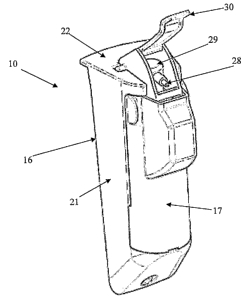
The device 10 of the illustrated embodiment includes a body portion 16
adapted to be mounted relative to a corner portion of the bin body 11 inside
the bin
body 11 and provided with removable cover means 17.
The body portion 16 of the device 10 includes a housing 19 which
together with the cover means 17, when the cover means 17 is properly mounted
to
the body portion 16) encloses the container 18 holding the material to be
dispersed.
The housing 19 of the body portion has an open interior defined by
shaped walls. There is an access opening to the interior in the body portion
at the
front of the housing 19. The exterior shape of the walls and the device in
general is
tapered from top to bottom so that the lower end of the body portion is
smaller in
cross-section than the upper portion. The purpose of the tapered external
shape of the
device is to minimise or prevent catching or engagement with a rubbish placed
in the
bin, particularly when the bin is inverted as will typically be required for
emptying.
The outer shape and configuration of the housing may not match the inner shape
of
the housing.
The housing 19 has an inner base wall 20 at a bottom portion of the
interior space so that the container 18 can rest thereon when in the housing.
The
interior space of the housing is defined by the inner base wall 20, opposed
side walls
21, an upper wall 22, and a rear wall 23.
The upper wall 22 of the housing 19 is a top wall of the body portion
and is provided with one or more openings to allow engagement with the
actuating
assembly 24 which is removable from the device 10 of the illustrated
embodiment.
In use, the upper wall 22 of the housing 19 is mounted slightly below
the upper extremity of the bin body 11. The device 10 will therefore normally
be
positioned in a corner portion adjacent the upper extremity of the bin. This
location
allows the sprayed material to be dispensed at an upper portion of the bin and
to settle
under the force of gravity once dispensed.
The device is preferably mounted in the bin utilising a mounting
arrangenzent, which in the illustrated embodiment, is located adjacent the
upper wall
22 of the body portion 19 and rearwardly of the body portion 19. According to
the
illustrated embodiment, the top wall 22 of the body portion 19 extends
rearwardly of
the rear wall 23 of the body portion 19. A depending mounting wa1125 extends
from
a rearmost outer edge of the top wall 22.
CA 02613685 2007-12-28
WO 2007/000025 PCT/AU2006/000904
The depending wall 25, the rearward extension of the top wall 22 and
the rear wall 23 of the body portion 19 define a substantially U-shaped
channel into
which a portion of a bin sidewall or the lip portion 15 is received to mount
the device.
The depending sidewall 25 also includes a securing tab to securely attach the
5 applicator relative to the bin during normal use and particularly during
emptying, but
still allow for removal if and when desired.
There is also an opening 26 provided and located adjacent the lower
end of the body portion 11 to securely fasten the lower end of the device 10
to the bin
body 11.
10 The body portion 19 of the device 10 includes a retaining strap 27 to
releasably retain the container 18 holding the material to be dispensed,
securely within
the housing.
The container 18 is a replaceable or refillable container for ease of use
and minimisation of the environmental impact of the invention. The outlet 28
of the
container 18 is associated with the depressible actuator 29 to dispense the
spray and to
draw the material from the container 18 and dispel it from the outlet 28.
The outlet 28 from the container 18 is oriented approximately
perpendicularly to the plane of the sidewalls of the bin and towards the
centre of the
bin. The material of the container 18 of the illustrated embodiment is
positively
discharged when the actuator 29 is depressed.
The device of the illustrated embodiment also includes an actuating
assembly 24 associated with the body portion 19 and mounted to be depressed
upon
closure of the bin lid 12, to engage the depressible actuator 29 of the
container 18 to
release the spray.
According to the illustrated embodiment, the actuating assembly 24
includes a shaped trigger portion 30 that directly abuts the depressible
actuator 29 of
the container 18 when the trigger 30 is depressed. A portion of the trigger 30
will be
located above the uppermost extremity of the bin body 11 when correctly
attached to
the bin and the remainder of the device 10 will be located below the uppermost
extremity of the bin body 11.
The trigger 30 is pivotally mounted on the body portion 19 of the
device 10. A central opening in the top wall 22 of the body portion 19 is
flanked on
either side with a depression into which extension portions 31 provided on the
trigger
CA 02613685 2007-12-28
WO 2007/000025 PCT/AU2006/000904
11
30 are received and about which the trigger 30 can move. The trigger 30 is
biased into
a raised position typically by biasing means provided in association with the
container
actuator 29.
There is a pair of substantially parallel, spaced apart sidewalls 32
provided on the trigger 30 to receive the actuator 29 of the container 18
therebetween
with a cross member 33 to brace the sidewalls 32 and prevent them from
deforming
inwardly or outwardly when the trigger 30 is depressed. The cross member 33
will
also function to prevent the trigger 30 depressing too far and possibly
damaging the
container 18 or the rest of the device.
In use, the device will be properly mounted in a bin. When the bin lid
12 is closed, the trigger 30 is depressed by the lid 12 and thereby depress
the actuator
29 of the container 18 with which it is associated, forcing a release of the
material into
the bin. The trigger 30 is maintained in the depressed condition until the bin
lid 12 is
lifted or removed and then is depressed again once the lid 12 is replaced.
In the present specification and claims (if any), the word "comprising"
and its derivatives including "comprises" and "comprise" include each of the
stated
integers but does not exclude the inclusion of one or more further integers.
Reference throughout this specification to "one embodiment" or "an
embodiment" means that a particular feature, structure, or characteristic
described in
connection with the embodiment is included in at least one embodiment of the
present
invention. Thus, the appearance of the phrases "in one embodiment" or "in an
embodiment" in various places throughout this specification are not
necessarily all
referring to the same embodiment. Furthermore, the particular features,
structures, or
characteristics may be combined in any suitable manner in one or more
combinations.
In compliance with the statute, the invention has been described in
language more or less specific to structural or methodical features. It is to
be
understood that the invention is not limited to specific features shown or
described
since the means herein described comprises preferred forms of putting the
invention
into effect. The invention is, therefore, claimed in any of its forms or
modifications
within the proper scope of the appended claims (if any) appropriately
interpreted by
those skilled in the art.