Note: Descriptions are shown in the official language in which they were submitted.
CA 02613845 2010-03-05
DESCRIPTION
MEMBER DESIGNING METHOD, MEMBER DESIGNING APPARATUS,
COMPUTER PROGRAM PRODUCT, AND COMPUTER-READABLE
RECORDING MEDIUM
Technical Field
[0001] The present invention relates a designing
method, a designing apparatus, a computer program
product, and a computer-readable recording medium to
design a member having superior performance in crash
absorbed energy, fatigue life, and so forth.
Background Art
[0002] In the development of vehicles such as an
automobile, in order to cope with the problems such
as weight reduction, development period reduction and
experimental vehicle manufacture reduction, in recent
years, prediction of each performance based on
numerical analysis with the use of a computer is
frequently performed in designing field.
[0003] For instance, as for a crash absorbed energy,
in order to absorb crash energy arising when the
automobile crashes, a member such as a front side
member is designed to cause a regular buckling in the
longitudinal direction thereof at the time of the
crash to absorb impact energy by plastic deformation
by the buckling, so that an occupant of the
automobile is protected.
- 1 -
CA 02613845 2007-12-28
[0004] In conventional designing of a crash energy
absorption member, after an initial shape of the
member is determined, crash analysis is performed
such as by finite element method, and a change in
shape and so forth is made to the member so that the
crash absorbed energy attains a target value. After
the evaluation by the analysis has attained the
target value, a final confirmation is made by
experimental manufacture and experiment, so that the
design is determined.
[0005] These members are manufactured by performing
plastic working to sheets, tubes or bars made of
steel or other material and, as appropriate, by
joining them. For the plastic working, a forming
method such as pressing, hydroforming, or extrusion
or the like is adopted. Also, for the joining, a
method such as spot welding, arc welding, laser
welding, or rivet connection or the like is adopted.
[0006] Conventionally, an approach referred to as
coupled analysis reaching from press forming to crash
analysis shown in Fig. 25 is known, and, in Japanese
Patent Application Laid-Open No.2004-50253 (Patent
document 1), there is disclosed a simulation
technique, in which, based on the final shape data of
a pressed part, an additional shape data is prepared
and forming analysis is performed thereafter, and
characteristic analysis such as on an ability to
withstand a crash force is performed based on the
obtained analysis result in a coupled manner. In Fig.
- 2 -
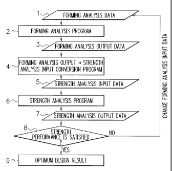
CA 02613845 2007-12-28
25, "2501" denotes an unprocessed material, "2502"
denotes the result of the forming analysis, "2503"
denotes the result of the forming analysis after
converted into input data for the crash analysis, and
"2504" denotes the result of the crash analysis.
[0007] However, in Patent document 1, no
description is given as to an approach to present an
optimum part shape and a forming condition.
[0008] It is known that, when a metal such as a
steel material is used as a material, a variation in
sheet thickness is caused due to plastic working when
manufacturing the member and/or work hardening is
caused due to the plastic strain, in which the
buckling deformation mode and/or crash absorbed
energy vari(es) when the member suffers the crash as
compared to the case where no sheet thickness
variation or working hardening is caused.
[0009] Under current condition, since neither sheet
thickness variation nor work hardening is taken into
consideration at the time of the analysis such as by
the finite element method or the like, even if the
designing is performed based on the evaluation value
obtained by the analysis, desired buckling
deformation mode and/or crash absorbed energy cannot
be obtained in the experimental manufacture or
experiment.
[0010] Further, due to a fluctuation in a plastic
working condition when manufacturing the member,
there arise(s) fluctuation(s) also in sheet thickness
3 -
CA 02613845 2007-12-28
variation and/or work hardening, finally causing the
fluctuation(s) in the buckling deformation mode
and/or crash absorbed energy.
[0011] Further, the buckling deformation mode and
the crash absorbed energy vary depending on a butt
weld line position when using a tailored blank and a
joining condition when joining a plurality of members.
[0012] Also, as for fatigue strength evaluation for
a vehicle, the development needs for an approach
allowing accurate and easy prediction of the fatigue
life of a part, a member or a structure used for the
vehicle aiming limit design are increasing more than
ever.
[0013] In this field, conventionally, static stress
analysis under the condition of a predetermined
fatigue load by the finite element method is widely
used, and when predicting the fatigue life using the
analysis result, an approach; in which an initial
shape is determined first and fatigue test data (S-N
diagram, E-N diagram) of materials previously used
for the member and of the joining portion are
obtained, predictive calculation is performed at the
same time by cross checking the diagrams, a stress
analysis value or a strain analysis value to obtain a
predictive life, and then a change is made to the
shape of the member, the material, the joining method,
or the like so that the calculated fatigue life
becomes the target value; is adopted.
[0014] After the evaluation by the analysis attains
- 4 -
CA 02613845 2007-12-28
the target value, verification is performed by
experimental manufacture and experiment to determine
a design specification. These members are
manufactured by performing plastic working to sheets,
tubes or bars made of steel or other material and, as
appropriate, by joining them. For the plastic
working, a forming method such as pressing,
hydroforming, or extrusion or the like is adopted.
Also, for the joining, a method such as spot welding,
arc welding, laser welding, or rivet connection or
the like is adopted. Recently, fatigue analysis
software automatically, which refers to a stress
calculation result file obtained by the finite
element method as well as fatigue test data of the
material previously used for the member and of the
joining portion and thereby calculates the life of
respective portions, is commercially available.
[0015] When a metal such as steel is used as a
material, due to the plastic working when forming the
member, the sheet thickness variation and plastic
strain are caused, and at the same time, when the
member is assembled, residual stress due mainly to
springback after the formation of the member is
caused, and those sheet thickness variation, plastic
strain and residual stress are known to largely
affect the member in fatigue strength. Further, the
calculation method of the residual stress when
assembling the member and the quantification method
of the fatigue strength variation due to the plastic
- 5 -
CA 02613845 2007-12-28
strain are not clearly defined, making it difficult
to build an optimization algorithm for fatigue design
of a member to obtain a forming work method
satisfying a targeted fatigue life. In the
conventional method, effects when forming and
assembling those are not taken into consideration,
and, on top of that, no optimization algorithm is
adopted, so that the fatigue design of the member
cannot be performed accurately and speedy, as a
matter of fact.
[0016) In Japanese Patent Application Laid-Open
No.2001-116664 (Patent document 2), in the analysis
method analyzing fatigue strength of a weldment
structure composed of plural members, there is
disclosed a fatigue strength analysis method
evaluating the fatigue strength, in which, based on
the shapes and welding methods of the two welded
members, in view of a weld line portion, a fatigue
strength diagram in the parallel direction to the
weld line and a fatigue strength diagram in the
vertical direction to the weld line are selected,
respectively, and with the stress analysis result of
this weldment structure, the stresses in the vertical
and parallel directions to the weld line are obtained,
and then by comparing these stresses with the fatigue
strength diagrams, respectively, to evaluate the
fatigue strength.
[0017] However, in the method disclosed in Patent
document 2, the residual stress arising at each
- 6 -
CA 02613845 2007-12-28
portion after assembling, the plastic strain given
when forming the member, and the post-formation sheet
thickness distribution are not taken into
consideration, and that, the optimization algorithm
is not adopted, leaving a problem that the fatigue
life prediction cannot be performed accurately and
speedy.
[0018] In Japanese Patent Application Laid-Open
No.2003-149091 (Patent document 3), a fatigue life
evaluation system is disclosed, in which a stress
concentration ratio corresponding to a welded shape
(finishing process) of a welded portion is recognized
beforehand for each joint type by experiment or the
like to be stored in a memory together with fatigue
life prediction data (S-N diagram) of a front
structure, stress of the welded portion is calculated
by finite element method analysis, peak stress at an
end of the portion welded by bead is calculated by
multiplying the stress value by the stress
concentration ratio corresponding to the welded shape,
and the peak stress is applied to the S-N diagram to
predict the fatigue life in accordance with the
welded shape.
[0019] In Japanese Patent Application Laid-Open
No.2003-149130 (Patent document 4), there is
disclosed a method, in which a shell model for a
finite element method analysis is prepared with
respect to a spot-welded structure composed of sheets
fitted together; and linear and elastic analysis by
7 -
CA 02613845 2007-12-28
the finite element method is performed using the
prepared shell model for the finite element method
analysis to calculate a shared load at a nugget
portion at a center of the spot welded portion as
well as a deflection on and a radial tilt angle of a
circle drawn around the nugget portion and having a
diameter of D; and then, based on the calculated
shared load and the deflection on and radial tilt
angle of the circle, nominal structural stress at the
nugget portion is obtained using the circular plate
bending theory of the elasticity theory to predict
the fatigue life of the spot-welded structure using
the nominal structural stress.
[0020] However, in the methods disclosed in Patent
documents 3 and 4, the residual stress arising at
each portion after the assembling, the plastic strain
given when the member is formed, and post-formation
sheet thickness distribution are not taken into
consideration, and that, the optimization algorithm
is not adopted, leaving a problem that the fatigue
design cannot be performed accurately and speedy.
Summary of the Invention
[0022] As has been stated, when the metal such as
steel is used as a material, the sheet thickness
variation is caused by the plastic working when
manufacturing the member and the work hardening is
caused by the plastic strain, however, at present,
the sheet thickness variation and the work hardening
- 8 -
CA 02613845 2007-12-28
are not taken into consideration at the time of the
performance analysis by the finite element method or
the like.
[0023] An object of the present invention is to
enable an optimum member designing to obtain a
desired performance including a press forming
condition while taking effects of a sheet thickness
variation and a work hardening due to a plastic
working when manufacturing a member into
consideration.
More specifically, an object of the present
invention is to enable an optimum member designing
to obtain a desired crash performance including a
press forming condition while taking effects of a
sheet thickness variation and a work hardening due to
a plastic working when manufacturing a member into
consideration.
Further, an object of the present invention is to
enable an optimum member designing including a
forming work condition to satisfy a desired fatigue
life while taking a sheet thickness variation and a
work hardening arising when forming a member as well
as a residual stress arising after assembling due
mainly to springback after the formation of the
member into consideration.
[0024] In order to attain the above-described
object, a member designing method according to the
present invention comprises: a first step where a
computer performs press forming analysis based on a
- 9 -
CA 02613845 2007-12-28
shape of a formed product or a shape of a member, a
blank holder force, a friction coefficient, a tensile
strength of a material, a yield strength, a stress-
strain relation, and a sheet thickness, as press
forming conditions, to calculate sheet thickness
distribution and post-formation strain distribution
of the formed product; and a second step where the
computer performs performance analysis based on the
sheet thickness distribution, the post-formation
strain distribution, and the shape of the formed
product or the shape of the member, as state amounts
of the formed product, to calculate performance of
the member, in which the computer repeats the
calculations performed in the process from the first
step through the second step a predetermined number
of times, with at least one of the press forming
conditions being changed, to output an optimum press
forming condition that gives a maximum value or a
target value of the performance.
Further, a member designing apparatus according
to the present invention comprises: a press forming
condition input part via which a shape of a formed
product or a shape of a member, a blank holder force,
a friction coefficient, a tensile strength of a
material, a yield strength, a stress-strain relation,
and a sheet thickness are inputted as press forming
conditions into a computer; a press forming analyzer
that performs press forming analysis based on the
shape of the formed product or the shape of the
- 10 -
CA 02613845 2007-12-28
member, the blank holder force, the friction
coefficient, the tensile strength of the material,
the yield strength, the stress-strain relation, and
the sheet thickness which are inputted via the press
forming condition input part, and calculates sheet
thickness distribution and post-formation strain
distribution of the formed product; a performance
analyzer that performs performance analysis of the
formed product based on the sheet thickness
distribution, the post-formation strain distribution,
and the shape of the formed product or the shape of
the member, as state amounts, and calculates
performance of the member; a repetitive calculation
controller that automatically executes the
calculations performed in the process from the press
forming condition input part through the performance
analyzer a predetermined number of times, with at
least one of the press forming conditions being
changed; and an optimum forming condition output part
that outputs an optimum press forming condition that
gives a maximum value or a target value of the
performance.
Still further, a computer program product
according to the present invention comprises: a
program code causing a computer to perform press
forming analysis based on a shape of a formed product
or a shape of a member, a blank holder force, a
friction coefficient, a tensile strength of a
material, a yield strength, a stress-strain relation,
- 11 -
CA 02613845 2007-12-28
and a sheet thickness, as press forming conditions,
and calculate sheet thickness distribution and post-
formation strain distribution of the formed product;
and a program code for causing the computer to
perform performance analysis of the formed product
based on the sheet thickness distribution, the post-
formation strain distribution, and the shape of the
formed product or the shape of the member, as state
amounts of the formed product, and calculate
performance of the member, in which the computer is
caused to repeat the calculations a predetermined
number of times, with at least one of the press
forming conditions being changed, and to output an
optimum press forming condition that gives a maximum
value or a target value of the performance.
Furthermore, a computer-readable recording medium
according to the present invention records a computer
program according to the present invention.
[0025] Here, a "formed product" in the present
invention is defined as a partly finished product
after press forming, and a "member" is defined as the
"formed product(s)" assembled, namely, a finished
product.
[0026] According to the present invention, an
optimum member designing to obtain a desired
performance including a press forming condition is
realized while taking effects of the sheet thickness
variation and the work hardening due to the plastic
working when manufacturing the member into
- 12 -
CA 02613845 2007-12-28
consideration.
Brief Description of the Drawings
[0027] Fig. 1 is a flowchart to explain a member
designing flow in a first embodiment;
Fig. 2 is a view showing an appearance of a
formed member;
Fig. 3 is a characteristic view showing a yield
strength / stress-strain relation of a material;
Fig. 4 is a view showing sheet thickness
distribution of a forming analysis example;
Fig. 5 is a view showing strain distribution of a
forming analysis example;
Fig. 6 is a characteristic view showing a
relation between a blank holder force and a panel
strength;
Fig. 7 is a flowchart to explain a member
designing flow in a second embodiment;
Fig. 8 is a view showing sheet thickness
distribution of a forming analysis example;
Fig. 9 is a view showing strain distribution of a
forming analysis example;
Fig. l0A is a view showing a crash analysis
example and a good buckling deformation mode;
Fig. 10B is a view showing the crash analysis
example and a bad buckling deformation mode;
Fig. 11 is a characteristic view showing a
relation between a forming condition and a crash
absorbed energy;
- 13 -
CA 02613845 2007-12-28
Fig. 12 is a characteristic view showing a
relation between a forming condition and the crash
absorbed energy;
Fig. 13 is a view showing a post-formation shape
of a tailored blank member;
Fig_ 14 is a characteristic view showing a
relation between weld line positions of the tailored
blank and the crash absorbed energy;
Fig. 15 is a view showing spot welded positions;
Fig. 16 is a characteristic view showing a
relation between joining conditions and the crash
absorbed energy;
Fig. 17A is a characteristic view showing a
relation between the yield strength / stress-strain
relation of a material for a steel plate of a tensile
strength of 270 MPa grade;
Fig. 17B is a characteristic view showing a
relation between the yield strength / stress-strain
relation of a material for a steel plate of a tensile
strength of 590 MPa grade;
Fig. 17C is a characteristic view showing a
relation between the yield strength / stress-strain
relation of a material for a steel plate of a tensile
strength of 980 MPa grade;
Fig. 18 is a flowchart to explain a member
designing flow in a third embodiment;
Fig. 19 is a view showing an example member
composed of pressed formed products;
Fig. 20 is a view showing example calculation
- 14 -
CA 02613845 2007-12-28
procedures to obtain residual stress distribution;
Fig. 21A is a view showing an example to obtain
the residual stress distribution by performing
springback analysis after assembling the formed
products into the member;
Fig. 21B is a view showing an example to obtain
the residual stress distribution by assembling the
formed products into the member after performing the
sprinback analysis to the formed products;
Fig, 22 is a characteristic view showing an
example S-N diagram with respect to prestrains;
Fig. 23 is a view showing an outline of a fatigue
strength test on a member having a hat-shape section;
Fig. 24 is a block diagram showing an example
computer system functioning as a designing apparatus;
and
Fig. 25 is a view showing an example of
conventional coupled analysis on forming process and
crash.
Detailed Description of the Preferred Embodiments
[0028] Hereinafter, preferred embodiments according
to the present invention will be described with
reference to the drawings.
<First Embodiment>
1. Design target
As an example of the present invention, an
optimum forming condition for a panel-type member
will be designed. Fig. 1 is a flowchart showing a
15 -
CA 02613845 2007-12-28
flow of a member designing method according to a
first embodiment. Fig. 2 shows an appearance of a
formed member. The panel-type member is formed by
pressing. The member receives a local force
(hereinafter called a "force") around the center
thereof and has a remaining dent after the force is
removed. A press forming condition (blank holder
force = BHF) is optimized so that the force causing a
certain amount of dent, namely a panel strength as a
performance of the member is maximized.
[0029] The panel-type member has a size of 620 mm
in one side, 70 mm in flange width, and 0.7 mm in
sheet thickness. The material is a steel plate of a
tensile strength of 370 MPa grade.
[0030] As the other press forming conditions, a
length of stroke is defined as 100 mm, an initial
blank holder force (BHF) is defined as 400 kN, a
friction coefficient is defined as 0.12, and a yield
strength / stress - strain relation of the material
is defined as shown in Fig. 3.
[0031] 2. Forming analysis
A press forming analysis is performed by
inputting the above-described press forming
conditions with the use of a finite element analysis
program PAM-STAMP. Sheet thickness distribution and
strain distribution are shown in Fig. 4 and Fig. 5,
respectively.
[0032] 3. Data conversion
The analysis result (in the case, for example, of
16 -
CA 02613845 2007-12-28
blank holder force BHF = 200 kN, the sheet thickness
= 0.613 mm and the strain = 0.07557) of the sheet
thickness and the strain by the forming analysis at a
reference position 21 shown in Fig. 2 is imported
into a spreadsheet software, and then the strain
(0.07557) is converted into the stress (375.5 MPa)
based on the stress-strain relation in Fig. 3 to be
inputted as a strength analysis condition (state
amount).
[0033] 4. Strength analysis
As a strength analysis method, a formula "Pd = K
x tm x o" (Puresu Seikei Nan-i Hando Bukku (Press
Formation Difficulty Handbook, in English, as a
reference), THE NIKKAN KOGYO SHIMBUN LTD., Tokyo,
1997) calculating the force causing the certain
amount of dent (panel strength) in the case where the
force is applied to the reference position 21 is used.
"K" indicates a constant number determined by the
panel shape, "t" indicates the sheet thickness, "m"
indicates a multiplier, and "o" indicates the stress
calculated based on Fig. 3 using the strain obtained
by the forming analysis. Here, it is assumed that K
= 1.0 and m = 2, and the strength analysis is
performed using the spreadsheet software. For
instance, when the blank holder force BHK = 200 kN,
then Pd = 1.0 x 0.613 -'x 375.5 = 141.2.
[0034] 5. Strength performance evaluation and press
forming condition change
Out of the above-described press forming
- 17 -
CA 02613845 2007-12-28
conditions, the blank holder force (BHF) is changed
within the range from 200 kN to 800 kN, and the
computer performs the calculation from the step 1 to
step 7 in Fig. 1 repeatedly four times, so that the
optimum press forming condition giving the maximum
value of the panel strength is sought.
[0035] 6. Result
The result is shown in Fig. 6. In the graph, the
horizontal axis indicates the blank holder force
(BHF) and the vertical axis indicates the panel
strength (Pd). Based on the result, the forming
condition in which the panel strength is maximized is
when the blank holder force BHF = 700 kN to 800 kN
and the panel strength is approximately 148.
[0036] <Second Embodiment>
In a second embodiment, the description will be
given of a designing of a member being a front side
member or the like of an automobile to absorb crash
energy arising at the time of an automobile crash.
[0037] Fig. 7 is a flowchart to explain the member
designing flow in the second embodiment. First, as
press forming conditions, respective conditions 71
being the shape of the member, the length of stroke,
the blank holder force, a pad pressure, the friction
coefficient, a tensile strength of the material, the
yield strength, the stress-strain relation, the sheet
thickness, and a welded position of the tailored
blank are set, and the computer performs the forming
analysis (72) by the forming analysis program using
- 18 -
CA 02613845 2007-12-28
the above conditions as input data.
[0038] Note that, in the present invention, the pad
pressure and the welded position of tailored blank
are items to be inputted as required. The tailored
blank means a material formed by welded metal plates
being different in at least any of the sheet
thickness, the tensile strength and the yield
strength in the longitudinal direction. With the pad
pressure being inputted, effects of avoiding a
failure at the time of formation such as a fracture
and wrinkle and of giving appropriate work hardening
(strain) can be expected. Further, with the input of
the welded position of tailored blank, an effect of
enhancing later-described performance at the time of
the crash obtained by arranging different sheet
thicknesses and/or material for the same members can
be expected.
[0039] Subsequently, based on the press forming
conditions 71, the computer performs the press
forming analysis (72) to convert output data (sheet
thickness distribution, strain distribution and
stress distribution) 73 of the forming analysis into
input data 75 for crash analysis by conversion
program (74).
[0040] Note that, in the present invention, the
stress distribution of the formed product is an item
to be outputted if required as a result of the
forming analysis. By outputting the stress
distribution of the formed product and by performing
- 19 -
CA 02613845 2007-12-28
the following crash analysis based thereon, an effect
of performing a highly precise designing, in which
deformation and/or destruction phenomenon(s) at the
time of the crash is (are) truly duplicated, can be
expected.
[0041] Subsequently, based on the sheet thickness
distribution, the strain distribution, the stress
distribution, the shape of the member, the joining
condition of member and an impact force of the formed
product, as crash analysis conditions 75, the
computer performs the crash analysis (76) by a crash
analysis program to output output data (crash
absorbed energy and buckling deformation mode) 77 of
the crash analysis, and evaluates them (78).
[0042] Note that, in the present invention, out of
the crash analysis conditions, the stress
distribution of the formed product is an item to be
inputted if required as described before. Also, the
joining condition of the member is the item to be
inputted into the crash analysis conditions if
required. The joining conditions are, specifically,
one kind or two kinds or more of the welding method,
a heat input, a preheat temperature, a number of spot
welding(s), a nugget diameter, the welded position,
and the like. With the joining conditions of the
member being inputted into the crash analysis
conditions, effects of making the buckling
deformation mode at the time of the crash be a
desired mode and maximizing the crash absorbed energy
- 20 -
CA 02613845 2007-12-28
can be expected.
[0043] In the crash analysis, calculations are
performed to obtain the crash absorbed energy and the
deformation mode. The deformation mode means a
deforming mode when the member receives an impact to
be deformed. Specifically, a deformation mode in
which the member is folded in an accordion manner or
a deformation mode in which the member is bent in the
middle thereof is caused.
[0044] When the crash performance does not attain
the desired value or when step 71 to step 77 are not
yet repeated predetermined number of times, at least,
one kind or more of the press forming conditions 71
or the joining condition of the member out of the
crash analysis conditions 75 is (are) changed, and
the computer performs the calculations by repeating
the step 71 to step 77 predetermined number of times.
The process stops when the crash performance attains
the desired value by repeating step 71 to step 77.
The predetermined number of times is preferably 10
times or more to seek for the maximum point of the
crash absorbed energy. Meanwhile, in order to save
the time of a series of analysis, 100 times or less
is preferable.
[0045] With this, an optimum design result 79
giving the maximum value or a stable region of the
crash absorbed energy can be obtained.
[0046] Note that the forming analysis and the crash
analysis may be performed by a commercially available
- 21 -
CA 02613845 2007-12-28
analysis program by the finite element method or the
like or a self-developed program. Also, the data
conversion from the forming analysis to the crash
analysis, the crash performance evaluation and the
change in shape and/or processing conditions are
performed by the commercially available program or
the self-developed program as well.
[0047] As stated above, the optimum member can be
designed by making the buckling deformation mode
and/or the crash absorbed energy when the automobile
crashes be the desired value(s) and by seeking for a
design point (shape of member, press forming
condition and so on) in which the crash performance
does not vary largely even if there is a fluctuation
in the processing conditions when manufacturing the
member, while taking the effects of the sheet
thickness variation and the work hardening when
manufacturing the member into consideration.
[0048] (Example 1)
1. Design target
As an example 1 of the second embodiment, optimum
forming conditions for a member formed by spot
welding a closing plate to a member having a hat-
shape section are designed. Fig. 13 shows an
appearance of the formed member. The member having
the hat-shape section is formed by pressing. The
member is assumed to be crashed around the axis in
the longitudinal direction when receiving an impact
force, and a press work condition (blank holder force
- 22 -
CA 02613845 2007-12-28
BHF) is optimized so that the crash absorbed energy
at that time is maximized.
[0049] The size of the member having the hat-shape
section is 300 mm in length, 50 mm in cross-sectional
width, 50 mm in cross-sectional height, 20 mm in
flange width and 1.4 mm in sheet thickness. The size
of the closing plate is 300 mm in length, 90 mm in
width and 1.4 mm in sheet thickness. The material is
a high-tensile steel plate of 590 MPa grade for both
the member having the hat-shape section and closing
plate.
[0050] As the other press forming conditions, the
length of stroke is defined as 50 mm, the initial
blank holder force (BHF) is defined as 40 kN, the
friction coefficient is defined as 0.15, and the
yield strength / stress - strain relation of the
material is defined as shown in Fig. 17B.
[0051] 2. Forming analysis
The above-described press forming conditions are
inputted and then the press forming analysis is
performed using a commercially available finite
element analysis program "Hyper Form" to calculate
the sheet thickness distribution shown in Fig. 8 and
the strain distribution of the formed product shown
in Fig. 9.
[0052] 3. Data conversion
The analysis result of the sheet thickness
variation and the strain distribution by the forming
analysis are converted into the input data for the
- 23 -
CA 02613845 2007-12-28
crash analysis using a self-developed FORTRAN program,
and the sheet thickness distribution, the strain
distribution and the shape of the member of the
formed product are inputted as crash analysis
conditions.
[0053] 4. Crash analysis
As a crash analysis condition, further, the
impact force equal to that in the case where a steel
of 553. 6 kg mass is crashed at a speed of 6.26 m/sec
is inputted, and the crash analysis is performed
using a commercially available finite element
analysis program "PAM-CRASH". As shown in Figs. 10A
and 10B, the crash absorbed energy and the
deformation mode are calculated including the case
where the press forming condition is changed as will
be described later. Fig. l0A shows a good buckling
deformation mode in which a regular buckling
deformation 101 is repeated in the axial direction
and Fig. 10B shows a bad buckling deformation mode in
which an irregular buckling deformation 102 is caused.
[0054] S. Crash performance evaluation and
processing condition change
A commercially available optimization tool
"iSIGHT" is used. In order to maximize and stabilize
the crash absorbed energy, out of the above-described
press forming conditions, the blank holder force
(BHF) is changed within the range from 1 kN to 350 kN,
then the computer performs calculation from the step
71 to step 77 in Fig. 7 repeatedly 70 times, and the
- 24 -
CA 02613845 2007-12-28
optimum press forming condition giving the maximum
value or the stable region of the crash absorbed
energy is sought.
[0055] 6. Result
The result is shown in Fig. 11. In the graph,
the horizontal axis indicates the blank holder force
(BHF) and the vertical axis indicates the crash
absorbed energy. Based on the result, a point 111 at
which the crash absorbed energy is maximized is when
the blank holder force BHF = 298 kN, where the crash
absorbed energy is 8044 J. However, under these
conditions, if the blank holder force BHF fluctuates,
the crash absorbed energy varies sharply, therefore,
when highly-precise press control is difficult, it is
difficult to adopt the point as the optimum design
point.
[0056] At that time, there is a range where the
blank holder force BHF = 200 kN to 250 kN as a range
112 in which the crash absorbed energy is stabilized
at higher level, so that it is found that the
midpoint thereof can be adopted as the optimum design
point.
[0057] Further, under the same conditions as of
example 1, when further performing the press forming
analysis, the stress distribution of the formed
product is calculated (view of the stress
distribution is omitted here), then the crash
analysis is performed by including this stress
distribution, and the above-described repetitive
- 25 -
CA 02613845 2007-12-28
calculations are performed 25 times while changing
the blank holder force, as a result, there exists a
range where the blank holder force BHF = 220 kN to
260 kN, so that it is found that the midpoint thereof
can be adopted as the optimum design point.
[0058] (Example 2)
1. Design target
As an example 2 of the second embodiment, optimum
forming conditions for a member formed by spot
welding the closing plate to the member having the
hat-shape section are designed. The member having
the hat-shape section is formed by pressing. The
member is assumed to be crashed around the axis in
the longitudinal direction by receiving an impact
force, and the press work condition (pad pressure) is
optimized so that the crash absorbed energy at that
time is maximized.
[0059] The size of the member having the hat-shape
section is 300 mm in length, 50 mm in cross-sectional
width, 50 mm in cross-sectional height, 20 mm in
flange width and 1.4 mm in sheet thickness. The size
of the closing plate is 300 mm in length, 90 mm in
width and 1.4 mm in sheet thickness. The material is
a high-tensile steel plate of 590 MPa grade for both
the member having the hat-shape section and closing
plate.
[0060] As the other press forming conditions, the
length of stroke is defined as 50 mm, the initial
blank holder force (BHF) is defined as 200 kN, an
- 26 -
CA 02613845 2007-12-28
initial pad pressure is defined as 1 kN, the friction
coefficient is defined as 0.15, and the yield
strength / stress - strain relation of the material
is defined as shown in Fig. 17B.
[0061] 2. Forming analysis
The above-described press forming conditions are
inputted and then the press forming analysis using
the commercially available finite element analysis
program "PAM-STAMP" is performed to calculate the
sheet thickness distribution of the formed product
similar to that shown Fig. 8 and the strain
distribution similar to that shown in Fig. 9 (drawing
is omitted here).
[0062] 3. Data conversion
The analysis result of the sheet thickness
variation and the strain distribution in the forming
analysis are converted into the input data by using
self-developed FORTRAN program, and the sheet
thickness distribution, the strain distribution and
the shape of the member for the formed product are
inputted as the crash analysis conditions.
[0063] 4. Crash analysis
As a crash analysis condition, further, the
impact force equal to that in the case where a steel
of 553. 6 kg mass is crashed at a speed of 6.26 m/sec
is inputted, and the crash analysis is performed
using the commercially available finite element
analysis program "PAM-CRASH". Including a later-
described case where the pad pressure condition is
27 -
CA 02613845 2007-12-28
changed, the same results as shown in the drawings in
Figs. 10A and 10B are obtained (drawings are omitted
here). When the pad pressure is 18 kN or more, the
buckling deformation mode such that the member is
bent is shown.
[0064] 5. Crash performance evaluation and
processing condition change
The commercially available optimization tool
"iSIGHT" is used. In order to maximize and stabilize
the crash absorbed energy, out of the above-described
press forming conditions, the pad pressure is changed
within the range from 1 kN to 25 kN, then the
computer performs calculation from the step 71 to
step 77 in Fig. 1 repeatedly 13 times, and the
optimum press forming condition giving the maximum
value or the stable region of the crash absorbed
energy is sought.
[0065] 6. Result
The result is shown in Fig. 12. In the graph,
the horizontal axis indicates the pad pressure and
the vertical axis indicates the crash absorbed energy.
Based on the result, a point 1201 at which the crash
absorbed energy is maximized is when the pad pressure
= 16 kN, where the crash absorbed energy is 8300 J.
[0066] (Example 3)
1. Design target
As an example 3 of the second embodiment, optimum
forming conditions for a member formed by spot
welding the closing plate to the member having the
- 28 -
CA 02613845 2007-12-28
hat-shape section are designed. The member having
the hat-shape section is formed by pressing a
tailored blank material. The member is assumed to be
crashed around the axis in the longitudinal direction
by receiving the impact force, and the press work
condition (weld position of the tailored blank) is
optimized so that the crash absorbed energy at that
time is maximized.
[0067] The size of the member having the hat-shape
section is 300 mm in length, 50 mm in cross-sectional
width, 50 mm in cross-sectional height, 20 mm in
flange width and 1.2 mm in sheet thickness. The size
of the closing plate is 300 mm in length, 90 mm in
width and 1.2 mm in sheet thickness. The materials
for the member having the hat-shape section are steel
plates of 270 MPa grade, 980 MPa grade and 590 MPa
grade from the above, respectively, and that for the
closing plate is a steel plate of 590 MPa grade. Fig.
13 shows an appearance of the member having the hat-
shape section.
[0068] As the other press forming conditions, the
length of stroke is defined as 50 mm, the blank
holder force (BHF) is defined as 10 kN, and the
friction coefficient is defined as 0.15. The yield /
stress - strain relations of the materials are shown
in Figs. 17A, 17B, 17C for the materials of 270 MPa
grade, 590 MPa grade, 980 MPa grade, respectively.
[0069] 2. Forming analysis
The above-described press forming conditions are
- 29 -
CA 02613845 2007-12-28
inputted and then the press forming analysis is
performed using a commercially available finite
element analysis program "Hyper-Form" to calculate
the sheet thickness distribution of the formed
product similar to that shown Fig. 8 and the strain
distribution similar to that shown in Fig. 9 (drawing
is omitted here).
[0070] 3. Data conversion
The analysis result of the sheet thickness
variation and the strain distribution by the forming
analysis are converted into the input data for the
crash analysis using the self-developed FORTRAN
program, and the sheet thickness distribution, the
strain distribution and the shape of the member of
the formed product are inputted as crash analysis
conditions.
[0071] 4. Crash analysis
As a crash analysis condition, further, the
impact force equal to that in the case where a steel
of 500 kg mass is crashed at a speed of 6 m/sec is
inputted, and the crash analysis is performed using
the commercially available finite element analysis
program "PAM-CRASH". Including a later-described
case where the weld position of the tailored blank is
changed, the same results as shown in the drawings in
Figs. 10A and 10B are obtained (drawings are omitted
here). When the weld position of the tailored blank
is "a" > 160 mm, a buckle deformation mode, in which
"c" region of 590 MPa grade steel is not folded in
- 30 -
CA 02613845 2007-12-28
good condition, is shown.
[0072] 5. Crash performance evaluation and
processing condition change
The commercially available optimization tool
"iSIGHT" is used. In order to maximize and stabilize
the crash absorbed energy, out of the above-described
press forming conditions, a weld position 1304 of the
tailored blank shown in Fig. 13 is changed within the
range from "a" = 130 mm to 170 mm, then the computer
performs calculations from the step 71 to step 77 in
Fig. 1 repeatedly 50 times, and the optimum press
forming condition giving the maximum value of the
crash absorbed energy is sought. Note that a length
1302 at a center portion is fixed to be "b" = 100 mm,
and a length 1303 at a lower portion is defined to be
"c" = (300 - a - b) mm.
[0073] 6. Result
The result is shown in Fig. 14. In the graph,
the horizontal axis indicates the weld position of
the tailored blank and the vertical axis indicates
the crash absorbed energy. Based on the result, a
point 1401 at which the crash absorbed energy is
maximized is when the weld position of the tailored
blank "a" = 148 mm, where the crash absorbed energy
is 6900 J.
[0074] (Example 4)
1. Design target
As an example 4 of the second embodiment, optimum
forming conditions for a member formed by spot
- 31 -
CA 02613845 2007-12-28
welding the closing plate to the member having the
hat-shape section are designed. The member having
the hat-shape section is formed by pressing a steel
plate. The member is assumed to be crashed around
the axis in the longitudinal direction by receiving
the impact force, and the joining condition is
optimized so that the crash absorbed energy at that
time is maximized. Specifically, as for the spot
welding of the flange of the member having the hat-
shape section and the closing plate, the number of
the weldings and the nugget diameter are optimized.
[0075] The size of the member having the hat-shape
section is 300 mm in length, 50 mm in cross-sectional
width, 50 mm in cross-sectional height, 20 mm in
flange width and 1.4 mm in sheet thickness. The size
of the closing plate is 300 mm in length, 90 mm in
width and 1.4 mm in sheet thickness. The material is
the high-tensile steel plate of 590 MPa grade.
[0076] As the other press forming conditions, the
length of stroke is defined as 50 mm, the blank
holder force (BHF) is defined as 34 kN, and the
friction coefficient is defined as 0.15. The yield
strength / stress - strain relation of the material
is defined as shown in Fig. 17B.
[0.077] 2. Forming analysis
The above-described press forming conditions are
inputted and then the press forming analysis is
performed using the commercially available finite
element analysis program "Hyper-Form" to calculate
- 32 -
CA 02613845 2007-12-28
the sheet thickness distribution of the formed
product similar to that shown Fig. 8 and the strain
distribution similar to that shown in Fig. 9 (drawing
is omitted here).
[0078] 3. Data conversion
The analysis result of the sheet thickness
distribution and the strain distribution by the
forming analysis are converted into the input data
for the crash analysis using a self-developed FORTRAN
program, and the sheet thickness distribution, the
strain distribution and the shape of the member of
the formed product are inputted as crash analysis
conditions.
[0079] 4. Crash analysis
As a crash analysis condition, further, the
impact force equal to that in the case where a steel
of 553. 6 kg mass is crashed at a speed of 6.26 m/sec
is inputted, and the crash analysis is performed
using the commercially available finite element
analysis program "PAM-CRASH Including a later-
described case where the number of welding(s) of the
spot welding and the nugget diameter are changed, the
same results as shown in the drawings in Figs. IOA
and IOB are obtained (drawings are omitted here).
When the number of the weldings of the spot welding
is seven and the nugget diameter is 7 mm, the
buckling deformation mode such that the member is
folded in an accordion manner, and when the number of
the weldings and the nugget diameter are other than
- 33 -
CA 02613845 2007-12-28
the above, the buckling deformation mode such that
the member is bent at the midpoint thereof is shown.
[0080] 5. Crash performance evaluation and
processing condition change
The commercially available optimization tool
"iSIGHT" is used. In order to maximize and stabilize
the crash absorbed energy, out of the member joining
conditions, the number of spot welding(s) is changed
within the range from 3 to 10 for one side as shown
in Fig. 15 and the nugget diameter of the spot
welding is changed within the range from 3 mm to 10
mm, and then the computer calculates the step 71 to
step 77 in Fig. 1 repeatedly 16 times, so that the
optimum press forming condition or the optimum
joining condition giving the maximum value of the
crashed absorbed energy is sought.
[0081] 6. Result
The result is shown in Fig. 16. In the graph, a
horizontal axis 1601 indicates the number of spot
weldings, a horizontal axis 1602 indicates the nugget
diameter, and a vertical axis 1603 indicates the
crash absorbed energy. Based on the result, a point
1604 at which the crash absorbed energy is maximized
is when the number of spot weldings is nine and the
nugget diameter is 10 mm, where the crash absorbed
energy is 7237 J. Further, when the number of spot
weldings is seven and the nugget diameter is 7 mm,
there is a maximum point 1605 showing a crash
absorbed energy of 7125J, and this can considered to
- 34 -
CA 02613845 2007-12-28
be a candidate of the optimum design point in
consideration of the spot welding cost.
[0082] Further, in the case where the above-
described optimum joining conditions are given, and,
as a press forming condition, the blank holder force
is changed and the above-described repetitive
calculations are performed 13 times, the crash
absorbed energy is stabilized at high level when the
blank holder force BHF = 200 kN to 250 kN, and it is
found that the middle point thereof can be adopted as
the optimum design point.
[0083] <Third embodiment>
In a third embodiment, a part, a member or a
structure used in a vehicle, especially an industrial
vehicle such as an automobile, an agricultural
vehicle and the like is predicted in view of fatigue
life against cyclic load arising when driving the
vehicle, and a designing of optimum press forming
conditions giving a maximum value of the fatigue life
or a target fatigue life will be described.
[0084] With reference to the flowchart in Fig. 18,
a member designing flow according to the third
embodiment will be described. First, as the press
forming conditions, respective input data 1801 being
the shape of a material before forming, the shape of
the formed product, a tool shape, the length of
stroke, the blank holder force, the friction
coefficient, the tensile strength of the material,
the yield strength, the stress-strain relation and
- 35 -
CA 02613845 2007-12-28
sheet thickness are set, and the computer performs
the press forming analysis (1802) by the forming
analysis program using the above conditions as input
data.
[0085] Based on the input data 1801 of the press
forming conditions, the computer performs the press
forming analysis (1802), and outputs the sheet
thickness, the post-formation stress distribution and
the post-formation strain distribution of the formed
product as output data 1803 of the press forming
analysis.
[0086] Subsequently, the sheet thickness
distribution, the post-formation stress distribution
and the shape of the member out of the output data
1803 of the press forming analysis are set as input
data 1804 of the springback analysis conditions, and
the computer performs the springback analysis (1806)
using the springback analysis program based on the
input data 1804 to.output a residual stress
distribution of the member as output data 1808 of the
springback analysis.
[0087] Also, in parallel therewith, out of the
output data 1803 of the press forming analysis, the
sheet thickness distribution, the shape of the member,
and the static load are set as input data 1805 for
the elastic analysis conditions, and the computer
performs the elastic analysis (1807) on the member
based on the input data 1805 using an elastic
analysis program to output the post-elastic formation
- 36 -
CA 02613845 2007-12-28
stress distribution and the post-elastic deformation
strain distribution as output data 1809 of the
elastic analysis.
[0088] Subsequently, the post-formation strain
distribution out of the output data 1803 of the press
forming analysis, a residual stress distribution of
the output data 1808 of the springback analysis, and
the post-elastic deformation stress distribution and
the post-elastic deformation strain distribution out
of the output data 1809 of the elastic analysis, and
a fatigue load are set as condition input data 1810
for a fatigue analysis, and the computer performs the
fatigue analysis (1811) based on the input data 1810
using the fatigue analysis program to output the
fatigue life of the member as output data 1812 of the
fatigue analysis and evaluate whether or not the
fatigue life satisfies the target life or whether or
not the fatigue life is the maximum value (1813).
[0089] When the fatigue life of the member does not
attain a desired value, at least one kind or more of
the input data 1801 of the press forming conditions
is/are changed and the computer calculates again from
step 1801 to step 1812 repeatedly a predetermined
number of times.
[0090] When the fatigue life of the member has
attained the desired value by repeating step 1801 to
step 1812, the process is stopped.
[0091] With this, it is possible to obtain the
optimum press forming conditions 1814 giving the
- 37 -
CA 02613845 2007-12-28
maximum value of the fatigue life or the target life.
[0092] Note that for the press forming analysis,
the springback analysis, the static elastic analysis
and the fatigue life analysis, a commercially
available analysis program by the finite element
method or the like or a self-developed program can be
used. As a press forming analysis program or a
springback analysis program, there are commercially
available solvers such as the PAM-STAMP, a LS-DYNA,
an ABAQUS and the like, and as those for the elastic
analysis, there are commercially available solvers
using the finite element method such as a NASTRAN, a
MARC, the ABAQUS and the like. As a fatigue life
analysis program, there is commercially available
software such as a MSC. Fatigue, a FEMFAT, a FE-
Fatigue or the like. Further, the data transfer
to/from the press forming analysis result or the
springback analysis result to/from the fatigue life
analysis, and an analysis condition change are
performed using a commercially available program or a
self-developed program. As an optimization tool
automatically changing the analysis condition and
performing repetitive calculation to obtain the
optimum result, commercially available optimization
software iSIGHT, OPTIMUS, AMDESS and the like are
prepared, so that the repetitive calculation shown in
Fig. 18 can be automated.
[0093] The input data 1804, 1805, 1810 may be
inputted from an external input part in each case or
- 38 -
CA 02613845 2007-12-28
may be imported automatically in the program.
[0094] Fig. 19 shows an example member formed by
two press formed products 1901, 1902 assembled by
spot weldings 1903. Further, in Fig. 20, example
calculation procedures (corresponding to 1801, 1802,
1803, 1804, 1806, 1808 in Fig. 18) to obtain the
residual stress distribution of the member, in which
the press forming analysis of the formed product and
the springback analysis of the member are performed,
are shown. Based on shape data 2004 of the material
before forming and shape data of tools (punch mold
2005, die mold 2006), a finite element mesh model
2007 is generated, and a press forming analysis 2008
is performed based on the press forming conditions to
obtain the sheet thickness distribution at a dead
point after formed, the post-formation stress
distribution and the post-formation strain
distribution.
[0095] Using the formed product, in which the sheet
thickness distribution and the post-formation stress
distribution obtained in the press forming analysis
2008 are mapped, member assembling 2009 is performed
on the computer and then springback analysis 2010 is
performed, so that the residual stress distribution
of the member is obtained. As for the calculation of
the residual stress distribution, it is possible to
obtain the residual stress generated at a jointed
portion or a metal material portion, after performing
the springback analysis on the formed product,
- 39 -
CA 02613845 2007-12-28
jointing the formed products on the computer, and
assembling the member.
[0096] Figs. 21A and 21B show two types of the
above-described processes in which the formed
products are assembled to obtain the residual stress.
Fig. 21A shows an example, in which two formed
products 2101 each having the hat-shape section are
assembled into a member by a spot welding 2103 to
obtain the residual stress distribution by performing
the springback analysis, and Fig. 21B shows an
example, in which the springback analysis is
performed on the formed products each having the hat-
shape section, displacement distributions by the
springback are calculated, deformed shapes of the
formed products are obtained, and they are assembled
into the member based on the deformed shapes by a
spot welding 2102 to obtain the residual stress
distribution.
[0097] Subsequently, an example fatigue life
calculation considering the post-formation strain
distribution and performed in the fatigue life
analysis program 1811 will be shown. The post-
formation strain distribution obtained by the press
forming analysis is set as the prestrain distribution
of the member and the S-N diagram and the E-N diagram
are selected based on the value to perform the
fatigue life calculation. Here, the E-N diagram
indicates the fatigue life diagram showing a relation
between the strain value and the number of cycles.
- 40 -
CA 02613845 2007-12-28
For the S-N diagram and E-N diagram, it is possible
to use commercially available data or data in
publicly known document, and it is also possible to
use the data prepared by performing the fatigue test
in advance using the same steel material as used in
the designing. Generally, the fatigue strength of
the metal material that has experienced prestrain
increases in a high cycle region.
[0098] Fig. 22 is an S-N diagram showing an effect
of the prestrain with respect to a steel material,
which can be obtained by giving a predetermined
strain to a fatigue test specimen in advance, and
performing the fatigue test. As an example, at a
position of a node point (node) in the finite element
mesh model of the member, a prestrain of 30% is given
and a fatigue load is added as well, and when the
stress of 350 MPa arises at the node point, as shown
by a dotted arrow in the drawing, the S-N line of the
prestrain of 30% is selected, and the estimated
fatigue life (number of cycles) at the node point can
be calculated to be 800 thousand times. By the
similar calculation method, the fatigue life is
calculated for every node point in the finite element
mesh model of the member, and out of the calculation
results, the minimum value is defined as a predicted
fatigue life.
[0099] As has been described, the residual stress
generated at respective portions after assembling,
the plastic strain arising when forming the member,
41 -
CA 02613845 2007-12-28
and the sheet thickness variation are taken into
consideration, while the press forming conditions
making the fatigue life under the fatigue load
conditions in compliance with the practical use
environment of the member be the desired value is
obtained in an accurate and speedy manner, so that
the optimum member can be designed.
[0100] (Example)
1. Design target
As an example of the third embodiment, optimum
press forming conditions for a member having a hat-
shape section formed by spot welding a closing plate
2302 to a flange portion of a formed product 2301
having a hat-shape section as shown in Fig. 23 are
designed. A fixing-side closing plate 2304 is
completely fixed to the member having the hat-shape
section by which the member having the hat-shape
section is placed in a cantilever state, and a
torsional fatigue load is repeatedly added around the
long axis to obtain the optimum press forming
condition (blank holder force) in which the fatigue
life (number of cycles) is maximized. The cyclic
fatigue load is a fatigue load 2305 of completely
reversed torsion, being 400 Nm.
[0101] The size of the member having the hat-shape
section 2301 is 300 mm in length, 120 mm in cross-
sectional width, 70 mm in cross-sectional height, 20
mm in flange width and 1.4 mm in sheet thickness.
The size of a closing plate 2303 is 160 mm in width,
- 42 -
CA 02613845 2007-12-28
300 mm in length and 1.4 mm in sheet thickness. The
size of the force-applied-side closing plate 2303 and
the fixing-side closing plate 2304 is 200 mm in width,
200 mm in length and 5.0 mm in sheet thickness,
respectively. As for the size of the tools, the
shape size of the punch mold and die mold are set
based on the shape size of the formed product 2301
having the hat-shape section. The size of the
material before forming is 300 mm in width, 300 mm in
length and 1.4 mm in sheet thickness.
[0102] As the other press forming conditions, the
length of stroke is defined as 70 mm, the initial
blank holder force (BHF) is defined as 10 kN, and the
friction coefficient is defined as 0.15. The yield
strength of the material is 340 MPa, the stress-
strain relation
(Y = 900 x (s + 0.0006) 0.17
Here, 6 is an actual stress and "s " is an
actual strain.
[0103] 2. Press forming analysis
The above-described press forming conditions are
inputted and the press forming analysis is performed
on the formed product 2301 having the hat-shape
section using the commercially available finite
element method program ABAQUS to thereby calculate
the sheet thickness, the post-formation stress
distribution and the post-formation strain
distribution of the formed product.
[0104] 3. Springback analysis
- 43 -
CA 02613845 2007-12-28
The formed product 2301 having the hat-shape
section and the closing plate 2302 are assembled on
the computer into the member having the hat-shape
section, and the springback analysis is performed
based on the sheet thickness, the post-formation
stress distribution and the post-formation strain
distribution of the formed product 2301 having the
hat-shape section as the springback analysis
conditions by using the commercially available finite
element method program ABAQUS, so that the residual
stress of the member is calculated.
[0105] 4. Elastic analysis
The formed product 2301 having the hat-shape
section, the closing plate 2302, the force-applied-
side closing plate 2303 and the fixing-side closing
plate 2304 are assembled on the computer into the
member having the hat-shape section, and after that,
the elastic analysis is performed based on the sheet
thickness distribution of the formed product 2301
having the hat-shape section, the shape of the member
and a torsional force 400 Nm as elastic analysis
conditions using a commercially available finite
element method program NASTRAN, so that the post-
elastic deformation stress distribution and the post-
elastic deformation strain distribution of the member
are calculated.
[0106] 5. Fatigue analysis
The fatigue life (number of cycles) of the member
having the hat-shape section when the torsional
- 44 -
CA 02613845 2007-12-28
fatigue load is applied is.calculated based on the
post-formation strain distribution of the formed
product 2301 having the hat-shape section calculated
in the press forming analysis, the residual stress
distribution of the member having the hat-shape
section calculated in the springback analysis, the
post-elastic formation stress distribution and the
post-elastic deformation strain distribution of the
member having the hat-shape section calculated in the
elastic analysis, and the torsional force, as fatigue
analysis conditions using a commercially available
fatigue analysis program FE-Fatigue. Note that the
S-N diagram for spot welding stored in the
commercially available fatigue analysis software FE-
Fatigue is used for the S-N data at the spot-welded
portion, and the S-N diagram shown in Fig. 22 is used
for the S-N data of the metal material portion of the
member.
[0107] 6. Press forming condition change
For the optimization tool, the commercially
available iSIGHT is used, in which the blank holder
force is changed within the range from 10 kN to 350
kN, and the computer performs the step 1801 to step
1812 in Fig. 18 repeatedly 70 times, so that the
optimum press design conditions maximizing the
fatigue life is sought.
[0108] 7. Result
As to the relation between the fatigue life and
the blank holder force, too small blank holder force
- 45 -
CA 02613845 2007-12-28
leads to large springback, in which the residual
stress affecting the metal material portion and the
spot welded portion of the structure is large, so
that the fatigue life falls. Meanwhile, excessively
large blank holder force leads to large reduction in
the sheet thickness of the member, in which torsional
rigidity (secondary moment of the section) falls to
increase the stress generated at the metal material
portion and/or the spot-welded potion, having a
tendency to reduce the fatigue life. Further, an
increase in the blank holder force causes a tension
fracture at the time of the press formation, making
the formation sometimes be impossible.
[0109] As a result of the search for the optimum
press forming conditions by performing repetitive
calculations in accordance with the fatigue designing
method according to the present invention, it is
found that the blank holder force is 200 kN and the
maximum fatigue life (number of cycles) is 850
thousand times. The member is manufactured based on
the press formed product press formed under this
condition, and when the fatigue test is performed
under the conditions: a cyclic fatigue load being the
force under completely reversed torsion is 400 Nm,
and a frequency of cyclic load is 5 Hz, using a
hydraulic-servo fatigue testing machine exhibiting a
maximum force of 10 kN, it is confirmed that, at the
time when the number of cycles reaches to 1050
thousand times, a first crack is generated at the
46 -
CA 02613845 2007-12-28
spot welded portion at the center potion, allowing
the fatigue life over the target to be obtained.
[0110] Fig. 24 is a block diagram showing an
example computer system serving as a designing
apparatus capable of realizing the designing method
of the above-described respective embodiments. In
the drawing, "2400" denotes a computer PC. The PC
2004 includes a CPU 2401 and executes device control
software recorded in a ROM 2402 or a hard disk (HD)
2411 or supplied from a flexible disk drive (FD) 2412
to comprehensively control the respective devices
connected to a system bus 2404.
[0111] The respective functional means of the
present embodiment are composed of the programs
recorded in the CPU 2401, the ROM 2402 or the hard
disk (HD) 2411 of the above-described PC 2400.
[0112] "2403" denotes a RAM and serves as a main
memory of the CPU 2401, a work area, and so on.
"2405" denotes a key board controller (KBC)
controlling to input signals inputted from a key
board (KB) 2409 into the system itself. "2406"
denotes a display controller (CRTC) controlling a
display on a display device (CRT) 2410. "2407"
denotes a disk controller (DKC) controlling access to
a boot program (activation program: starts executing
(operating) hardware or software in a personal
computer), the hard disk (HD) 2411 recording a
plurality of application, edit file, user file,
network management program and so forth, and the
- 47
CA 02613845 2007-12-28
flexible disk (FD) 2412.
[0113] "2408" denotes a network interface card
(NIC) receiving and sending data interactively with a
network printer, other network equipment or other
personal computer via a LAN 2420.
[0114] Note that the present invention is
applicable to both a system composed of plural
equipment and a device composed of single equipment.
[0115] Further, not to mention, the object of the
present invention can be achieved by supplying a
recording medium, in which program code of software
realizing the function of the above-described
embodiments is recorded, to a system or a device and
by reading out and executing the program code stored
in the recording medium by the computer (CPU or MPU)
of the system or the device.
[0116] In this case, the program code read out from
the recording medium itself is to realize the
functions of the above-described embodiments, so that
the recording medium recording the program code
composes the present invention. As a recording
medium to supply the program code, for example, a
flexible disk, a hard disk, an optical disk, a
magnetic optical disk, a CD-ROM, a CD-R, a magnetic
tape, an involatile memory card, a ROM, and the like
can be used.
[0117] In the above, the present invention has been
described together with various embodiments, however,
the present invention is not limited only to these
- 48 -
CA 02613845 2007-12-28
embodiments and can be changed and so forth within
the scope of the present invention.
Industrial Applicability
[0118] According to the present invention, an
optimum member designing to obtain a desired
performance including a press forming condition is
realized while taking effects of a sheet thickness
variation and a work hardening due to a plastic
working when manufacturing a member into
consideration.
- 49 -