Note: Descriptions are shown in the official language in which they were submitted.
CA 02613931 2007-12-07
On-Demand Water Heater Utilizing Medium from a Pulsed Electrolysis System and
Method of
Using Same
FIELD OF THE INVENTION
The present invention relates generally to water heating systems.
BACKGROUND OF THE INVENTION
Water heaters are known in the art. One type of water heater, referred to as
an
instantaneous, flow-through, tankless or on-demand water heater, heats only
the amount of water
required by the end user. In such a water heater, when the end user opens a
hot water tap, the water
heater senses the demand and heats the water using a burner or heating element
for as long as the demand
continues. The amount of heat applied to the water passing through the water
heater can be fixed or
variable. In a fixed-capacity system, a constant amount of heat is provided by
the heating
element/burner. As a result of this configuration, as the demand increases the
water temperature drops.
In a variable-capacity system, the amount of heat provided by the heating
element/bumer is varied by the
system controller, thus allowing more heat to be applied when the demand
increases, and less heat when
the demand decreases, thereby providing the same output temperature regardless
of the demand.
Although instantaneous water heaters cost more due to their complexity,
typically they are much more
efficient than a standard storage water heater.
Regardless of whether a water heater uses a gas flame or a resistive element
as the heat
source, ultimately the energy required to fuel the heater is a conventional
fossil fuel since few regions in
the world rely on altemative energy sources. As such, water heaters contribute
to the world's
dependence on fossil fuels, an energy source of finite size and limited
regional availability. Dependence
on fossil fuels not only leads to increased vulnerability to potential supply
disruption, but also continued
global warming due to carbon dioxide emissions.
Within recent years there has been considerable research in the area of
alternative fuels
that provide a`green' approach to the development of electricity. Clearly the
benefit of such an
approach, besides combating global warming and lessening the world's
dependence on fossil fuels, is
that the energy provided by the alternative source can then be used to power a
host of conventional
electrically power~d devices without requiring any device modification.
Unfortunately, until such an
alternative source is accepted and tied in to the existing power grid, there
is little for the end consumer to
do to lessen their contribution to the world's dependence on fossil fuels
other than to simply lessen their
I
CA 02613931 2007-12-07
overall power consumption. To date, such an approach has had limited success
with most people
refusing to limit their power consumption.
Accordingly, what is needed is a means of helping end users to lower their
power
consumption without requiring actual sacrifice. The present invention, by
providing a high efficiency
on-demand water heater utilizing an alternative heat source, provides such a
system.
SUMMARY OF THE INVENTION
The present invention provides an on-demand water heater and a method of
operating
the same, the water heater including an electrolytic heating subsystem. The
electrolytic heating
subsystem is a pulsed electrolysis system that heats the medium contained
within the electrolysis tank.
The medium is pumped out of the electrolysis tank, through a conduit, and then
back into the electrolysis
tank. As the medium is circulated through the conduit, it heats an integrated
heating element. When
water passes through the on-demand water heater, in response to user demand,
the water passes through a
heat exchange conduit integrated within the water pipe and positioned in close
proximity to the heating
element. As the water passes through the heat exchange conduit, it becomes
heated. In at least one
embodiment, the system is configured to allow cold water to be mixed with the
hot water, thus providing
an additional level of temperature control.
In one embodiment of the invention, the on-demand water heater includes an
electrolytic
heating subsystem comprised of an electrolysis tank, a membrane separating the
electrolysis tank into
two regions, at least one pair of low voltage electrodes, at least one pair of
high voltage electrodes, a low
voltage source, a high voltage source, and means for simultaneously pulsing
both the low voltage source
and the high voltage source. Coupled to the electrolysis tank is a circulation
conduit which includes an
integrated heating element, the circulation conduit coupled to a circulation
pump. In close proximity to
the heating element is a heat exchange conduit that is integrated into a hot
water supply pipe. As water
passes through the hot water supply pipe, in response to user demand, the
water becomes heated as it
passes through the heat exchange conduit. The water heater can also include a
system controller that can
be coupled to one or more temperature monitors, the low and high voltage
sources, the pulse generator,
the circulation pump, a water level monitor, flow valves and/or a pH or
resistivity monitor. The water
heater can also include a thermally insulated housing, the housing preferably
surrounding at least the
heating element and the heat exchange conduit. The water heater can also
include means, such as a
variable flow valve, for mixing cold water into the heated water in order to
achieve the desired water
temperature. The water heater can further be comprised of at least one
electromagnetic coil capable of
generating a magnetic field within a portion of the electrolysis tank. The
water heater can further be
2
CA 02613931 2007-12-07
comprised of at least one permanent magnet capable of generating a magnetic
field within a portion of
the electrolysis tank.
In another embodiment of the invention, the on-demand water heater includes an
electrolytic heating subsystem comprised of an electrolysis tank, a membrane
separating the electrolysis
tank into two regions, at least one pair of high voltage electrodes, a
plurality of metal members contained
within the electrolysis tank and interposed between the high voltage
electrodes and the membrane, a high
voltage source, and means for pulsing the high voltage source. Coupled to the
electrolysis tank is a
circulation conduit which includes an integrated heating element, the
circulation conduit coupled to a
circulation pump. In close proximity to the heating element is a heat exchange
conduit that is integrated
into a hot water supply pipe. As water passes through the hot water supply
pipe, in response to user
demand, the water becomes heated as it passes through the heat exchange
conduit. The water heater can
also include a system controller that can be coupled to one or more
temperature monitors, the high
voltage source, the pulse generator, the circulation pump, a water level
monitor, flow valves and/or a pH
or resistivity monitor. The water heater can also include a thermally
insulated housing, the housing
preferably surrounding at least the heating element and the heat exchange
conduit. The water heater can
also include means, such as a variable flow valve, for mixing cold water into
the heated water in order to
achieve the desired water temperature. The water heater can further be
comprised of at least one
electromagnetic coil capable of generating a magnetic field within a portion
of the electrolysis tank. The
water heater can further be comprised of at least one permanent magnet capable
of generating a magnetic
field within a portion of the electrolysis tank.
]In another aspect of the invention, a method of operating an on-demand water
heater is
provided, the method comprising the steps of heating a liquid contained within
an electrolysis tank using
an electrolytic heating subsystem, circulating the heated liquid through a
circulation conduit and a
heating element integrated within the circulation conduit, passing water
through a heat exchange conduit
integrated within a water pipe in response to a demand for hot water, wherein
the heat exchange conduit
is proximate the heating element, heating the water as it passes through the
heat exchange conduit, and
suspending the step of passing water through the heat exchange conduit when
the demand for hot water
is terminated. In at least one embodiment, the method further comprises the
steps of measuring the
temperature of the water after it has passed through the heat exchange
conduit, comparing the measured
temperature to a preset temperature, and mixing cold water with the hot water
if the measured
temperature is above the preset temperature. In at least one other embodiment,
the method further
comprises the steps of periodically measuring the temperature of the
electrolysis liquid, comparing the
measured temperature with a preset temperature or temperature range, and
modifying at least one process
3
CA 02613931 2007-12-07
parameter of the electrolytic heating subsystem if the measured temperature is
outside (lower or higher)
of the preset temperature or temperature range. In at least one embodiment,
the step of heating the liquid
contained within the electrolysis tank using an electrolytic heating subsystem
further comprises the steps
of applying a low voltage to at least one pair of low voltage electrodes
contained within the electrolysis
tank of the electrolytic heating subsystem and applying a high voltage to at
least one pair of high voltage
electrodes contained within the electrolysis tank, wherein the low voltage and
the high voltage are
simultaneously pulsed. In at least one embodiment, the step of heating the
liquid contained within the
electrolysis tank using an electrolytic heating subsystem further comprises
the steps of applying a high
voltage to at least one pair of high voltage electrodes contained within the
electrolysis tank, the high
voltage applying step further comprising the step of pulsing said high
voltage, wherein at least one metal
member is positioned between the high voltage anode(s) and the tank membrane
and at least one other
metal member is positioned between the high voltage cathode(s) and the tank
membrane. In at least one
embodiment, the method further comprises the step of generating a magnetic
field within a portion of the
electrolysis tank, wherein the magnetic field affects a heating rate
corresponding to the liquid heating
step.
A further understanding of the nature and advantages of the present invention
may be
realized by reference to the remaining portions of the specification and the
drawings.
BRIEF DESCRIPTION OF THE DRAWINGS
Fig. 1 is an illustration of an exemplary embodiment of the invention;
Fig. 2 is an illustration of an alternate exemplary embodiment providing
additional
control of the output water temperature via cold water mixing;
Fig. 3 illustrates an exemplary embodiment in which the medium contained
within the
electrolysis tank of the electrolytic heating subsystem is circulated through
the heating element of the on-
demand water heater;
Fig. 4 is a detailed view of an embodiment of the electrolytic heating
subsystem;
Fig. 5 is a detailed view of an alternate embodiment of the electrolytic
heating subsystem
shown in Fig. 4;
Fig. 6 is a detailed view of an alternate embodiment of the electrolytic
heating subsystem
shown in Fig. 4 utilizing an electromagnetic rate controller;
Fig. 7 is a detailed view of an alternate embodiment of the electrolytic
heating subsystem
shown in Fig. 5 utilizing an electromagnetic rate controller as shown in Fig.
6;
Fig. 8 is a detailed view of an alternate embodiment of the electrolytic
heating subsystem
shown in Fig. 6 utilizing a permanent magnet rate controller;
4
CA 02613931 2007-12-07
Fig. 9 is a detailed view of an alternate embodiment of the electrolytic
heating subsystem
shown in Fig. 7 utilizing a permanent magnet rate controller;
Fig. 10 illustrates one method of operating the on-demand water heater of the
invention;
Fig. 11 illustrates an alternate method of system operation;
Fig. 12 illustrates another alternate method of system operation;
Fig. 13 illustrates another alternate method of system operation; and
Fig. 14 illustrates another alternate method of system operation.
DESCRIPTION OF THE SPECIFIC EMBODIMENTS
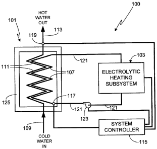
Fig. I is an illustration of an exemplary system 100 in accordance with the
invention.
System 100 is comprised of two primary subsystems; on-demand water heater 101
and a pulsed
electrolytic heating subsystem 103. As will be described in detail, there are
numerous configurations of
electrolytic heating subsystem 103 applicable to the invention.
In operation, electrolytic heating subsystem 103 maintains the fluid within
the
electrolysis tank and within heating element 107 at a relatively high
temperature, typically on the order
of at least 40 - 50 C, more preferably on the order of 60 - 75 C, and
still more preferably on the order
of 75 - 95 C. It some embodiments, even higher temperatures are used, for
example on the order of
100 - 150 C, or on the order of 150 - 250 C, or on the order of 250 - 350
C. Depending upon the
desired operating temperature and the characteristics of the electrolysis
medium, subsystem 103, heating
element 107 and the coupling conduits can all be designed to operate at high
pressures, typically at least
high enough to prevent medium boiling.
In use, when a demand is placed on the system to supply hot water, for example
when
the end-user turns on the hot water tap, cold water enters through pipe 109,
passes through heat exchange
conduit 111, and exits via pipe 113. Although there are a variety of designs
that can be used both for
heating element 107 and heat exchange conduit 111, in general the intent is to
maximize heat transfer
from element 107, which contains the heated electrolysis medium, to the water
contained within conduit
111. Accordingly, heat exchange conduit 111 and heating element 107 are
preferably positioned in close
proximity to one another, for example intertwined together, and may also
include protrusions (e.g.,
interleaved fins) to augment heat transfer.
In a preferred embodiment of the invention, a system controller 115 controls
the
performance of the system, preferably by varying one or more operating
parameters (i.e., process
parameters) of electrolytic heating subsystem 103 to which it is attached.
Varying operating parameters
of subsystem 103, for example cycling the subsystem on and off or varying
other operational parameters
as described further below, allows the steady state temperature of the
subsystem and heating element 107
5
CA 02613931 2007-12-07
to be maintained at the desired temperature. A temperature monitor 117,
coupled to the heating element
107, allows controller to obtain feedback from the system as the operational
parameters are varied.
Preferably a second temperature monitor 119, coupled to water pipe 113,
monitors the temperature of the
output water to insure that the system is operating as desired. Note that in
the illustrated configuration
in which the electrolysis medium is circulated through conduits 121 by
circulation pump 123, preferably
pump 123 is also connected to controller 115.
In at least one embodiment of the invention, heating element 107 and heat
exchange
conduit 111 are contained within a housing 125. In order to maximize system
efficiency while
minimizing the risks (e.g., fire hazard) associated with incorporating the
system into a commercial or
residential structure, preferably electrolytic heating subsystem 103, housing
125, and the conduits that
couple subsystem 103 to heating element 107, are all thermally insulated. As
heating element 107 is
maintained at an elevated temperature in order to provide the desired
instantaneous heating, in effect
thermally insulated housing 125 creates a high temperature oven through which
the water pipe, and in
particular heat exchange conduit 111, run.
Although system 100 can be operated as a fixed-capacity system, i.e., a system
which
imparts the same amount of heat to the water flowing through the system
regardless of the volume of
water, preferably it operates as a variable-capacity system. Such a variable-
capacity system can be
achieved by varying the output of electrolytic heating subsystem 103 via
control of its operating
parameters and/or by controlling the flow of electrolysis medium flowing
through conduits 121 and
heating element 107 (i.e., by utilizing a flow valve or regulating the output
of circulation pump 123).
Alternately and as illustrated in Fig. 2, the invention can be implemented as
a variable-
capacity system by coupling a cold water pipe 201 to hot water output pipe
113. By regulating the
amount of cold water entering hot water pipe 113, the temperature of the hot
water exiting the overall
system can be controlled even though the flow rate, driven by user demand, is
varying. Preferably in
such an embodiment the temperature of the water is monitored both before
(e.g., monitor 119) and after
(e.g., monitor 203) the point at which cold water pipe 201 is coupled to hot
water pipe 113. A variable
flow valve 205 or other means is used to control the flow of cold water into
hot water pipe 113, flow
valve 205 preferably under the control of system controller 115. In at least
one embodiment of the
invention, output water temperature control is achieved by a combination of
controlling the output of the
electrolytic heating subsystem and/or the flow of electrolysis medium through
heating element 107
and/or the amount of cold water mixed into the hot water through secondary
water input pipe 201.
Fig. 3 illustrates the prefen:ed means used to remove heat from electrolytic
heating
subsystem 103 in order to heat the water that passes from cold water inlet 109
to hot water outlet 113. It
6
CA 02613931 2007-12-07
should be understood that although these features are illustrated relative to
system 200, they are equally
applicable to system 100.
In the embodiment illustrated in Fig. 3, medium 301 contained within
electrolysis tank
303 is circulated through conduit 121 to heating element 107. During operation
of electrolytic heating
subsystem 103, medium 301 is heated and pumped through conduit 121 and heating
element 107,
thereby heating the water passing through pipes 109/113 and heat exchange
conduit 111.
Particulars of the electrolytic heating subsystem will now be provided. Fig. 4
is an
illustration of a preferred embodiment of an electrolytic heating subsystem
400. Note that in Figs. 4-9
only a portion of conduits 121 are shown. Additionally, while Fig. 3 only
shows a single pair of conduits
121 for tank 303, preferably each region of the electrolysis tank includes an
inlet and an outlet conduit
121 as shown in Fig. 4, thus insuring that the electrolysis medium circulated
through the heating element
is coupled to both regions.
If desired, the flow of electrolysis medium flowing through conduit 121 can be
controlled through the inclusion of one or more valves. In the embodiment
shown in Fig. 4, each of the
conduits 121 coupled to the two regions of the electrolysis tank 401 include a
control valve 403, although
it will be appreciated that the system can operate with fewer valves. Control
valve or valves 403 are
preferably coupled to controller 115 as shown.
Tank 401 is comprised of a non-conductive material. The size of tank 401 is
primarily
selected on the basis of desired system output, i.e., the level of desired
heat, which at least in part is
based on the expected flow rates for the on-demand heater 101. Although tank
401 is shown as having a
rectangular shape, it will be appreciated that the invention is not so limited
and that tank 401 can utilize
other shapes, for example cylindrical, square, irregularly-shaped, etc. Tank
401 is substantially filled
with medium 405. In at least one preferred embodiment, liquid 405 is comprised
of water, or more
preferably water with an electrolyte, the electrolyte being an acid
electrolyte, a base electrolyte, or a
combination of an acid electrolyte and a base electrolyte. Exemplary
electrolytes include potassium
hydroxide and sodium hydroxide. The term "water" as used herein refers to
water (H20), deuterated
water (deuterium oxide or D20), tritiated water (tritium oxide or T20),
semiheavy water (HDO), heavy
oxygen water (H2 180 or HZ"O) or any other water containing an isotope of
either hydrogen or oxygen,
either singly or in any combination thereof (for example, a combination of H20
and DZO).
A typical electrolysis system used to decompose water into hydrogen and oxygen
gases
utilizes relatively high concentrations of electrolyte. Subsystem 103,
however, has been found to work
best with relatively low electrolyte concentrations, thereby maintaining a
relatively high initial water
resistivity. Preferably the water resistivity prior to the addition of an
electrolyte is on the order of 1 to 28
7
CA 02613931 2007-12-07
megohms. Preferably the concentration of electrolyte is in the range of 0.05
percent to 10 percent by
weight, more preferably the concentration of electrolyte is in the range of
0.05 percent to 2.0 percent by
weight, and still more preferably the concentration of electrolyte is in the
range of 0.1 percent to 0.5
percent by weight.
Separating tank 401 into two regions is a membrane 407. Membrane 407 permits
ion/electron exchange between the two regions of tank 401. Assuming medium 405
is water, as
preferred, small amounts of hydrogen and oxygen are produced during operation.
Accordingly
membrane 407 also keeps the oxygen and hydrogen bubbles produced during
electrolysis separate, thus
minimizing the risk of inadvertent recombination of the two gases. Exemplary
materials for membrane
407 include, but are not limited to, polypropylene, tetrafluoroethylene,
asbestos, etc. Preferably tank 401
also includes a pair of gas outlets 409 and 411, corresponding to the two
regions of tank 401. The
volume of gases produced by the process can either be released, through
outlets 409 and 411, into the
atmosphere in a controlled manner or they can be collected and used for other
purposes.
As the electrolytic heating subsystem is designed to reach relatively high
temperatures,
the materials comprising tank 401, membrane 407 and other subsystem components
are selected on the
basis of their ability to withstand the expected temperatures and pressures.
As previously noted, the
subsystem can be designed to operate at temperatures ranging from 40 C to 350
C or higher.
Additionally, at elevated temperatures higher pressures are typically required
to prevent boiling of liquid
405. Accordingly, it will be understood that the choice of materials for the
subsystem components and
the design of the subsystem (e.g., tank wall thicknesses, fittings, etc.) will
vary, depending upon the
intended subsystem operational parameters, primarily temperature and pressure.
Replenishment of medium 405 can be through one or more dedicated lines. Fig. 4
shows
a portion of one such conduit, conduit 413, coupled to one of the regions of
tank 401. Alternately, a
replenishment conduit can be coupled to both regions of tank 401 (not shown).
Alternately, the
replenishment conduit can be coupled to one or more of conduits 121 (not
shown). Although medium
replenishment can be performed manually, preferably replenishment is performed
automatically, for
example using system controller 115 and flow valve 415 within line 413.
Replenishment can be
performed periodically or continually at a very low flow rate. If periodic
replenishment is used, it can
either be based on the period of system operation, for example replenishing
the system with a
predetermined volume of medium after a preset number of hours of operation, or
based on the volume of
medium within tank 401, the volume being provided to controller 115 using a
level monitor 417 within
the tank or other means. In at least one preferred embodiment system
controller 115 is also coupled to a
monitor 419, monitor 419 providing either the pH or the resistivity of liquid
405 within the electrolysis
8
= CA 02613931 2007-12-07
tank, thereby providing means for determining when additional electrolyte
needs to be added. In at least
one preferred embodiment system controller 115 is also coupled to a
temperature monitor 421, monitor
421 providing the temperature of the electrolysis medium.
In at least one embodiment of the electrolytic heating subsystem, two types of
electrodes
are used, each type of electrode being comprised of one or more electrode
pairs with each electrode pair
including at least one cathode (i.e., a cathode coupled electrode) and at
least one anode (i.e., an anode
coupled electrode). All cathodes, regardless of the type, are kept in one
region of tank 401 while all
anodes, regardless of the type, are kept in the other tank region, the two
tank regions separated by
membrane 407. In the embodiment illustrated in Fig. 4, each type of electrode
includes a single pair of
electrodes.
The first pair of electrodes, electrodes 423/425, are coupled to a low voltage
source 427.
The second set of electrodes, electrodes 429/43 1, are coupled to a high
voltage source 433. In the
illustrations and as used herein, voltage source 427 is labeled as a`low'
voltage source not because of the
absolute voltage produced by the source, but because the output of voltage
source 427 is maintained at a
lower output voltage than the output of voltage source 433. Preferably and as
shown, the individual
electrodes of each pair of electrodes are parallel to one another; i.e., the
face of electrode 423 is parallel
to the face of electrode 425 and the face of electrode 429 is parallel to the
face of electrode 431. It
should be appreciated, however, that such an electrode orientation is not
required.
In one preferred embodiment, electrodes 423/425 and electrodes 429/431 are
comprised
of titanium. In another preferred embodiment, electrodes 423/425 and
electrodes 429/431 are comprised
of stainless steel. It should be appreciated, however, that other materials
can be used and that the same
material does not have to be used for both the low and high voltage
electrodes. Additionally, the same
material does not have to be used for both the anode(s) and the cathode(s) of
the low voltage electrodes,
nor does the same material have to be used for both the anode(s) and the
cathode(s) of the high voltage
electrodes. In addition to titanium and stainless steel, other exemplary
materials that can be used for the
low voltage and high voltage electrodes include, but are not limited to,
copper, iron, steel, cobalt,
manganese, zinc, nickel, platinum, palladium, aluminum, lithium, magnesium,
boron, carbon, graphite,
carbon-graphite, metal hydrides and alloys of these materials. Preferably the
surface area of the faces of
the low voltage electrodes (e.g., electrode 423 and electrode 425) cover a
large percentage of the cross-
sectional area of tank 401, typically on the order of at least 40 percent of
the cross-sectional area of tank
401, and more typically between approximately 70 percent and 90 percent of the
cross-sectional area of
tank 401. Preferably the separation between the low voltage electrodes (e.g.,
electrodes 423 and 425) is
between 0.1 millimeters and 15 centimeters. In at least one embodiment the
separation between the low
9
CA 02613931 2007-12-07
voltage electrodes is between 0.1 millimeters and 1 millimeter. In at least
one other embodiment the
separation between the low voltage electrodes is between 1 millimeter and 5
millimeters. In at least one
other embodiment the separation between the low voltage electrodes is between
5 millimeters and 2
centimeters. In at least one other embodiment the separation between the low
voltage electrodes is
between 5 centimeters and 8 centimeters. In at least one other embodiment the
separation between the
low voltage electrodes is between 10 centimeters and 12 centimeters.
In the illustrated embodiment, electrodes 429/431 are positioned outside of
the planes
containing electrodes 423/425. In other words, the separation distance between
electrodes 429 and 431
is greater than the separation distance between electrodes 423 and 425 and
both low voltage electrodes
are positioned between the planes containing the high voltage electrodes. The
high voltage electrodes
may be larger, smaller or the same size as the low voltage electrodes.
As previously noted, the voltage applied to the high voltage electrodes is
greater than
that applied to the low voltage electrodes. Preferably the ratio of the high
voltage to the low voltage
applied to the high voltage and low voltage electrodes, respectively, is at
least 5:1, more preferably the
ratio is between 5:1 and 100:1, still more preferably the ratio is between 5:1
and 33:1, and even still more
preferably the ratio is between 5:1 and 20:1. Preferably the high voltage
generated by source 433 is
within the range of 50 volts to 50 kilovolts, more preferably within the range
of 100 volts to 5 kilovolts,
and still more preferably within the range of 500 volts to 2.5 kilovolts.
Preferably the low voltage
generated by source 427 is within the range of 3 volts to 1500 volts, more
preferably within the range of
12 volts to 750 volts, still more preferably within the range of 24 volts to
500 volts, and yet still more
preferably within the range of 48 volts to 250 volts.
Rather than continually apply voltage to the electrodes, sources 427 and 433
are pulsed,
preferably at a frequency of between 50 Hz and 1 MHz, more preferably at a
frequency of between 100
Hz and 10 kHz, and still more preferably at a frequency of between 150 Hz and
7 kHz. The pulse width
(i.e., pulse duration) is preferably between 0.01 and 75 percent of the time
period defined by the
frequency, and more preferably between 0.1 and 50 percent of the time period
defined by the frequency,
and still more preferably between 0.1 and 25 percent of the time period
defined by the frequency. Thus,
for example, for a frequency of 150 Hz, the pulse duration is preferably in
the range of 0.67
microseconds to 5 milliseconds, more preferably in the range of 6.67
microseconds to 3.3 milliseconds,
and still more preferably in the range of 6.67 microseconds to 1.7
milliseconds. Alternately, for
example, for a frequency of 1 kHz, the pulse duration is preferably in the
range of 0.1 microseconds to
0.75 milliseconds, more preferably in the range of 1 microsecond to 0.5
milliseconds, and still more
preferably in the range of 1 microsecond to 0.25 milliseconds. Additionally,
the voltage pulses are
CA 02613931 2007-12-07
applied simultaneously to the high voltage and low voltage electrodes via
sources 427 and 433,
respectively. In other words, the voltage pulses applied to high voltage
electrodes 429/431 coincide with
the pulses applied to low voltage electrodes 423/425. Although voltage sources
427 and 433 can include
internal means for pulsing the respective outputs from each source, preferably
an external pulse generator
435 controls a pair of switches, i.e., low voltage switch 437 and high voltage
switch 439 which, in turn,
control the output of voltage sources 427 and 433 as shown, and as described
above.
In at least one preferred embodiment, the frequency and/or pulse duration
and/or low
voltage and/or high voltage can be changed by system controller 115 during
system operation, thus
allowing the operation of the electrolytic heating subsystem to be controlled.
For example, in the
configuration shown in Fig. 4, low voltage power supply 427, high voltage
power supply 433 and pulse
generator 435 are all connected to system controller 115, thus allowing
controller 115 to control the
amount of heat generated by the electrolytic heating subsystem. It will be
appreciated that both power
supplies and the pulse generator do not have to be connected to system
controller 115 to provide heat
generation control. For example, only one of the power supplies and/or the
pulse generator can be
connected to controller 115.
As will be appreciated by those of skill in the art, there are numerous minor
variations of
the electrolytic heating subsystem described above and shown in Fig. 4 that
can be used with the
invention. For example, and as previously noted, alternate configurations can
utilize tanks of different
size and/or shape, different electrolytic solutions, and a variety of
different electrode configurations and
materials. Exemplary alternate electrode configurations include, but are not
limited to, multiple low
voltage cathodes, multiple low voltage anodes, multiple high voltage cathodes,
multiple high voltage
anodes, multiple low voltage electrode pairs combined with multiple high
voltage electrode pairs,
electrodes of varying size or shape (e.g., cylindrical, curved, etc.), and
electrode pairs of varying
orientation (e.g., non-parallel faces, pairs in which individual electrodes
are not positioned directly across
from one another, etc.). Additionally, alternate configurations can utilize a
variety of input powers, pulse
frequencies and pulse durations as previously noted.
In an exemplary embodiment of the electrolytic heating subsystem, a
cylindrical
chamber measuring 125 centimeters long with an inside diameter of 44
centimeters and an outside
diameter of 50 centimeters was used. The tank contained 175 liters of water,
the water including a
potassium hydroxide (KOH) electrolyte at a concentration of 0.1 % by weight.
The low voltage
electrodes were 75 centimeters by 30 centimeters by 0.5 centimeters and had a
separation distance of
approximately 10 centimeters. The high voltage electrodes were 3 centimeters
by 2.5 centimeters by 0.5
centimeters and had a separation distance of approximately 32 centimeters.
Both sets of electrodes were
11
CA 02613931 2007-12-07
comprised of titanium. The pulse frequency was maintained at 150 Hz and the
pulse duration was
initially set to 260 microseconds and gradually lowered to 180 microseconds
during the course of a 4
hour run. The low voltage supply was set to 50 volts, drawing a current of
between 5.5 and 7.65 amps,
and the high voltage supply was set to 910 volts, drawing a current of between
2.15 and 2.48 amps. The
initial temperature was 28 C and monitored continuously with a pair of
thermocouples, one in each side
of the tank. After conclusion of the 4 hour run, the temperature of the tank
fluid had increased to 67 C.
Illustrating the correlation between electrode size and heat production
efficiency, the
high voltage electrodes of the previous test were replaced with larger
electrodes, the larger electrodes
measuring 9.5 centimeters by 5 centimeters by 0.5 centimeters, thus providing
approximately 6.3 times
the surface area of the previous high voltage electrodes. The larger
electrodes, still operating at a voltage
of 910 volts, drew a current of between 1.73 and 1.9 amps. The low voltage
supply was again set at 50
volts, in this run the low voltage electrodes drawing between 0.6 and 1.25
amps. Although the pulse
frequency was still maintained at 150 Hz, the pulse duration was lowered from
an initial setting of 60
microseconds to 15 microseconds. All other operating parameters were the same
as in the previous test.
In this test, during the course of a 5 hour run, the temperature of the tank
fluid increased from 28 C to
69 C. Given the shorter pulses and the lower current, this test with the
larger high voltage electrodes
exhibited a heat production efficiency approximately 8 times that exhibited in
the previous test.
Fig. 5 is an illustration of a second exemplary embodiment of the electrolytic
heating
subsystem, this embodiment using a single type of electrodes. Subsystem 500 is
basically the same as
subsystem 400 shown in Fig. 4 with the exception that low voltage electrodes
423/425 have been
replaced with a pair of metal members 501/503; metal member 501 interposed
between high voltage
electrode 429 and membrane 407 and metal member 503 interposed between high
voltage electrode 431
and membrane 407. The materials comprising metal members 501/503 are the same
as those of the low
voltage electrodes. Preferably the surface area of the faces of members 501
and 503 is a large percentage
of the cross-sectional area of tank 401, typically on the order of at least 40
percent, and often between
approximately 70 percent and 90 percent of the cross-sectional area of tank
401. Preferably the
separation between members 501 and 503 is between 0.1 millimeters and 15
centimeters. In at least one
embodiment the separation between the metal members is between 0.1 millimeters
and I millimeter. In
at least one other embodiment the separation between the metal members is
between 1 millimeter and 5
millimeters. In at least one other embodiment the separation between the metal
members is between 5
millimeters and 2 centimeters. In at least one other embodiment the separation
between the metal
members is between 5 centimeters and 8 centimeters. In at least one other
embodiment the separation
between the metal members is between 10 centimeters and 12 centimeters. The
preferred ranges for the
12
CA 02613931 2007-12-07
size of the high voltage electrodes as well as the high voltage power, pulse
frequency and pulse duration
are the same as in the exemplary subsystem shown in Fig. 4 and described
above.
In a test of the exemplary embodiment of the electrolytic heating subsystem
using metal
members in place of low voltage electrodes, the same cylindrical chamber and
electrolyte-containing
water was used as in the previous test. The metal members were 75 centimeters
by 30 centimeters by 0.5
centimeters and had a separation distance of approximately 10 centimeters. The
high voltage electrodes
were 3 centimeters by 2.5 centimeters by 0.5 centimeters and had a separation
distance of approximately
32 centimeters. The high voltage electrodes and the metal members were
fabricated from stainless steel.
The pulse frequency was maintained at 150 Hz and the pulse duration was
initially set to 250
microseconds and gradually lowered to 200 microseconds during the course of a
2 hour run. The high
voltage supply was set to 910 volts, drawing a current of between 2.21 and
2.45 amps. The initial
temperature was 30 C and monitored continuously with a pair of thermocouples,
one in each side of the
tank. After conclusion of the 2 hour run, the temperature of the tank fluid
had increased to 60 C.
As with the previously described set of tests, the correlation between
electrode size and
heat production efficiency was demonstrated by replacing the high voltage
electrodes with larger
electrodes measuring 9.5 centimeters by 5 centimeters by 0.5 centimeters. The
larger electrodes, still
operating at a voltage of 910 volts, drew a current of between 1.6 and 1.94
amps. The pulse frequency
was still maintained at 150 Hz, however, the pulse duration was lowered from
an initial setting of 90
microseconds to 25 microseconds. All other operating parameters were the same
as in the previous test.
In this test during the course of a 6 hour run, the temperature of the tank
fluid increased from 23 C to
68 C, providing an increase in heat production efficiency of approximately 3
times over that exhibited in
the previous test.
As with the previous exemplary embodiment, it will be appreciated that there
are
numerous minor variations of the electrolytic heating subsystem described
above and shown in Fig. 5
that can be used with the invention. For example, and as previously noted,
alternate configurations can
utilize tanks of different size and/or shape, different electrolytic
solutions, and a variety of different
electrode/metal member configurations and materials. Exemplary alternate
electrode/metal member
configurations include, but are not limited to, multiple sets of metal
members, multiple high voltage
cathodes, multiple high voltage anodes, multiple sets of metal members
combined with multiple high
voltage cathodes and anodes, electrodes/metal members of varying size or shape
(e.g., cylindrical,
curved, etc.), and electrodes/metal members of varying orientation (e.g., non-
parallel faces, pairs in
which individual electrodes are not positioned directly across from one
another, etc.). Additionally,
alternate configurations can utilize a variety of input powers, pulse
frequencies and pulse durations.
13
CA 02613931 2007-12-07
In at least one preferred embodiment of the invention, the electrolytic
heating subsystem
uses a reaction rate controller to help achieve optimal performance of the
heating subsystem relative to
the water heater. The rate controller operates by generating a magnetic field
within the electrolysis tank,
either within the region between the high voltage cathode(s) and the low
voltage cathode(s) or metal
member(s), or within the region between the high voltage anode(s) and the low
voltage anode(s) or metal
member(s), or both regions. The magnetic field can either be generated with an
electromagnetic coil or
coils, or with one or more permanent magnets. The benefit of using
electromagnetic coils is that the
intensity of the magnetic field generated by the coil or coils can be varied
by controlling the current
supplied to the coil(s), thus providing a convenient method of controlling the
reaction rate.
Fig. 6 provides an exemplary embodiment of an electrolytic heating subsystem
600 that
includes an electromagnetic rate controller. It should be understood that the
electromagnetic rate
controller shown in Figs. 6 and 7, or the rate controller using permanent
magnets shown in Figs. 8 and 9,
is not limited to a specific tank/electrode configuration. For example,
electrolysis tank 601 of system
600 is cylindrically-shaped although the tank could utilize other shapes such
as the rectangular shape of
tank 401. As in the previous embodiments, the electrolytic heating subsystem
includes a membrane
(e.g., membrane 603) separating the tank into two regions, a pair of gas
outlets (e.g., outlets 605/607),
inlet and outlet conduits 121 (one pair per region in the exemplary embodiment
illustrated in Fig. 6) to
allow the electrolysis medium to be circulated through the heat exchanger, and
preferably flow control
valves (e.g., valves 403) coupled to the system controller. A separate
replenishment conduit can be used
as previously illustrated in Figs. 4 and 5, although such a conduit is not
shown in Figs. 6-9, thereby
simplifying the illustration. Preferably the system also includes a water
level monitor (e.g., monitor
609), a pH or resistivity monitor (e.g., monitor 611), and a temperature
monitor 613. This embodiment,
similar to the one shown in Fig. 4, utilizes both low voltage and high voltage
electrodes. Specifically,
subsystem 600 includes a pair of low voltage electrodes 615/617 and a pair of
high voltage electrodes
619/621.
In the electrolytic heating subsystem illustrated in Fig. 6, a magnetic field
of controllable
intensity is generated between the low voltage and high voltage electrodes
within each region of tank
601. Although a single electromagnetic coil can generate fields within both
tank regions, in the
illustrated embodiment the desired magnetic fields are generated by a pair of
electromagnetic coils
623/625. As shown, electromagnetic coil 623 generates a magnetic field between
the planes containing
low voltage electrode 615 and high voltage electrode 619 and electromagnetic
coil 625 generates a
magnetic field between the planes containing low voltage electrode 617 and
high voltage electrode 621.
Electromagnetic coils 623/625 are coupled to a controller 627 which is used to
vary the current through
14
CA 02613931 2007-12-07
coils 623/625, thus allowing the strength of the magnetic field generated by
the electromagnetic coils to
be varied as desired. As a result, the rate of the reaction driven by the
electrolysis system, and thus the
amount of heat generated by the subsystem, can be controlled. In particular,
increasing the magnetic
field generated by coils 623/625 decreases the reaction rate. Accordingly, a
maximum reaction rate is
achieved with no magnetic field while the minimum reaction rate is achieved by
imposing the maximum
magnetic field. It will be appreciated that the exact relationship between the
magnetic field and the
reaction rate depends on a variety of factors including reaction strength,
electrode composition and
configuration, voltage/pulse frequency/pulse duration applied to the
electrodes, electrolyte concentration,
and achievable magnetic field, the last parameter dependent primarily upon the
composition of the coils,
the number of coil tums, and the current available from controller 627.
Although the subsystem embodiment shown in Fig. 6 utilizes coils that are
interposed
between the low voltage electrode and the high voltage electrode planes, it
will be appreciated that the
critical parameter is to configure the system such that there is a magnetic
field, preferably of controllable
intensity, between the low voltage and high voltage electrode planes. Thus,
for example, if the coils
extend beyond either, or both, the plane containing the low voltage
electrode(s) and the plane controlling
the high voltage electrode(s), the system will still work as the field
generated by the coils includes the
regions between the low voltage and high voltage electrodes. Additionally it
will be appreciated that
although the embodiment shown in Fig. 6 utilizes a single controller 627
coupled to both coils, the
system can also utilize separate controllers for each coil (not shown).
Similarly, while the illustrated
subsystem utilizes dual coils, the invention can also use a single coil to
generate a single field which
affects both tank regions, or primarily affects a single tank region.
Additionally it will be appreciated
that the electromagnetic coils do not have to be mounted to the exterior
surface of the tank as shown in
Fig. 6. For example, the electromagnetic coils can be integrated within the
walls of the tank, or mounted
within the tank. By mounting the electromagnetic coils within, or outside, of
the tank walls, coil
deterioration from electrolytic erosion is minimized.
The magnetic field rate controller is not limited to use with electrolytic
heating
subsystems employing both low and high voltage electrodes. For example, the
electromagnetic rate
controller subsystem can be used with embodiments using high voltage
electrodes and metal members as
described above and shown in the exemplary embodiment of Fig. 5. Fig. 7 is an
illustration of an
exemplary embodiment based on the embodiment shown in Fig. 6, replacing low
voltage electrodes
615/617 with metal members 701/703, respectively. As with the electromagnetic
rate controller used
with the dual voltage system, it will be appreciated that configurations using
high voltage electrodes and
metal members can utilize internal electromagnetic coils, electromagnetic
coils mounted within the tank
CA 02613931 2007-12-07
walls, and electromagnetic coils mounted outside of the tank walls.
Additionally, and as previously
noted, the electromagnetic rate controller is not limited to a specific tank
and/or electrode configuration.
As previously noted, although electromagnetic coils provide a convenient means
for
controlling the intensity of the magnetic field applied to the reactor,
permanent magnets can also be used
with the electrolytic heating subsystem of the invention, for example when the
magnetic field does not
need to be variable. Figs. 8 and 9 illustrate embodiments based on the
configurations shown in Figs. 6
and 7, but replacing coils 623 and 625 with permanent magnets 801 and 803,
respectively. Note that in
the view of Fig. 8, only a portion of electrode 615 is visible while none of
electrode 621 is visible.
Similarly in the view of Fig. 9, only a portion of metal member 701 is visible
while none of electrode
621 is visible.
As previously described, the water heating system of the invention can be
operated in a
variety of ways, depending primarily upon the desired level of system control.
Further detail regarding
the primary and preferred methodologies will now be provided.
In the simplest method of use, electrolytic heating subsystem 103 is operated
on a
continuous basis (step 1001 of Fig. 10). In a configuration such as that shown
in Fig. 3, pumping of the
heated fluid is preferably continuous (step 1003). When the user requires hot
water (step 1005), as
evidenced by turning on a hot water tap, water flows through the water pipe
(e.g., pipe 109) and through
the heat exchange conduit 111 (step 1007). As the water passes through the
heat exchange conduit it
becomes heated due to the proximity of the heat exchange conduit to the
heating element, e.g., element
107 (step 1009). Hot water is then supplied to the end user (step 1011) until
the demand for hot water
ends (step 1013), at which time water flow through the water pipe and the heat
exchange conduit is
suspended (step 1015).
Fig. 11 illustrates an alternate method similar to that shown in Fig. 10 with
the exception
of the continuous pumping step (step 1003). As shown, in this method the
heated medium is not pumped
continuously, rather it is only pumped after there has been a hot water demand
placed on the system (step
1005). Accordingly, after the hot water demand, the heated medium is pumped
through the heating
element (step 1101). Once again, as the water passes through the heat exchange
conduit it becomes
heated due to the proximity of the heat exchange conduit to the heating
element (step 1009). Hot water
is then supplied to the end user (step 1011) until the demand for hot water
ends (step 1013), at which
time water flow through the water pipe and the heat exchange conduit is
suspended (step 1015) as is
pumping of the heated medium (step 1103).
Fig. 12 illustrates an alternate method providing further control over the
temperature of
the hot water as described above relative to Fig. 2. In general, the steps are
the same as shown in Fig. 10
16
= CA 02613931 2007-12-07
except for the inclusion of additional steps to monitor and adjust the
temperature of the hot water
supplied by the system. More specifically, after the water is heated (step
1009), the temperature of the
water exiting the on-demand heater is determined (step 1201), for example
using temperature monitor
119. This temperature is compared by the system controller to a preset
temperature (step 1203), the pre-
set temperature preferably set by the end user using a thermostat coupled to
the system controller. If the
temperature is acceptable (step 1205), hot water is supplied (step 1011) until
the hot water demand is
terminated (step 1013), causing water flow through pipe 109 and heat exchange
conduit 111 to be
suspended (step 1015). If the temperature is too hot (step 1207), cold water
is mixed with the hot water
(step 1209). The temperature of the water leaving this mixing region is then
determined (step 1211), for
example using temperature monitor 203. The post-mix water temperature is then
compared to the preset
temperature (step 1213). If the temperature is acceptable (step 1215), hot
water is supplied (step 1011)
until the hot water demand is terminated (step 1013), causing water flow
through pipe 109 and heat
exchange conduit 111 to be suspended (step 1015). If the temperature of the
post-mix water is still not
acceptable (step 1217), further adjustment of the ratio of cold water to hot
water is made (step 1209) until
the temperature becomes acceptable (step 1215).
Fig. 13 illustrates the methodology shown in Fig. 12 combined with the heated
medium
pumping regimen of Fig. 11.
As previously described, if desired the system can be configured to adjust the
operating
parameters of the electrolytic heating subsystem during operation, for example
based on the temperature
of heating element 107. This type of control can be used, for example, to
insure that the temperature of
heating element 107 does not exceed a preset temperature or that the
temperature of heating element 107
remains within a preset range, even if the system output varies with age.
Typically this type of process
modification occurs periodically; for example the system can be configured to
execute a system
performance self-check every 30 minutes or at some other time interval. As
process modification is used
to optimize the system, it will be appreciated that it is done in addition to,
not as a replacement for, the
processes described relative to Figs. 10-13.
Fig. 14 illustrates a preferred method of modifying the output of the
electrolytic heating
subsystem. In this aspect of operation, periodically the system undergoes self-
checking and self-
modification (step 1401). In the first step, the temperature of heating
element 107 or another
representative region of the system is determined (step 1403). The measured
temperature is then
compared to a preset temperature (step 1405), the preset temperature set by
the end-user, the installer, or
the manufacturer. If the temperature is within the preset temperature range
(step 1407), the system
simply goes back to standard operation until the system determines that it is
time for another system
17
CA 02613931 2007-12-07
check. If the measured temperature falls outside of the preset range (step
1409), the electrolysis process
is modified (step 1411). During the electrolysis process modification step,
i.e., step 1411, one or more
process parameters are varied. Exemplary process parameters include pulse
duration, pulse frequency,
system power cycling, electrode voltage, and, if the system includes an
electromagnetic rate control
system, the intensity of the magnetic field. Preferably during the
electrolysis modification step, the
system controller modifies the process in accordance with a series of pre-
programmed changes, for
example altering the pulse duration in 10 microsecond steps until the desired
temperature is reached.
Since varying the electrolysis process does not have an immediate affect on
the monitored temperature,
preferably after making a system change a period of time is allowed to pass
(step 1413), thus allowing
the system to reach equilibrium, or close to equilibrium, before determining
if further process
modification is required. During this process, the system controller continues
to monitor the temperature
of the heating element or another temperature associated with the electrolytic
heating subsystem as
previously disclosed (step 1415) while determining if further system
modification is required (step 1417)
by continuing to compare the monitored temperature with the preset
temperature. Once the temperature
reaches an acceptable level (step 1419), the system goes back to standard
operation.
As will be understood by those familiar with the art, the present invention
may be
embodied in other specific forms without departing from the spirit or
essential characteristics thereof.
Accordingly, the disclosures and descriptions herein are intended to be
illustrative, but not limiting, of
the scope of the invention which is set forth in the following claims.
18