Note: Descriptions are shown in the official language in which they were submitted.
CA 02613958 2013-06-06
50871-20
STENTLESS SUPPORT STRUCTURE
[0001]
BACKGROUND OF THE INVENTION
[0002] There has been a significant movement toward developing and performing
cardiovascular surgeries using a percutaneous approach. Through the use of one
or more catheters that are introduced through, for example, the femoral
artery, tools
and devices can be delivered to a desired area in the cardiovascular system to
perform many number of complicated procedures that normally otherwise require
an
invasive surgical procedure. Such approaches greatly reduce the trauma endured
by the patient and can significantly reduce recovery periods. The percutaneous
approach is particularly attractive as an alternative to performing open-heart
surgery.
[0003] Valve replacement surgery provides one example of an area where
percutaneous solutions are being developed. A number of diseases result in a
thickening, and subsequent immobility or reduced mobility, of heart valve
leaflets.
Such immobility also may lead to a narrowing, or stenosis, of the passageway
through the valve. The increased resistance to blood flow that a stenosed
valve
presents can eventually lead to heart failure and ultimately death.
- 1 -
CA 02613958 2013-06-06
50871-20
[0004] Treating valve stenosis or regurgitation has heretofore involved
complete
removal of the existing native valve through an open-heart procedure followed
by the
implantation of a prosthetic valve. Naturally, this is a heavily invasive
procedure and
inflicts great trauma on the body leading usually to great discomfort and
considerable
recovery time. It is also a sophisticated procedure that requires great
expertise and
talent to perform.
[00051 Historically, such valve replacement surgery has been performed
using
traditional open-heart surgery where the chest is opened, the heart stopped,
the
patient placed on cardiopulmonary bypass, the native valve excised and the
replacement valve attached. A proposed percutaneous valve replacement
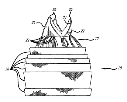
alternative
method on the other hand, is disclosed in U.S. Pat. No. 6,168,614
issued to Anderson et al. In this patent, the prosthetic valve is
mounted on a stent that is collapsed to a size that
fits within a catheter. The catheter is then inserted into the patient's
vasculature and
moved so as to position the collapsed stent at the location of the native
valve. A
deployment mechanism is activated that expands the stent containing the
replacement valve against the valve cusps. The expanded structure includes a
stent
configured to have a valve shape with valve leaflet supports begins to take on
the
function of the native valve. As a result, a full valve replacement has been
achieved
but at a significantly reduced physical impact to the patient.
[00061 However, this approach has decided shortcomings. One particular
drawback with the percutaneous approach disclosed in the Andersen '614 patent
is
the difficulty in preventing leakage around the perimeter of the new valve
after
implantation. Since the tissue of the native valve remains within the lumen,
there is a
strong likelihood that the commissural junctions and fusion points of the
valve tissue
(as pushed apart and fixed by the stent) will make sealing around the
prosthetic
valve difficult. in practice, this has often led to severe leakage of blood
around the
stent apparatus.
- 2 -
CA 02613958 2008-01-07
WO 2006/128193
PCT/US2006/021021
[0007] Other drawbacks of the Andersen '614 approach pertain to its
reliance on
stents as support scaffolding for the prosthetic valve. First, stents can
create emboli
when they expand. Second, stents are typically not effective at trapping the
emboli
they dislodge, either during or after deployment. Third, stents do not
typically
conform to the features of the native lumen in which they are placed, making a
prosthetic valve housed within a stent subject to paravalvular leakage.
Fourth,
stents are subject to a tradeoff between strength and compressibility. Fifth,
stents
cannot be retrieved once deployed. Sixth, the inclusion of the valve within
the stent
necessarily increases the collapsed diameter of the stent-valve complex and
increases the caliber of the material that must be delivered into the
vasculature.
[0008] As to the first drawback, stents usually fall into one of two
categories: self-
expanding stents and expandable stents. Self-expanding stents are compressed
when loaded into a catheter and expand to their original, non-compressed size
when
released from the catheter. These are typically made of Nitinol. Balloon
expandable
stents are loaded into a catheter in a compressed but relaxed state. These are
typically made from stainless steel or other malleable metals. A balloon is
placed
within the stent. Upon deployment, the catheter is retracted and the balloon
inflated,
thereby expanding the stent to a desired size. Both of these stent types
exhibit
significant force upon expansion. The force is usually strong enough to crack
or pop
thrombosis, thereby causing pieces of atherosclerotic plaque to dislodge and
become emboli. If the stent is being implanted to treat a stenosed vessel, a
certain
degree of such expansion is desirable. However, if the stent is merely being
implanted to displace native valves, less force may be desirable to reduce the
chance of creating emboli.
[0009] As to the second drawback, if emboli are created, expanded stents
usually
have members that are too spaced apart to be effective to trap any dislodged
material. Often, secondary precautions must be taken including the use of nets
and
irrigation ports.
- 3 -
CA 02613958 2013-06-06
50871-20
(0010] The third drawback is due to the relative inflexibility of stents.
Stents
typically rely on the elastic nature of the native vessel to conform around
the stent
Stents used to open a restricted vessel do not require a seal between the
vessel and
the stent. However, when using a stent to displace native valves and house a
prosthetic va(ve, a seal between the stent and the vessel is necessary to
prevent
paravalvular leakage. Due to the non-conforming nature of stents, this seal is
hard
to achieve, especially when displacing stenosed valve leaflets.
[0011] The fourth drawback is the tradeoff between compressibility and
strength.
Stents are made stronger or larger by manufacturing them with thicker members.
Stronger stents are thus not as compressible as weaker stents. Most stents
suitable
for use in a valve are not compressible enough to be placed in a small
diameter
catheter, such as a 20Fr, 16Fr or even 14Fr catheter. Larger delivery
catheters are
more difficult to maneuver to a target area and also result in more trauma to
the
patient.
[0012] The fifth drawback of stents is that they are not easily
retrievable. Once
deployed, a stent may not be recompressed and drawn back into the catheter for
repositioning due to the non-elastic deformation (stainless steel) or the
radial force
required to maintain the stent in place (Nitinol). Thus, if a physician is
unsatisfied
with the deployed location or orientation of a stent, there is little he or
she can do to
correct the problem.
(00131 The sixth drawback listed above is that the combination of the
valve within
the stent greatly increases the size of the system required to deliver the
prosthetic
device. As a result, the size of the entry hole into the vasculature is large
and often
precludes therapy, particularly in children, smaller adults or patients with
pre-existing
vascular disease.
(0014] Thus some embodiments of the present invention may address these
drawbacks. Specifically, some embodiments of the invention may provide a
support structure that expands gently, with gradual force, thereby minimizing
the generation of emboli.
- 4 -
CA 02613958 2013-06-06
50871-20
[0015] Some embodiments of the invention may provide a support
structure
that traps any emboli generated, thereby preventing the emboli from causing
damage
downstream.
[0016] Some embodiments of the invention may provide a support
structure
that conforms to the features of the lumen in which it is being deployed,
thereby
preventing paravalvular leakage.
[0017] Some embodiments of the invention may provide a strong support
structure capable of being deployed from a very small diameter catheter.
[0018] Some embodiments of the invention may provide a support
structure
that is capable of being retracted back into a delivery catheter and
redeployed
therefrom.
[0019] Some embodiments of the invention may provide a device that is
delivered with the valve distinctly separated from the inside diameter of the
final
configuration of the support structure in order to reduce the amount of space
required
to deliver the device within the vasculature of the patient.
BRIEF SUMMARY OF THE INVENTION
[0020] An embodiment of the invention provide a tubular mesh support
structure for a native lumen that is capable of being delivered via a very
small
diameter delivery catheter. The tubular mesh is formed one or more fine
strands
braided together into an elongate tube. The strands may be fibrous, non-
fibrous,
multifilament, or monofilament. The strands exhibit shape memory such that the
elongate tube may be formed into a desired folded shape, then stretched out
into a
very small diameter, elongated configuration. The small diameter, elongated
configuration makes a very small diameter delivery catheter possible.
[0021] Upon deployment, the elongated tube is slowly pushed out of the
delivery catheter, where it gradually regains its folded, constructed
configuration. The
- 5 -
CA 02613958 2013-06-06
50871-20
tube conforms to the internal geometries of the target vessel. In addition,
the braid
effectively traps all emboli that may be released from the vessel walls.
[0022] As the tube continues to be pushed from the delivery catheter,
it begins
to fold in upon itself as it regains its constructed configuration. As it
folds in upon
itself, the forces exerted by each layer add together, making the structure
incrementally stronger. Thus, varying levels of strength may be achieved
without
changing the elongated diameter of the device.
[0023] Using this folded tube, the valve can be attached such that
the valve or
other structure (such as a filter) in its elongated configuration within the
delivery
catheter does not reside within the elongated tube, but on deployment can be
positioned in, above or below the tube.
[0023a] Another embodiment of the invention provides a stentless
support
structure comprising: at least one strand braided to form a tubular implant
structure
having an unfolded delivery configuration and a folded delivered
configuration;
whereby in the unfolded delivery configuration, the tubular structure
includes: a first
end and a second end; an elongate tubular body between the first end and the
second end; whereby in the folded delivered configuration, the tubular
structure
includes at least one fold in the elongate tubular body creating a section of
the body
having at least twice as many layers as the elongate tubular body in the
unfolded
delivery configuration.
[0023b] A further embodiment of the invention provides a stentless
support
structure comprising: a strand braided to form a tubular implant having a
first
configuration and a second configuration; whereby in the first configuration,
the
tubular structure includes: a first end and a second end; an elongate tubular
body
between the first end and the second end; whereby in the second configuration,
the
tubular structure includes: at least one fold shortening the body and creating
a
section of the body having at least twice as many layers as the elongate body
in the
first configuration.
- 6 -
CA 02613958 2013-06-06
=
50871-20
BRIEF DESCRIPTION OF THE DRAWINGS
[0024] Figure 1 is a perspective view of a preferred embodiment of
the present
invention in an elongate configuration;
[0025] Figure 2 is a side view of a preferred embodiment of the
present
invention;
[0026] Figures 3-12 are a sequence of perspective views of a
preferred
embodiment of the present invention being deployed from a delivery catheter;
[0027] Figure 13 is a perspective view of a preferred embodiment of
the
present invention;
[0028] Figure 14 is a first end view of the preferred embodiment of Figure
13;
[0029] Figure 15 is a second end view of the preferred embodiment of
Figure 13;
[0030] Figure 16 is a side view of a preferred embodiment of the
present
invention;
[0031] Figure 17 is a second end view of the preferred embodiment of
Figure 16;
- 6a -
CA 02613958 2008-01-07
WO 2006/128193
PCT/US2006/021021
[0032] Figure 18 is a first end view of the preferred embodiment of Figure
16;
[0033] Figure 19 is a side view of a preferred embodiment of the present
invention;
[0034] Figure 20 is a first end view of the preferred embodiment of Figure
19;
[0035] Figure 21 is a second end view of the preferred embodiment of Figure
19;
[0036] Figure 22 is a partial perspective view of a preferred embodiment of
the
present invention;
[0037] Figure 23 is a partial perspective view of a preferred embodiment of
the
present invention;
[0038] Figure 24 is a perspective view of a preferred embodiment of the
present
invention;
[0039] Figure 25 is a side elevation of the embodiment of Figure 24;
[0040] Figure 26 is a second end view of the embodiment of Figure 24;
[0041] Figures 27-36 are a sequence of perspective views of a preferred
embodiment of the present invention being deployed from a delivery catheter
against
a clear plastic tube representing a native valve;
[0042] Figure 37 is a side elevation of a preferred embodiment of the
present
invention;
[0043] Figure 38 is an end view of a downstream side of the embodiment of
Figure 37;
[0044] Figure 39 is an end view of an upstream side of the embodiment of
Figure
37.
- 7 -
CA 02613958 2008-01-07
WO 2006/128193
PCT/US2006/021021
DETAILED DESCRIPTION OF THE INVENTION
[0045] Referring now to the Figures and first to Figure 1, there is shown a
stentless support structure 10 of the present invention in an extended
configuration.
The valve support 10 includes a first end 12, a second end 14 and an elongate
tubular body 16 extending between the first end 12 and the second end 14.
[0046] The elongate tubular body 16 is preferably formed from one or a
plurality
of braided strands 18. The braided strands 18 are strands of a super-elastic
or
shape memory material such as Nitinol. The strands are braided to form a tube
having a central lumen 20 passing therethrough.
[0047] In one embodiment, the tubular body 16 is folded in half upon itself
such
that the second end 14 becomes a folded end and the first end 12 includes a
plurality of unbraided strands. The tubular body 16 is thus two-ply. The
unbraided
strands of the first end 12 are gathered and joined together to form a
plurality of
gathered ends 22. The gathered ends 22 may be used as commissural points for
attaching a prosthetic valve to the support structure 10. (See, e.g. Figure
2).
Alternatively, as shown in Figure 1, the gathered ends 22 may be used as
attachment points for a wireform 24 defining a plurality of commissural points
26.
[0048] Notably, the commissural points 26 are positioned such that, when a
valve
is attached to the support structure in the extended configuration, the valve
is
longitudinally juxtaposed with the support structure rather than being located
within
the support structure. This juxtaposition allows the support structure 10 and
valve to
be packed into a very small catheter without damaging the delicate valve. This
longitudinal juxtaposition may be maintained when the support structure
assumes a
folded or constructed configuration (see Fig. 19 for example), or the valve
may
become folded within the support structure.
[0049] Figures 3-6 show the second end 14 emerging from the catheter 28 to
expose a first layer 30. In Figure 7, the first layer 30 is completely exposed
and has
assumed its constructed configuration. Notably,
the first layer 30 contracts
- 8 -
CA 02613958 2008-01-07
WO 2006/128193
PCT/US2006/021021
longitudinally when fully deployed. Also shown in Figure 7 is a second layer
32
beginning to emerge from the catheter 28. As the second layer exits the
catheter,
the pre-set super-elastic fold inverts the mesh, such that a second, inner
layer is
formed within the first outer layer. Alternatively, the first layer can be
deployed
against the wall of the vascular structure (such as an artery, vein, valve or
heart
muscle). As the second layer exits the catheter, the physician can aid
inversion of
the mesh my advancing the deployment system. In another embodiment, the mesh
support structure can be advanced in the vasculature such that it is deployed
in a
reverse direction (such as deployment through the apex of the heart ventricle
or from
the venous system), where the mesh inversion occurs as a result of pulling or
retracting the deployment system.
[0050] In Figure 10, the second layer 32 is fully deployed and the third
layer 34 is
fully exposed, but has not yet been inverted. Retracting the catheter 28,
relative to
the device 10, while advancing the catheter 28 slightly, relative to the
target site,
causes the third layer 34 to "pop" inwardly, thereby inverting itself against
an inside
surface of the second layer 32, as seen in Figure 11.
[0051] In Figure 12, additional material has been ejected from the catheter
28
such that the third layer 34 is fully expanded against the second layer. One
skilled in
the art will realize that numerous additional layers can be achieved in this
manner,
and that each layer adds additional radial strength to the resulting support
structure
10.
[0052] Throughout the deployment process, the stentless support structure
10
emerges from the delivery catheter 28 gradually. This characteristic also
allows the
structure 10 to be pulled back into the delivery catheter 28, in the event
that it is
desired to relocate the support structure 10. Doing so causes the support
structure
to reacquire its extended configuration.
[0053] Having described the mechanics of building a support structure in
situ,
attention can now be turned to various embodiments made possible by the
present
- 9 -
CA 02613958 2008-01-07
WO 2006/128193
PCT/US2006/021021
invention. Figures 13-15 show a support structure 10 having many layers 38 and
a
first end 12 with numerous gathered ends 22 formed from unbraided strands.
Some
of the gathered ends 22 are attached to a wireform 24 having three commissural
points 26. A prosthetic valve 36, either harvested or manufactured, is
attached to
the wireform 24. Figure 15 shows the internal lumen 20 of the support
structure 10.
[0054] Figures
16-18 show a support structure 10 having fewer layers 38 and a
wireform 24 with a prosthetic valve 36 attached thereto. The first end 12
(hidden), to
which the wireform 24 is attached, has been preformed to fold inwardly upon
deployment. Thus, the wireform 24 and prosthetic valve 36, is located in the
inner
lumen 20 of the support structure 10 when the support structure 10 is in a
constructed configuration.
possi Figures
19-21 show a support structure 10 with several layers 38 and a
first end 12 preformed to have a smaller diameter than the rest of the layers
and the
second end 14, which is folded. The terminal ends of the braided strands at
the first
end 12 have not been formed into gathered ends. Rather, the wireform 24 is
attached to the braids. The prosthetic valve 36 is attached to the wireform 24
and
has skirting tissue 40, which is placed around the outside of the end 12. The
skirting
tissue 40 may be adhered to the first end 12.
[0056] Figure
22 shows a stentless support structure 10 with a folded end 14,
which has been folded back on itself, and a material 42 trapped between the
two
layers of the fold. The material 42 is provided to further improve the
paravalvular
leak prevention and embolic trapping characteristics of the stentless support
structure 10. The material 42 could consist of a non-woven material, woven or
braided fabric, a polymer or other material.
[0057] Figure
23 shows a stentless support structure 10 that includes a fiber 44
that is larger than the rest of the strands comprising the support structure
10. Thus,
Figure 23 demonstrates that strands of different sizes may be used in the
braided
support structure 10 without significantly affecting the minimum delivery size
of the
- 10 -
CA 02613958 2008-01-07
WO 2006/128193
PCT/US2006/021021
device. Different sized strands may be used in order to improve strength,
provide
stiffness, create valve attachment points, provide radiopaque markers, and the
like.
[0058] Figures 24-26 show a stentless support structure 10 that has a first
end 12
that has had the unbraided strands trimmed such that they do not extend past
the
first end 12 of the folded structure 10. This embodiment may be used to
create,
preserve or enlarge a lumen. A prosthetic valve may or may not be attached to
this
embodiment.
[0059] Turning now to Figures 27-36, a deployment sequence of a preferred
embodiment of the stentless support structure 10 is shown whereby a clear
piece of
tubing 46 is used to demonstrate a targeted location of a native vessel, such
as a
native valve. In Figure 27, the delivery catheter 28 is advanced beyond the
targeted
valve 46 and the stentless support 10 is starting to be ejected from the
catheter 28.
[0060] In Figure 28, enough of the stentless support 10 has been ejected
that the
second, folded end 14 has begun to curl back on itself slightly, forming a
cuff 48. In
Figure 29, the cuff 48 is more visible and has assumed its full, deployed
shape. The
cuff 48 acts as a catch that a physician can use to visually or tactilely
locate the
targeted valve 46 and seat the stentless support 10 thereagainst. The cuff
also acts
to ensure the entire native lumen through the targeted valve 46 is now being
filtered
by the support 10. Unlike balloon expandable stents, blood flow is not
significantly
inhibited by the deployment of the stentless support structure 10. Also shown
in
Figure 29 is that the first layer 30 has been fully ejected from the catheter
28, as has
much of the second layer 32. The first layer 30, being very flexible prior to
reinforcement by subsequent layers, is able to conform to any shape of the
targeted
vessel. The second layer 32 has not yet inverted itself into the first layer
30.
[0061] In Figure 30, the first layer 30 is deployed, the cuff 48 is acting
against the
valve 46, and the second layer 32 has been inverted. In Figure 31, material
forming
the third layer 34 is ejected from the catheter 28 but the third layer 34 has
not yet
inverted.
- 11 -
CA 02613958 2008-01-07
WO 2006/128193
PCT/US2006/021021
[0062] In Figures 32-33, the catheter 28 is being advanced to allow tne
tnira layer
34 to invert into the second layer 32. The angle of Figure 32 shows the
relatively low
profile created by the first and second layers 30 and 32, and how little
resistance to
blood flow is presented by the support structure 10.
[0063] In Figure 34, the first end 12 has emerged from the catheter 12, and
the
gathered ends 22 are showing. A wireform 24 is attached to some of the
gathered
ends 22 and is nearly completely deployed from the delivery catheter 28. In
Figures
35-36, the support structure 10 has been completely released from the catheter
28.
Figure 36 shows the size of the lumen 20 of the support structure 10.
[0064] Figures 37-39 show a preferred embodiment 100 of the present
invention
including a mesh support structure 102, a wireform 104 and a valve 106. The
support structure 102 differs slightly from support structure 10, described
previously,
as it is constructed from a two individual wires 108. Upon completion of the
braiding
process, the two free ends of the wire are spliced together. As such, there
are no
free wire ends and the structure can be loaded into a delivery catheter in a
single-ply
state (not shown). In the deployed state shown in the Figures, the support
structure
102 is folded once to form a two-ply device.
[0065] The support structure 102 is preferably formed of a memory alloy
such as
Nitinol. The single-wire construction allows the device to be compressed into
an
extremely small catheter, such as one sized 16Fr or smaller. Though the
support
structure gains rigidity by the two-ply deployed configuration, radial
strength is a
function of a several factors and can thus be varied widely.
[0066] First, as with the other embodiments, radial strength may be
increased by
incorporating more folds or layers into the deployed configuration of the
support
structure 102. The three-ply configuration shown in Figures 37-39 is the most
preferred configuration because it only has to be folded in on itself twice,
making
deployment less complicated.
- 12 -
CA 02613958 2008-01-07
WO 2006/128193
PCT/US2006/021021
[0067] Second, strength may be increased by using a heavier wire. Because
the
support structure 102 is made from a single-wire, and can thus be loaded into
a
catheter in a single-ply configuration, a larger diameter wire may be used
while
maintaining a small diameter elongated profile. Support structures '102 have
been
constructed according to the present invention using single wires having
diameters
between 0.005 and 0,010 inches in diameter. Preferably, the diameter of the
wire is
between 0.007 and 0.008 inches.
[0068] Third, strength may be increased by increasing the braid density. A
tighter
braid will result in a stronger support.
[0069] Fourth, the strength may be increased by altering the heat setting
parameters. Super-elastic and shape memory alloys, such as Nitinol, attain
their
deployed shape within the vasculature by being heat set. The wires are held in
a
desired configuration and heated to a predetermined temperature for a
predetermined period of time. After the wires cool, they= become set to the
new
configuration. If the wires are later disfigured, they will return to the set
configuration
upon heating or simply releasing the wires. The force with which a super-
elastic or
shape memory alloy returns to a set configuration can be increased by
modifying the
temperature at which the configuration is set, or by modifying the period of
time the
alloy is maintained at the elevated setting temperature. For example, good
results
have been attained setting a Nitinol support structure of the present
invention at
530 C for 7 minutes. Stiffer support structures can be made using the same
Nitinol
wire by setting the structure at a temperature other than 530 C or by setting
the
structure at 530 C for a time other than 7 minutes, or both.
[0070] The device 100 includes a wireform 104, to which a valve 106 is
attached.
The wireform 104 form commissural points 109 separated by arcuate portions
110.
The arcuate portions 110 are attached to an inside surface of the support
structure
102. The commissural points 109 facilitate natural and efficient opening and
closing
of the valve 106. Alternatively, the valve commissural points can be attached
to an
outer surface of the support structure (not shown).
- 13 -
CA 02613958 2008-01-07
WO 2006/128193
PCT/US2006/021021
[0071] The valve 106 may be any form of prosthetic or harvested biological
valve.
Preferably, as shown in the Figures, the valve 106 is a valve having three
leaflets.
The valve 106 is sutured or otherwise attached to the wireform 104.
Preferably, the
valve 106 is cut or constructed to include a skirt portion 112 which continues
along
the length of the support structure 102 in its deployed configuration.
[0072] Although the invention has been described in terms of particular
embodiments and applications, one of ordinary skill in the art, in light of
this teaching,
can generate additional embodiments and modifications without departing from
the
spirit of or exceeding the scope of the claimed invention. Accordingly, it is
to be
understood that the drawings and descriptions herein are proffered by way of
example to facilitate comprehension of the invention and should not be
construed to
limit the scope thereof.
- 14-