Note: Descriptions are shown in the official language in which they were submitted.
CA 02614243 2008-01-04
WO 2007/006017 PCT/US2006/026389
FIVE-ELEMENT OPTICAL DEVICE
Field of the Invention
This invention generally relates to optical systems
comprising one or more optical devices and more particularly
to a lens form adapted for use in a variety of optical
devices.
Description of Related Art
Optical systems include one or more of a variety of
optical devices. A particular application will determine
the selection of specific optical devices to be included in
the optical system. As an example, in the medical field
optical systems serve as endoscopes. A rigid endo,scope.
includes multiple optical devices, namely: an objective, a
relay and an eyepiece. In the photographic field a camera
as an optical system includes an objective as an optical
device. Monoculars and telescopes incorporate eyepieces to
present an image for viewing. Night vision systems include
an optical device in the form of an eyepiece for allowing a
user to view an image projected from the phosphor output
screen of an image intensifier tube.
Significant efforts have been made to develop lens
forms for each of the foregoing and other optical devices.
Some of these efforts have led to highly specialized lens
forms that are adapted for a single use, such as an
objective for a camera, but not for use with another type of
optical device, such as a relay. In these applications the
number and attendant costs of optical elements, such as
lenses or mirrors, are secondary to requisite image quality.
For other applications, a lens designer seeks to produce a
lens based upon a lens form that essentially satisfies
CA 02614243 2008-01-04
WO 2007/006017 PCT/US2006/026389
- 2 -
optical requirements for the application with the fewest
possible optical elements. In such applications the lens
designer may also address issues such as physical size,
weight and manufacturing costs.
For example, U.S. Patent No. 716,035 (1902) to Harting,
U.S. Patent No. 1,421,156 (1922) to Booth, U.S. Patent No.
2,645,156 (1953) to Tronnier and U. S. Patent No. 2,645,157
(1953) to Lowenthal.disclose photographic objectives having
as a lens form three air-spaced lens elements. Each has an
intermediate optical element comprising a "negative" singlet
lens; the outer two optical elements comprise doublet lenses
that have the characteristics of a "positive" lens.
As used herein, the terms "positive" and "negative"
follow industry practice.s for optical devices using lenses
with centered, flat or spherical surfaces. A"posi.tive"
lens has a positive effective focal length arid typically has
a thicker central thickness along a central axis than edge
thickness. A"negative" lens has a negative effective focal
length and typically has a thinner central-thickness along a
central,axis than an edge thickness.
In each of the foregoing photographic objectives the
lens form uses lenses to control the Petzval Sum for the
optical device. The Petzval Sum is a measure of the
curvature of an image from any lens element or group of lens
elements in an optical device. This value is obtained by
summing, for each lens element in the optical device, the
product of the lens element power and refractive index of
the glass for that lens element. As the Petzval Sum
decreases, the curvature of the image also decreases.
However, the lenses in the foregoing references are
CA 02614243 2008-01-04
WO 2007/006017 PCT/US2006/026389
- 3 -
characterized by o.ther aberrations to blur fine lines
thereby to provide a "soft" image.
U.S. Patent No. 2,586,866 (1952) to Schade discloses a
high aperture five-component objective including a central
bi-convex negative lens and four positive lenses. The
positive lenses are concave-convex or bi-convex lenses, and
the second interlens space from the front of the objective
has the largest dimension. This configuration has the
object of projecting a focused image onto a curved surface
that is concave toward the objective.
U.S. Patent No. 2,900,871 (1959) to Baker disclose a
magnifier with three air-spaced optical elements including
an intermediate negative lens two outer doublet lenses that
have the characteristics of positive lenses. The magnifiers
are designed to enable the stereoscopic viewing of a map.
U.S. Patent No. 3,586,418 (1971) to Abe discloses an
eyepiece with four air-spaced optical devices between an
object and pupil. The optical element closest to the object
is a negative singlet lens. The remaining three optical
elements include a singlet lens and two doublet lenses.
Each of these three optical elements has the characteristics
of positive lenses.
The foregoing references disclose lens forms with
minimal number of lens elements in an objective. However,
the purpose of providing an image with these lens forms runs
counter to a purpose, in many applications, of lens forms in
eyepieces and other optical devices for providing a clear
image.
For some eyepieces, it is important to consider eye relief
in developing a lens form. As known, eye relief is the
distance of the eye from the eye lens of an optical device
CA 02614243 2008-01-04
WO 2007/006017 PCT/US2006/026389
- 4 -
that is best suited to the use of the optical system
incorporating the eyepiece. U. S. Patent No. 3,612,662
(1970) to Sissel discloses an eyepiece having a wide field
of view and a predetermined eye relief of about 28 mm with
an effective focal length of about 27.4 mm, a field of view
of 48.98 degrees, a back focal length of 10.6 mm and an exit
pupil of 10 mm. The eyepiece comprises, rearward from its
front end facing the object, a double convex singlet, a
negative meniscus-shaped double concave to the front, a
positive meniscus-shaped doublet concave to the front, a
double concave singlet, two double convex singlets and a
positive meniscus-shaped doublet convex to the front.
U. S. Patent No. 3,658,412 (1972) to Seaman discloses a wide
angle binocular eyepiece with four air-spaced optical
devices to provide a 75-80 mm eye relief, a field of view of
50 and an exit pupil of 80 mm. These devices include a
positive meniscus lens convex to the observer, a concave-
convex doublet consisting of a positive lens and a negative,
a positive meniscus lens conVex to the observer, and a
positive concave-convex lens convex to the observer. When
compared to the disclosure in U. S. Patent No. 3,612,662, it
cari be seen that U. S. Patent No. 3,658,412 reduces the
number of optical elements from ten to four thereby tending
to reduce the costs and weight of the resulting eyepiece.
Thus for each particular eyepiece application a lens
designer must select from a variety of lens forms that
satisfy requirements for eye relief, focal distances, field
of view, image curvature, magnifications, aberrations and
other factors. If a lens form is selected and then a
parameter, such as eye relief, changes, that change, at a
minimum, will require recalculation for some of the
CA 02614243 2008-01-04
WO 2007/006017 PCT/US2006/026389
- 5 -
different optical element in the eyepiece. At the worst,
such a change will require a complete lens redesign.
What is needed is a single lens form that can be used for
designing a variety of optical devices, such as objectives,
relays and eyepieces. Further, such a lens form should
minimize the total number of optical elements and reduce the
costs of manufacturing different optical elements.
Preferably, the lens form should reduce the number of
different types of optical elements in the optical device.
What'is also needed is a lens form that can be readily
adapted for different applications and that can accommodate
changes in parameters such as eye relief for eyepieces.
Summary
Therefore it is an object of this invention to provide
lens form that can be adapted for different optical device
applications.
Another object of this invention is to provide a lens
form_that is adapted for different optical device
applications and that limits the number of optical elements.
Yet another object of this invention is to provide a
lens form that is adapted for different optical device
applications and that limits the types of optical elements
in the optical device.
Still another object of this invention is to provide a
lens form that enables certain parameters of an optical
device to be varied without a need to change the design of
any optical element.
Still yet another object of this invention is to
provide an eyepiece in which both the number of lenses and
the number of lenses with different parameters are limited.
CA 02614243 2008-01-04
WO 2007/006017 PCT/US2006/026389
- 6 -
Yet still another object.of this invention is to
provide an eyepiece according to a lens form that is readily
adapted to accommodate different values of eye relief.
In accordance with one aspect of this invention an
optical system includes a housing extending along an axis
with opposite open ends. The housing carries five air-
spaced lens elements. A first lens element is intermediate
the ends of the housing. Second and third lens elements are
positioned seriatim on the axis between the first lens
element and one end of the housing. Fourth and fifth lens
elements are positioned seriatim on the axis between the
first lens element and the other end of the housing. The
first lens element has the characteristic of one of positive
and negative lenses, and the second through fifth lens
elements have the characteristics of the other of the
positive and negative lenses and each of said second through
fourth lens elements has a plano-convex shape.
In accordance with another aspect of this invention, an
eyepiece for producing an image of an object in front of the
eyepiece includes a housing extending along an axis with
opposite open front and rear ends. The housing carries a
negative lens and four identical positive lenses. The
negative lens is intermediate the ends of the housing.
First and second pos.itive lenses are positioned seriatim
between the negative lens and the front end of the housing.
Third and fourth positive lenses are positioned seriatim
between the negative lens and the rear end of the housing.
In accordance with another aspect of this invention an
eyepiece is adapted for use with a night vision device with
a phosphor output screen. The eyepiece can be focused
relative to the output screen and comprises a housing, a
CA 02614243 2008-01-04
WO 2007/006017 PCT/US2006/026389
- 7 -
negative lens and four identical positive lenses. The
negative lens has an index of refraction of 1.923 and an
Abbe number of 18.9 and is in the housing intermediate the
front and rear ends. This negative lens has a front concave
surface with a radius of 41.7068 mm, a rear concave surface
with a radius of 78.466 mm and an axial thickness of 1.785
mm. Each positive lens has an index of refraction of 1.788,
an Abbe number of 47.4,'a front planar surface, a rear
convex surface with a radius of 38.835 mm and an axial
thickness of 4.050 mm. Each lens is mounted to the housing
such that the distance between the first and second positive
lenses is 0.524 mm, between the second positive and negative
lenses is 7.175 mm, between the negative and third positive
lenses is 1.351 mm and between the third and fourth p'ositive
lenses is 3.434 mm whereby the eyepiece has a distance from
the front positive lens to the screen of 12.88 mm and an eye
relief of 29 mm.
In accordance with yet another aspect of this
invention, an eyepiece is adapted for use with a night
vision device with a phosphor output screen. The eyepiece
can be focused relative to the output screen and comprises a
housing, a negative lens and four identical positive lenses.
The negative lens has an index of refraction of 1.923 and an
Abbe number of 18.9 and is in the housing intermediate the
front and rear ends. This negative lens has a front'concave
surface with a radius of 41.7068 mm, a rear concave surface
with a radius of 78.466 mm and an axial thickness of 1.785
mm. Each positiverlens has an index of refraction of
refraction of 1.788 and an Abbe number of 47.4, a front
planar surface, a rear convex surface with a radius of
38.835 mm and an axial thickness of 4.050 mm. Each lens is
CA 02614243 2008-01-04
WO 2007/006017 PCT/US2006/026389
_ 8 _
mounted to the housing such that the distance between the
first and second positive lenses is 3.511 mm, between the
second positive and negative lenses is 4.54 mm, between the
negative and third positive lenses is 2.151 mm and between
the third and fourth positive lenses is 2.856 mm whereby the
eyepiece has a distance from the front positive lens to the
screen of 10.58 mm and an eye relief of 29 mm.
Brief Description of the Drawings
The appended claims particularly point out and
distinctly claim the subject matter of this invention. The
various objects, advantages and novel features of this
invention will be more fully apparent from a reading of the
following detailed description in conjunction with the
accompanying drawings in which like reference numerals refer
to like parts, and in which:
FIG. 1 is a perspective view of an application for this
invention;
FIG. 2 is a cross section of an eyepiece as one
embodiment of a lens form of this invention; and
FIG. 3 is a ray trace for the eyepiece shown in FIG. 2.
Best Mode for Carrying Out the Invention
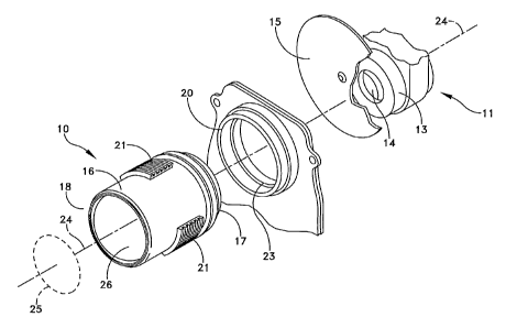
FIG. 1 depicts an optical device with a lens form in
the form of an eyepiece 10 associated with an optical system
in the form of a night vision system 11 all being mounted in
or on a base, not shown. The night vision system 11 includes
an image intensifier tube 13 with a phosphor output screen
14 for producing an object. FIG. 1 also depicts an optional
filter 15 for the image on the screen 14.
The eyepiece 10 includes a housing 16 with front and
rear openings 17 and 18, respectively. In this disclosure
CA 02614243 2008-01-04
WO 2007/006017 PCT/US2006/026389
- 9 -
the "front end" is the end of the eyepiece 10 that faces the
object.
In this particular embodiment the eyepiece 10 includes
a focus mechanism 20 including externally threaded segments
21 angularly spaced about the periphery of the housing 16
that engage an internal continuous thread 23 thereby to
enable a user to advance or retract the housing 16 along an
optical axis 24 for focus adjustment in a manner well known
in the art.
The distance between an exit pupil 25 and the rear
surface of an eye lens 26, which is one of several positive
lenses in the eyepiece 10, defines the eye relief. Thus an
individual using the apparatus shown in FIG. 1 positions her
or her eye at an approximate distance from the eye lens 26
corresponding to the eye relief. The viewed image can then
be focused to accommodate the user's eye.
FIG. 2 depicts the lens form of this invention as an
.eyepiece 10 with five air-spaced optical elements in the
form of lenses positioned in the housing 16. FIG. 2 also
depicts the position of the eyepiece 10 relative to an
object, such as the image intensifier tube screen 14 and the
exit pupil 25. In this implementation of the lens form, the
five air-spaced optical elements are constituted by five
air-spaced singlet lenses including the positive eye lens 26
and, from the front to rear, positive lenses 30 and 31, a
negative lens 32 and a positive lens 33. This
implementation of the five-element lens form can provide a
light-weight, compact eyepiece 10.
As shown in FIG. 2 the lenses 30, 31, 32 and 26 are
plano-convex singlet lenses that have the characteristics of
a positive lens while the singlet lens 32 is a bi-convex
CA 02614243 2008-01-04
WO 2007/006017 PCT/US2006/026389
- 10 -
lens having the characteristics of a negative lens. This
combination of positive and negative lenses provides a lens
designer a degree of control over the Petzval Sum for the
eyepiece 10. That is, the positive values of the lenses in
the Petzval Sum contributed by the four positive lenses 26,
30, 31 and 33 and the negative value for the negative lens
32 provide an offset to each other to minimize the Petzval
Sum. Such control is useful in matching the curvature of
the screen 14 thereby to minimize the field curvature of the
image produced by the eyepiece 10 or any other optical
device incorporating this lens form.
An optical device incorporating this lens form may also
provide another advantage. The eyepiece 10 includes four
positive lenses 26, 30, 31 and 33 with identical design
characteristics. Consequently, the lens form enables an
optical device to be constructed with five optical elements
taken from two different lens types. That is, the eyepiece
only requires the design of one negative lens and one
positive lens. This feature can improve manufacturing
efficiency over those associated optical devices having five
lenses or five different designs. The costs for acquiring
four identical positive lenses can be less than for four
different positive lenses. Moreover, during assembly it is
only necessary to discriminate between a positive lens and a
negative lens; there is no need to distinguish among a
plurality of different positive lenses that.differ only by
dimensions.
The foregoing and other advantages can be more fully
understood by considering the construction of two eyepieces,
such as the eyepiece 10, for two applications in which
object distance between.the screen 14 in FIG. 2 and the lens
CA 02614243 2008-01-04
WO 2007/006017 PCT/US2006/026389
- 11 -
30 changes. Each example has common design criteria,
namely:
Object size: 18 mm
Eye relief: 29 mm
Exit pupil: 14 mm
Apparent HFOV: 20
With these inputs and other input characteristics for
spherical and chromatic aberrations, coma,and astigmatism,
an eyepiece 10 has been constructed with the lens parameters
shown in Table I:
TABLE I
Lens Parameter Positive Lens Negative Lens
Front Radius co -78.466 mm
Rear Radius 38.835 mm 41.7068 mm
Center Thickness 4.050 mm 1.785 mm
,Glass SLAH 64 SNPH 2
Index of Refraction 1.788 1.923
Abbe Number , 47.4 18.9
Table II demonstrates how the lens form accommodates
different distances from the object to the front lens
without modifying the characteristics of the lenses in the
eyepiece. Example 1 sets forth the lens spacing for a
distance from the front lens to the object of 10.58 mm;
Example 2, a distance of 12.88 mm.
TABLE II
Spacing Example 1 Example 2
Lens 30 -Lens 31 3.511 mm 0.524 mm
Lens 31 - Lens 32 4.54 mm 7.175 mm
Lens 32 - Lens 33 2.151 mm 1.351 mm
CA 02614243 2008-01-04
WO 2007/006017 PCT/US2006/026389
- 12 -
Lens 33 - Lens 36 2.856 mm 3.434 mm
Eye Relief 29.00 mm 29.00 mm
EFL 27.05 mm 26.80 mm
BFL 10.58 mm 12.88 mm
HFOV 19.85 19.99
Pupil 14.00 mm 14.00 mm
More specifically, assume Example 1 is based on an
original design requiring 10.58 mm space between the object
and the front positive lens 30. Further assume that the
design process later requires a greater distance. Example 2
shows that distance beirig increased to 12.88 mm. Both
examples use the same lenses. The accommodation of this
change is achieved merely by altering the spacing between
adjacent lenses. Moreover other optical parameters of the
eyepiece 10 do not change to any significant extent.
FIG. 3 depicts a group of ray traces for an on-axis
focus point 34 and an off-axis, or full-field, focus point
35. A chief ray trace 34A from the on-axis focus point 34
passes through the eyepiece 10 along the axis 24. An upper
ray 34B and a lower ray 34C extend from the on-axis focus
point 35 at an angle that represents the cone of light from
the screen 14 at the on-axis focus point 34 that would pass
through a 14 mm diameter exit pupil at location 25.
Still referring to FIG. 3, the full-field focus point
35 is positioned at the periphery of the aperture for the
screen 14 and is shown with a chief ray 35A, upper ray 35B
and lower ray 35C. The angle between the upper and lower
rays 35B and 35C represents the cone of light from the,
screen 14 at the full-axis focus point that would fill a 14
mm diameter exit pupil at location 25. Each of the rays
CA 02614243 2008-01-04
WO 2007/006017 PCT/US2006/026389
- 13 -
35A, 35B and 35C are parallel and pass through the exit
pupil 25 at an angle. As known, the angle of the rays 35A,
35B and 35C to the axis 24 at the exit pupil 25 translates
into the position of the.full-field focus point 35 relative
to the axis 24.
As also shown in FIG. 3, the upper ray 35B passes
through the exit at a point offset from the optical axis 24.
The transverse distance at the exit pupil 25 from the center
axis 24 and the intersection of the ray 35B corresponds to
the user's pupil. As the user rotates his or her eye, the
eye receives rays of different angles that correspond to_
different' positions on the screen 14. Consequently the user
can scan the image over the entire field of view while
maintaining the image intensifier tube in a constant
position.
In low-light environments, including those that require
the use of night vision equipment, transmission through the
eyepiece 10 or other similar optical device may be enhanced
by applying an anti-reflective coating. As such coatings
are known in the art and very thin, they are not disclosed
in the figures.
Thus the lens form shown in FIG. 2 provides a unique
and powerful lens form for a range of optical devices. In
addition to the specifically disclosed eyepiece 10, the five
air-spaced element lens form has been used to design
objective and relay optical devices. An optical device can
be simply and easily constructed by limiting the five
optical elements to singlet lenses. Manufacturing
efficiencies can be realized by using four identical
positive lenses. Certain design variations can be
accommodated with this lens from merely by varying the
CA 02614243 2008-01-04
WO 2007/006017 PCT/US2006/026389
-'14 -
spacing parameters. Thus, it is possible to accommodate
changes in different user imposed requirements such as
distances from the.object to the eyepiece without having to
redesign the entire eyepiece.
This invention has been disclosed with respect to an
eyepiece that produces an image from the output of a curved
surface object constituted by a curved image intensifier
phosphor screen. It will be apparent that the design may be
further altered to accommodate a flat planar object. An
object may be an illuminated object or an illuminating
object such as a lamp source. The disclosure describes a
particular lens glass. Other glasses can be used. Any of
the five singlet lenses that constitute the five air-spaced
elements in this lens form can be replaced by a compound,.
lens that has the appropriate positive or negative lens
characteristics. Other variations will also be apparent to
those of ordinary skill in the art. Therefore, it is the
intent of the appended claims to cover all such variations
and modifications as come within the true spirit and scope
of this invention.