Note: Descriptions are shown in the official language in which they were submitted.
CA 02614246 2008-01-03
WO 2007/005810 PCT/US2006/025944
-1-
SAMPLE PROCESSING DEVICE COMPRESSION SYSTEMS AND METHODS
The present invention relates to systems and methods for using rotating sample
processing devices to, e.g., amplify genetic materials, etc.
Many different chemical, biochemical, and other reactions are sensitive to
temperature variations. Examples of thermal processes in the area of genetic
amplification include, but are not limited to, Polymerase Chain Reaction
(PCR), Sanger
sequencing, etc. One approach to reducing the time and cost of thermally
processing
multiple samples is to use a device including multiple chambers in which
different
portions of one sample or different samples can be processed simultaneously.
Examples of some reactions that may require accurate chamber-to-chamber
temperature control, comparable temperature transition rates, and/or rapid
transitions
between temperatures include, e.g., the manipulation of nucleic acid samples
to assist in
the deciphering of the genetic code. Nucleic acid manipulation techniques
include
amplification methods such as polymerase chain reaction (PCR); target
polynucleotide
amplification methods such as self-sustained sequence replication (3SR) and
strand-
displacement amplification (SDA); methods based on amplification of a signal
attached
to the target polynucleotide, such as "branched chain" DNA amplification;
methods
based on amplification of probe DNA, such as ligase chain reaction (LCR) and
QB
replicase amplification (QBR); transcription-based methods, such as ligation
activated
transcription (LAT) and nucleic acid sequence-based amplification (NASBA); and
various other amplification methods, such as repair chain reaction (RCR) and
cycling
probe reaction (CPR). Other examples of nucleic acid manipulation techniques
include, e.g., Sanger sequencing, ligand-binding assays, etc.
Some systems used to process rotating sample processing devices may be
described in U.S. Patent Application Publication No. US 2003/0124506 titled
MODULAR SYSTEMS AND METHODS FOR USING SAMPLE PROCESSING
DEVICES and U.S. Patent No. 6,734,401 titled ENHANCED SAMPLE
PROCESSING DEVICES SYSTEMS AND METHODS (Bedingham et al.)
SUMMARY OF THE INVENTION
The present invention provides sample processing systems and methods of
using those systems for processing sample materials located in sample
processing
CA 02614246 2008-01-03
WO 2007/005810 PCT/US2006/025944
-2-
devices that are separate from the system. The sample processing systems
include a
rotating base plate on which the sample processing devices are located during
operation
of the systems. The systems also include a cover and compression structure
designed
to force a sample processing device towards the base plate. The preferred
result is that
the sample processing device is forced into contact with a thermal structure
on the base
plate.
The systems and methods of the present invention may include one or more of
the following features to enhance thermal coupling between the thermal
structure and
the sample processing device: a shaped transfer surface, magnetic compression
structure, and floating or resiliently mounted thermal structure.
In embodiments that include a shaped thermal structure, the thermal structure
may preferably be provided with a transfer surface in the form of an annular
ring. It
may be preferred that the transfer surface have a convex curvature, e.g.,
similar to the
top section of a toroidal body. By providing a shaped transfer surface in
connection
with a cover and compression structure, thermal coupling efficiency between
the
thermal structure and the sample processing device may be improved. It may be
preferred that the cover include compression rings that force the sample
processing
device to conform to the shaped transfer surface of the thermal structure.
In embodiments that include magnetic compression structure, the cover and
base plate may preferably include magnetic elements that, through magnetic
attraction,
draw the cover towards the base plate. When a sample processing device is
located
between the cover and the base plate, the compression may improve thermal
coupling
between the sample processing device and the thermal structure. The magnets
may
preferably be permanent magnets. One potential advantage of a magnetic
compression
system is that the compressive forces may be obtained in an apparatus with
relatively
low mass - which may be useful in rotating systems.
In embodiments that include a floating or biased thermal structure, the
thermal
structure may preferably be resiliently biased towards the cover such that
force directed
downward on the thermal structure (from, e.g., the cover) may move the thermal
structure relative to the remainder of the base plate (which may preferably
remain
stationary). It may be preferred that the thermal structure be attached to the
base plate
using, e.g., one or more springs to provide the resilient bias and
structurally couple the
thermal structure to the base plate.
CA 02614246 2008-01-03
WO 2007/005810 PCT/US2006/025944
-3-
In one aspect, the present invention provides a system for processing sample
processing devices, the system including a base plate operatively coupled to a
drive
system, wherein the drive system rotates the base plate about a rotation axis,
wherein
the rotation axis defines a z-axis; thermal structure operatively attached to
the base
plate, wherein the thermal structure includes a transfer surface exposed
proximate a
first surface of the base plate; a cover facing the transfer surface, wherein
the cover
includes an inner compression ring and an outer compression ring; compression
structure operatively attached to the cover to force the cover in a first
direction along
the z-axis towards the transfer surface, wherein the inner and outer
compression rings
contact and urge a sample processing device located between the cover and the
transfer
surface into contact with transfer surface; and an energy source adapted to
deliver
thermal energy to the thermal structure while the base plate is rotating about
the
rotation axis.
In another aspect, the present invention provides a system for processing
sample
processing devices, the system including a base plate operatively coupled to a
drive
system, wherein the drive system rotates the base plate about a rotation axis,
wherein
the rotation axis defines a z-axis; thermal structure operatively attached to
the base
plate, wherein the thermal structure includes a transfer surface exposed
proximate a
first surface of the base plate; a cover facing the transfer surface; one or
more magnetic
elements operatively attached to the cover and base plate, wherein magnetic
attraction
between the one or more magnetic elements attached to the cover and the base
plate
draw the cover in a first direction along the z-axis towards the first surface
of the base
plate such that a sample processing device located between the cover and the
base plate
is urged into contact with the thermal structure of the base plate; and an
energy source
adapted to deliver thermal energy to the thermal structure while the base
plate is
rotating about the rotation axis.
In another aspect, the present invention provides a system for processing
sample
processing devices, the system including a base plate operatively coupled to a
drive
system, wherein the drive system rotates the base plate about a rotation axis;
a cover
facing a first surface of the base plate; compression structure operatively
attached to the
cover to force the cover towards the base plate; thermal structure operatively
attached
to the base plate; one or more resilient members operatively coupled to one or
both of
the cover and thermal structure, wherein the one or more resilient members
provide a
CA 02614246 2008-01-03
WO 2007/005810 PCT/US2006/025944
-4-
biasing force opposing the force of the compression structure forcing the
cover towards
the base plate, wherein a portion of a sample processing device located
between the
cover and the first surface of the base plate is urged into contact with the
thermal
structure; and an energy source adapted to deliver thermal energy to the
thermal
structure while the base plate is rotating about the rotation axis.
In another aspect, the present invention provides a method of processing
sample
material located within a sample processing device by locating a sample
processing
device between a base plate and a cover, wherein the sample processing device
includes
one or more process chambers located within an annular processing ring, and
wherein a
convex transfer surface is attached to the base plate, wherein the convex
transfer
surface is in the form of an annular ring that is in contact with the annular
processing
ring on the sample processing device; deforming the annular processing ring of
the
sample processing device on the convex transfer surface by forcing the cover
and the
base plate towards each other; and rotating the base plate, cover and sample
processing
device about an axis of rotation while deforming the annular processing ring
on the
convex transfer surface.
These and other features and advantages of the devices, systems and methods of
the invention are described below with respect to illustrative embodiments of
the
invention.
BRIEF DESCRIPTIONS OF THE FIGURES
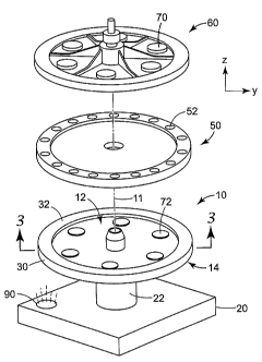
FIG. 1 is an exploded perspective view of one exemplary system according to
the present invention depicting a base plate and cover with a sample
processing device
located therebetween.
FIG. 2 is a plan view of an alternative arrangement of magnetic elements on a
base plate according to the present invention.
FIG. 3 is a perspective cross-sectional view of a portion of one base plate
with a
resiliently biased thermal structure according to the present invention.
FIG. 4 is a perspective view of one exemplary biasing member that may be used
in connection with the present invention.
FIG. 5 is an enlarged cross-sectional view of a cover forcing a sample
processing device to conform to a shaped transfer surface on a thermal
structure
according to the present invention.
CA 02614246 2008-01-03
WO 2007/005810 PCT/US2006/025944
FIG. 6 is a diagram depicting the radial cross-sectional profile of one
exemplary
shaped thermal transfer surface that may be used in connection with the
present
invention.
FIG. 7 is a diagram depicting the radial cross-sectional profile of another
exemplary shaped thermal transfer surface that may be used in connection with
the
present invention.
FIGS. 8A-8C depict alternative edge structures for compression rings on a
cover
according to the present invention.
FIG. 9 is a cross-sectional view of a portion of a sample processing device
that
may be used in connection with the present invention.
FIG. 10 is an enlarged plan view of a portion of the sample processing device
of
FIG. 9.
DESCRIPTION OF EXEMPLARY EMBODIMENTS OF THE INVENTION
In the following detailed description of exemplary embodiments of the
invention, reference is made to the accompanying figures of the drawing which
form a
part hereof, and in which are shown, by way of illustration, specific
embodiments in
which the invention may be practiced. It is to be understood that other
embodiments
may be utilized and structural changes may be made without departing from the
scope
of the present invention.
The present invention provides methods and systems for sample processing
devices that can be used in methods that involve thermal processing, e.g.,
sensitive
chemical processes such as PCR amplification, ligase chain reaction (LCR),
self-
sustaining sequence replication, enzyme kinetic studies, homogeneous ligand
binding
assays, and more complex biochemical or other processes that require precise
thermal
control and/or rapid thermal variations. The sample processing systems are
capable of
providing simultaneous rotation of the sample processing device in addition to
control
over the temperature of sample materials in process chambers on the devices.
Some examples of suitable sample processing devices that may be used in
connection with the methods and systems of the present invention may be
described in,
e.g., commonly-assigned U.S. Patent No. 6,734,401 titled ENHANCED SAMPLE
PROCESSING DEVICES SYSTEMS AND METHODS (Bedingham et al.) and U.S.
Patent Application Publication No. US 2002/0064885 titled SAMPLE PROCESSING
CA 02614246 2008-01-03
WO 2007/005810 PCT/US2006/025944
6
DEVICES. Other useable device constructions may be found in, e.g., U.S.
Provisional
Patent Application Serial No. 60/214,508 filed on June 28, 2000 and entitled
THERMAL PROCESSING DEVICES AND METHODS; U.S. Provisional Patent
Application Serial No. 60/214,642 filed on June 28, 2000 and entitled SAMPLE
PROCESSING DEVICES, SYSTEMS AND METHODS; U.S. Provisional Patent
Application Serial No. 60/237,072 filed on October 2, 2000 and entitled SAMPLE
PROCESSING DEVICES, SYSTEMS AND METHODS; U.S. Provisional Patent
Application Serial No. 60/260,063 filed on January 6, 2001 and titled SAMPLE
PROCESSING DEVICES, SYSTEMS AND METHODS; U.S. Provisional Patent
Application Serial No. 60/284,637 filed on April 18, 2001 and titled ENHANCED
SAMPLE PROCESSING DEVICES, SYSTEMS AND METHODS; and U.S. Patent
Application Publication No. US 2002/0048533 titled SAMPLE PROCESSING
DEVICES AND CARRIERS. Other potential device constructions may be found in,
e.g., U.S. Patent No. 6,627,159 titled CENTRIFUGAL FILLING OF SAMPLE
PROCESSING DEVICES (Bedingham et al.)
The sample processing systems of the present invention preferably include base
plates attached to a drive system in manner that provides for rotation of the
base plate
about an axis of rotation. When a sample processing device is secured to the
base plate,
the sample processing device is rotated with the base plate. The base plates
include at
least one thermal structure that can be used to heat portions of the sample
processing
devices and may include a variety of other components as well, e.g.,
temperature
sensors, resistance heaters, thermoelectric modules, light sources, light
detectors,
transmitters, receivers, etc.
Although relative positional terms such as "top", "bottom", "above", "below",
etc. may be used in connection with the present invention, it should be
understood that
those terms are used in their relative sense only. For example, when used in
connection
with the devices of the present invention, "top" and "bottom" may be used to
signify
opposing sides of the base plates, with the top surface typically located
closest to the
sample processing device mounted to the base plate during sample processing.
3p In actual use, elements described as "top" or "bottom" may be found in any
orientation or location and should not be considered as limiting the methods,
systems,
and devices to any particular orientation or location. For example, the top
surface of
the sample processing device may actually be located below the bottom surface
of the
CA 02614246 2008-01-03
WO 2007/005810 PCT/US2006/025944
sample processing device during processing (although the top surface would
still be
found on the opposite side of the sample processing device from the bottom
surface).
One illustrative sample processing system is schematically depicted in the
exploded perspective view of FIG. 1. The system includes a base plate 10 that
rotates
about an axis of rotation 11. The base plate 10 may preferably be attached to
a drive
system 20 through a shaft 22. It will, however, be understood that the base
plate 10
may be coupled to the drive system 20 through any suitable alternative
arrangement,
e.g., belts or a drive wheel operating directly on the base plate 10, etc.
Also depicted in FIG. 1 is a sample processing device 50 and cover 60 that may
preferably be used in connection with the base plate 10 as will be described
herein.
Systems of the present invention may not actually include a sample processing
device
as, in most instances, sample processing devices are consumable devices that
are used
to perform a variety of tests, etc. and then discarded. As a result, the
systems of the
present invention may be used with a variety of different sample processing
devices.
The depicted base plate 10 includes a thermal structure 30 that preferably
includes a transfer surface 32 exposed on the top surface 12 of the base plate
10. By
"exposed" it is meant that the transfer surface 32 of the thermal structure 30
can be
placed in physical contact with a portion of a sample processing device 50
such that the
thermal structure 30 and the sample processing device are thermally coupled to
transfer
thermal energy through conduction. It may be preferred that the transfer
surface 32 of
the thermal structure 30 be located directly beneath selected portions of a
sample
processing device 50 during sample processing. The selected portions of the
sample
processing device 50 may preferably include process chambers 52 as discussed
in, e.g.,
U.S. Patent No. 6,734,401 titled ENHANCED SAMPLE PROCESSING DEVICES
SYSTEMS AND METHODS (Bedingham et al.).
As discussed herein, the systems of the present invention may preferably
include a cover 60 that, together with the base plate 10, compress a sample
processing
device located therebetween to preferably enhance thermal coupling between the
thermal structure 30 on the base plate and the sample processing device 50. It
may be
preferred that both the sample processing device 50 and the cover 60 rotate
with the
base plate 10 as it is rotated about axis 11 by drive system 20.
The compressive forces developed between the base plate 10 and the cover 60
may be accomplished using a variety of different structures. One exemplary
CA 02614246 2008-01-03
WO 2007/005810 PCT/US2006/025944
-t5-
compression structure depicted in the embodiment of FIG. 1 are magnetic
elements 70
located on the cover 60 and corresponding magnetic elements 72 located on the
base
plate 10. Magnetic attraction between the magnetic elements 70 and 72 may be
used to
draw the cover 60 and the base plate 10 towards each other, thereby
compressing or
deforming a sample processing device 50 located therebetween.
As used herein, a"magnetic element" is a structure or article that exhibits
magnetic fields. The magnetic fields are preferably of sufficient strength to
develop the
desired compressive force that results in thermal coupling between a sample
processing
device 50 and the thermal structure 30 of base plate 10 as discussed herein.
The
magnetic elements may preferably include magnetic materials, i.e., materials
that either
exhibit a permanent magnetic field or that are capable of exhibiting a
temporary
magnetic field.
Some examples of potentially suitable magnetic materials include, e.g.,
magnetic ferrite or "ferrite" which is a substance including mixed oxides of
iron and
one or more other metals, e.g., nanocrystalline cobalt ferrite. However, other
ferrite
materials may be used. Other magnetic materials which may be utilized in the
construction of the device 50 may include, but are not limited to, ceramic and
flexible
magnetic materials made from strontium ferrous oxide which may be combined
with a
polymeric substance (such as, e.g., plastic, rubber, etc.); NdFeB (this
magnetic material
may also include Dysprosium); neodymium boride; SmCo (samarium cobalt); and
combinations of aluminum, nickel, cobalt, copper, iron, titanium, etc.; as
well as other
materials. Magnetic materials may also include, e.g., stainless steel or other
magnetizable materials that may be rendered sufficiently magnetic by
subjecting the
magnetizable material to a sufficient electric and/or magnetic field.
It may be preferred that the magnetic elements 70 and 72 be discrete articles
operably attached to the cover 60 and base plate 10 as depicted in the
embodiment of
FIG. 1(in which the magnetic elements 70 and 72 are disc-shaped articles). In
one
alternative, however, the base plate 10, thermal structure 30, and/or cover 60
may
contain sufficient magnetic material (e.g., molded or otherwise provided in
the structure
of the component) that separate, discrete magnetic elements are not required.
FIG. 2 is a view of one alternative arrangement of magnetic elements 172 on an
alternative base plate 110 that may preferably rotate about axis 111. As
depicted in
FIG. 2, the magnetic elements 172 may be smaller than those in the system
depicted in
CA 02614246 2008-01-03
WO 2007/005810 PCT/US2006/025944
-9-
FIG. 1. A potential advantage of such an arrangement may be found in a more
uniform
distribution of the magnetic force about the circumference of the base plate
110
(especially where the cover includes a complementary arrangement of magnetic
elements).
In another alternative, the cover 60 and/or base plate 10 may include one or
more magnetic elements in the form of electromagnets that can be activated as
needed
to provide the compressive force in place of passive magnetic elements. In
such an
embodiment, electric power would need to be provided to the electromagnets
during
rotation of the sample processing device 50.
Although not explicitly depicted in FIG. 1 the base plate 10 may preferably be
constructed such that the thermal structure 30 is exposed on both the top and
the bottom
surfaces 12 and 14 of the base plate 10. By exposing the thermal structure 30
on the
top surface 12 of the base plate 10, a more direct thermal path can be
provided between
the transfer surface 32 of the thermal structure 30 and a sample processing
device 50
located between the cover 60 and the base plate.10.
The thermal structure 30 is also preferably exposed on the bottom surface 14
of
the base plate 10. Exposing the thermal structure 30 on the bottom surface 14
of the
base plate 10 may provide an advantage when the thermal structure 30 is to be
heated
by electromagnetic energy emitted by a source directing electromagnetic energy
onto
the bottom surface 14 of the base plate 10.
Although the system of FIG. 1 includes an electromagnetic energy source to
deliver thermal energy to the thermal structure, the temperature of the
thermal structure
may be controlled by any suitable energy source that can deliver thermal
energy to the
thermal structure. Examples of potentially suitable energy sources for use in
connection with the present invention other than electromagnetic energy
sources may
include, e.g., Peltier elements, electrical resistance heaters, etc.
As used in connection with the present invention, the term "electromagnetic
energy" (and variations thereof) means electromagnetic energy (regardless of
the
wavelength/frequency) capable of being delivered from a source to a desired
location or
material in the absence of physical contact. Nonlimiting examples of
electromagnetic
energy include laser energy, radio-frequency (RF), microwave radiation, light
energy
(including the ultraviolet through infrared spectrum), etc. It may be
preferred that
CA 02614246 2008-01-03
WO 2007/005810 PCT/US2006/025944
-10-
electromagnetic energy be limited to energy falling within the spectrum of
ultraviolet to
infrared radiation (including the visible spectrum).
One example of an electromagnetic energy source 90 is depicted in FIG. 1, with
the electromagnetic energy emitted by the source 90 directed onto the bottom
surface
14 of the base plate 10 and the portion of the thermal structure 30 exposed on
the
bottom surface 14 of the base plate 10. Examples of some suitable
electromagnetic
energy sources may include, but are not limited to, lasers, broadband
electromagnetic
energy sources (e.g., wliite light), etc.
Where the thennal structure 30 is to be heated by a remote energy source,
i.e.,
an energy source that does not deliver thermal energy to the thermal structure
by direct
contact, the thermal structure 30 may preferably be constructed to absorb
electromagnetic energy and convert the absorbed electromagnetic energy into
thermal
energy. The materials used in the thermal structure 30 preferably possess
sufficient
thermal conductivity and absorb electromagnetic energy generated by the
electromagnetic source 90 at sufficient rates. In addition, it may also be
desirable that
the material or materials used for the thermal structures 30 have sufficient
heat capacity
to provide a heat capacitance effect. Examples of some suitable materials
include, but
are not limited to: aluminum, copper, gold, etc. If the thermal structure 30
is
constructed of materials that do not, themselves, absorb electromagnetic
energy at a
sufficient rate, it may be preferred that the thermal structure 30 include a
material that
iinproves energy absorption. For example, the thermal structure 30 may be
coated with
an electromagnetic energy absorptive material such as carbon black,
polypyrrole, inks,
etc.
In addition to selection of suitable materials for the thermal structure 30,
it may
also be preferred to include grooves or other surface structure facing the
electromagnetic energy source 90 to increase the amount of surface area
exposed to the
electromagnetic energy emitted by the source 90. Increasing the surface area
of the
thermal structure 30 exposed to the electromagnetic energy from source 90 may
enhance the rate at which energy is absorbed by the thermal structure 30. The
increased surface area used in the thermal structures 30 may also increase the
efficiency
of electromagnetic energy absorption.
It may fu.rther be desirable that the thermal structure 30 be relatively
thermally
isolated from the remainder of the base plate 10 such that only limited
amounts (if any)
CA 02614246 2008-01-03
WO 2007/005810 PCT/US2006/025944
-11-
of the thermal energy in the thermal structure 30 is transferred to the
remainder of the
base plate 10. That thermal isolation may be achieved, for example, by
manufacturing
the support structure of the base plate 10 of materials that absorb only
limited amounts
of thermal energy, e.g. polymers, etc. Some suitable materials for the support
structure
of base plate 10 include, e.g., glass-filled plastics (e.g.,
polyetheresterketone), silicones,
ceramics, etc.
Although the base plate 10 includes a thermal structure 30 in the form of a
substantially continuous circular ring, the thermal structures used in base
plates of
systems according to the present invention may alternatively be provided as a
series of
discontinuous thermal elements, e.g., circles, squares, located beneath
process
chambers on the sample processing device 50. One potential advantage, however,
of a
continuous ring thermal structure 30 is that temperature of the thermal
structure 30 may
equilibrate during heating. If a group of process chambers in a sample
processing
device are arranged such that they are in direct contact with the transfer
surface 32 of
the thermal structure 30, there is a potential to improve chamber-to-chamber
temperature uniformity for all process chambers located above the continuous
thermal
structure 30.
Although the depicted base plate 10 includes only one thermal structure 30, it
will be understood that base plates in the systems of the present invention
could include
any number of thermal structures that are necessary to transfer thermal energy
to or
from the selected process chambers in a sample processing device located
thereon.
Further, it may be preferred that, where more than one thermal structure is
provided,
the different thermal structures be independent of each other such that no
significant
amount of thermal energy is transferred between the different independent
thermal
structures. One example of an alternative in which independent thermal
structures are
provided may be in the form of concentric annular rings.
FIG. 3 is a perspective cross-sectional view of a portion of the base plate 10
and
thermal structure 30 of the system depicted in FIG. 1 taken along line 3-3 in
FIG. 1.
The base plate 10 includes main body 16 to which the thermal structure 30 is
attached.
Although not seen in FIG. 3, the main body 16 may preferably be fixedly
attached to a
spindle used to rotate the base plate 10. By fixedly attached, it is meant
that the main
body 16 preferably does not move relative to the spindle when a sample
processing
CA 02614246 2008-01-03
WO 2007/005810 PCT/US2006/025944
-12-
device is compressed between the cover 60 and the base plate 10 during
operation of
the system.
As depicted in FIG. 3, the thermal structure 30 may preferably be generally U-
shaped below the transfer surface 32. Such shaping may preferably accomplish a
number of functions. For example, the U-shaped thermal structure 30 may
increase the
surface area onto which electromagnetic energy is incident, thus potentially
increasing
the amount and rate at which energy is transferred to the thermal structure
30. In
addition, the U-shaped thermal structure may present a lower thermal mass for
the
thermal structure 30.
As discussed herein, one optional feature of systems of the present invention
is
the floating or suspended attachment of the thermal structure 30 such that the
thermal
structure 30 and the cover 60 are resiliently biased towards each other. It
may be
preferred that the thermal structure 30 be coupled to the base plate 10 by one
or more
resilient members, with the one or more resilient members providing a biasing
force
opposing the force applied by the compression structure (e.g., magnets). In
such a
system, it may be preferred that the thermal structure 30 be capable of
movement
relative to the main body 16 of the base plate 10 in response to compressive
forces
between the base plate 10 and the cover 60. Movement of the thermal structure
30 may
preferably be limited to a z-axis direction that is preferably aligned with
(preferably
parallel to) the axis of rotation.
Resilient coupling of the thermal structure 30 may be advantageous by
providing improved compliance with the surface of the sample processing device
50.
The floating attachment of the thermal structure 30 may help to compensate
for, e.g.,
surfaces that are not flat, variations in thickness, etc. Resilient coupling
of the thermal
structure 30 may also improve uniformity in the compressive forces developed
between
the cover 60 and the thermal structure 30 when a sample processing device 50
is
compressed between the two components.
Many different mechanisms may be used to resiliently couple the thermal
structure 30. One exemplary mechanism is depicted in FIGS. 3 and 4 in the form
of a
flat spring 40 that is attached to the main body 16 and the thermal structure
30. The
depicted flat spring 40 includes an inner ring 42 and spring arms 44 that
extend to an
outer ring 46. The inner ring 42 is attached to the main body 16 and the outer
ring 46 is
attached to a flange 36 on the thermal structure 30. Attachment of the spring
40 may be
CA 02614246 2008-01-03
WO 2007/005810 PCT/US2006/025944
-13-
accomplished by any suitable technique or techniques, e.g., mechanical
fasteners,
adhesives, solder, brazing, welding, etc.
The forces generated by the flat spring 40 may be adjusted by changing the
length of the cuts 45 defining the spring arms 44, changing the radial width
of the
spring arms 44, changing the thickness of the spring arms 44 (in the z-axis
direction),
selection of materials for the spring 40, etc.
It may be preferred that the force urging the base plate 10 and cover 60
towards
each other result in physical contact between the main body 16 of the base
plate 10 and
the cover 60 within the circle bounded by the inner edge of the transfer
surface 32 of
the thermal structure 30. In other words, the magnetic attraction force in the
depicted
embodiment preferably draws the cover 60 against the main body 16 of the base
plate
10. As a result, the forces exerted on the portion of the sample processing
device 50
clamped between the cover 60 and the transfer surface 32 are exerted by the
flat spring
40 (or other resilient members if used). In other words, control over the
clamping force
may preferably be controlled by the resilient member/flat spring 40.
To achieve the result described in the preceding paragraph it may be preferred
that the clamping force generated between the cover 60 and the main body 16 of
the
base plate 10 be greater than the biasing force operating to force the
transfer surface 32
of the thermal structure 30 towards the cover 60. As a result, the cover 60 is
drawn into
contact with the main body 16 and the resilient member (e.g., flat spring 40
in the
depicted embodiment) controls the forces applied to the sample processing
device 50
between the cover 60 and the transfer surface.
In the depicted embodiment an insulating element 38 is located between the
outer ring 46 and the flange 36. The insulating element 38 may serve a number
of
functions. For example, the insulating element 38 may reduce the transfer of
thermal
energy between the outer ring 46 of the spring 40 and the flange 36 of the
thermal
structure 30. Another potential function of the insulating element 38 may be
to provide
a pre-load to the spring 40 such that the force with which the thermal
structure 30 is
biased towards the top surface 12 of the base plate 10 is at or above a
selected level. A
thicker insulating element 38 would typically be expected to increase the pre-
load while
a thinner insulating element 38 would typically be expected to reduce the pre-
load.
Examples of some potentially suitable materials for insulating element may
include
CA 02614246 2008-01-03
WO 2007/005810 PCT/US2006/025944
-14-
materials with lower thermal conductivity than metals, e.g., polymers,
ceramics,
elastomers, etc.
Although a flat spring 40 is one example of a resilient meinber that can be
used
to resiliently couple the thermal structure 30, many other resilient members
could be
used in place of or in addition to the depicted flat spring 40. Examples of
some other
potentially suitable resilient members may include, e.g., leaf springs,
elastomeric
elements, pneumatic structures (e.g., pistons, bladders, etc.), etc.
Although the flat spring 40 and the main body 16 of the base plate 10 are
depicted as separate components in the exemplary embodiment of FIGS. 1 and 3,
alternatives may be possible which the functions of the main body 16 and the
spring 40
are accomplished in a single, unitary component.
One example of other optional features of sample processing systems of the
present invention is depicted in connection with FIG. 5 which is an enlarged
cross-
sectional view of a sample processing device 250 held under compression
between a
thermal structure 230 and a cover 260.
In the embodiment seen in FIG. 5, the transfer surface 232 of the thermal
structure 230 may preferably be a shaped surface with a raised portion located
between
an inner edge 231 and an outer edge 233 (where inner edge 231 is closest to
the axis of
rotation about which the thermal structure rotates as discussed herein). The
raised
portion of the transfer surface 232 may preferably be closer to the cover 260
than the
portions of the thermal structure at the inner and outer edges 231 and 233
before the
sample processing device 250 is contacted by the cover 260. The transfer
surface 232
may preferably have a convex curvature when seen in a radial cross-section as
depicted
in FIG. 5. The convex transfer surface 232 may be defined by a circular curve
or any
other curved profile, e.g., elliptical, etc.
FIGS. 6 and 7 depict alternative shaped transfer surfaces that may be used in
connection with thermal structures that are provided as, e.g., annular rings.
One such
variation as depicted in FIG. 6 includes a thermal structure 330 (depicted in
cross-
section to illustrate its profile). The thermal structure 330 includes a
shaped transfer
surface 332 with an inner edge 331 and an outer edge 333. The inner edge 331
is
located proximate an axis of rotation about which the thermal structure 330 is
rotated as
discussed herein. Also depicted is a plane 301 (seen on edge in FIG. 6) that
is
transverse to the axis of rotation.
CA 02614246 2008-01-03
WO 2007/005810 PCT/US2006/025944
In the depicted embodiment, the plane 301 extends through the outer edge 333
of the shaped transfer surface 332. Unlike the transfer surface 232 of FIG. 5
in which
the inner and outer edges 231 and 233 are located on the same plane, the inner
edge 331
of the transfer surface 332 may preferably be located at an offset (o)
distance from the
5 reference plane 301 as depicted in FIG. 6. It may be preferred that the
inner edge 331
of the transfer surface 332 be located closer to the cover (not shown) than
the outer
edge 333.
As discussed herein, the shaped transfer surface 332 may preferably include a
raised portion between the inner edge 331 and the outer edge 333. The height
(h) of the
10 raised portion is depicted in FIG. 6 relative to the plane 301, with the
height (h)
preferably representing the maximum height of the raised portion of the
transfer surface
332.
Although the shaped transfer surfaces 232 and 332 depicted in FIGS. 5 and 6
include a raised portion with a maximum height located between the inner and
outer
15 edges of the transfer surfaces, the maximum height of the raised portion
may
alternatively be located at the inner edge of the transfer surface. One such
embodiment
is depicted in FIG. 7 in which a cross-sectional view of a portion of a
thermal structure
430 is depicted. The thermal structure 430 includes a shaped transfer surface
432 with
an inner edge 431 and an outer edge 433 as discussed above. The transfer
surface 432
preferably includes a raised portion with a height (h) above a reference plane
401 that
extends through the outer edge 433 of the transfer surface 432.
Unlike the transfer surfaces of FIGS. 5 and 6, however, the raised portion of
the
transfer surface 432 has its maximum height (h) located at the inner edge 431.
From
the maximum height (h), the transfer surface curves downward in a convex curve
towards the outer edge 433. In such an embodiment, the inner edge 431 is
located at an
offset (o) distance from the reference plane 401 that is equal to the height
(h).
The amount by which the transfer surfaces 232, 332, 432 deviate from a planar
surface may be exaggerated in FIGS. 5-7. The height (h) may in some sense be a
function of the radial distance from the inner edge to the outer edge of the
transfer
surface. For transfer surfaces with a radial width of, e.g., 4 centimeters or
less,
preferably 2 centimeters or less, and even 1 centimeter or less, it may be
preferred that
the height (h) be within a range with a lower value greater than zero,
preferably 0.02
millimeters (mm) or more, more preferably 0.05 millimeters or more. At the
upper end
CA 02614246 2008-01-03
WO 2007/005810 PCT/US2006/025944
-16-
of the range, it may be preferred that the height (h) be 1 milliineter or
less, preferably
0.5 mm or less, and even 0.25 millimeters or less.
Returning to FIG. 5, by providing a shaped transfer surface in connection with
a
cover 260 and compression structure of the present invention, thermal coupling
efficiency between the thermal structure 230 and the sample processing device
250 may
be improved. The shaped transfer surface 232 in combination with the force
applied by
the cover 260 may preferably deform the sample processing device 250 such that
it
conforms to the shape of the transfer surface 232. Such deformation of the
sample
processing device 250 may be useful in promoting contact even if the surface
of the
sample processing device 250 facing the transfer surface 232 or the transfer
surface 232
itself include irregularities that could otherwise interfere with uniform
contact in the
absence of deformation.
If the sample processing device 250 includes process chambers (see, e.g.,
chambers 52 on sample processing device 50 in FIG. 1), it may be preferred to
provide
an optical window 268 in the cover 260 that allows transmission of
electromagnetic
energy through the cover 260. Such electromagnetic energy may be used to,
e.g.,
monitor process chambers, interrogate process chambers, heat process chambers,
excite
materials in the process chambers, etc. By optical window, it is meant that
the selected
portion of the cover 260 transmits electromagnetic with selected wavelengths.
That
transmission may be through transmissive materials or through a void formed in
the
cover 260.
To further promote deformation of the sample processing device 250 to
conform to the shape of the transfer surface 232, it may be preferred to
include
compression rings 262 and 264 in the cover 260, such that the rings 262 and
264
contact the sample processing device 250 - essentially spanning the portion of
the
sample processing device 250 facing the transfer surface 232. It may be
further
preferred that substantially all compression force transfer between the cover
260 and
the thermal structure 230 occurs through the inner and outer compression rings
262 and
264 of the cover 260.
To potentially further enhance conformance of the sample processing device
250 to the transfer surface 232, it may be preferred that the inner and outer
compression
rings 262 and 264 include an edge treatment 266 such that minor variations in
dimensions of the different components (cover, sample processing device,
thermal
CA 02614246 2008-01-03
WO 2007/005810 PCT/US2006/025944
-1"/-
structure, etc.) can be at least partially compensated for by the edge
treatments 266.
One example of suitable edge treatments may be a rounded structure that
promotes
point contact between the sample processing device-250 and the compression
rings 262
and 264. Other potential examples of potentially suitable edge treatments may
include,
e.g., a resilient gasket 366a depicted in FIG. 8A, a cantilevered member 366b
depicted
in FIG. 8B, and a triangular structure 366c as depicted in FIG. 8C.
In another variation, it should be understood that although the depicted
systems
include resilient members coupling the thermal structures to the base plates,
an
alternative arrangement could be used in which the inner and outer compression
rings
262 and 264 are resiliently coupled to the cover 260 by one or more resilient
members.
Resiliently mounting the compression rings 262 and 264 on the cover 260 may
also
serve to provide some compensation in the system for, e.g., surfaces that are
not flat,
variations in thickness, etc. Resilient coupling of the compression rings may
also
improve uniformity in the compressive forces developed between the cover 260
and the
thermal structure 230 when a sample processing device 250 is compressed
between the
two components.
As discussed herein, it may be preferred that the portion of the sample
processing device 250 in contact with the transfer surface 232 (or other
shaped transfer
surfaces) exhibit some compliance that, under compression, enables the sample
processing device 250 to conform to the shape of the transfer surface 232.
That
compliance may be limited to the portions of the sample processing device
located in
contact with the transfer surface 232. Some potentially suitable sample
processing
devices that may include a compliant portion adapted to conform to a shaped
thermal
transfer surface are described in, e.g., U.S. Patent Application No.
11/174,680, titled
COMPLIANT MICROFLUIDIC SAMPLE PROCESSING DISKS, filed on July 5,
2005 and U.S. Patent Application No. 11/174,756, titled MODULAR SAMPLE
PROCESSING APPARATUS AND METHODS, filed on July 5, 2005.
As discussed in the documents identified in the preceding paragraph,
compliance of sample processing devices may be enhanced if the devices include
annular processing rings that are formed as composite structures including
cores and
covers attached thereto using pressure sensitive adhesives. A portion of one
such
composite structure is depicted in FIG. 9 which includes a device 450 having a
body
480 to which covers 482 and 486 are attached using adhesives (preferably
pressure
CA 02614246 2008-01-03
WO 2007/005810 PCT/US2006/025944
-18-
sensitive adhesives) 484 and 488 (respectively). Where process chambers are
provided
in a circular array (as depicted in FIGS. 1 and 3) that is formed by a
composite structure
such as that seen in FIG. 9, the process chambers and covers may preferably
define a
compliant annular processing ring that is adapted to conform to the shape of
an
underlying thermal transfer surface when the sample processing disk is forced
against a
shaped thermal transfer surface. The compliance is preferably achieved with
some
deformation of the annular processing ring while maintaining the fluidic
integrity of the
process chambers (i.e., without causing leaks).
The body 480 and the different covers 482 and 486 used to seal any fluid
structures (such as process chambers) in the sample processing devices may be
manufactured of any suitable material or materials. Examples of suitable
materials may
include, e.g., polymeric materials (e.g., polypropylene, polyester,
polycarbonate,
polyethylene, etc.), metals (e.g., metal foils), etc. The covers may
preferably, but not
necessarily, be provided in generally flat sheet-like pieces of, e.g., metal
foil, polymeric
material, multi-layer composite, etc. It may be preferred that the materials
selected for
the body and the covers of the disks exhibit good water barrier properties.
It may be preferred that at least one of the covers 482 and 486 be constructed
of
a material or materials that substantially transmit electromagnetic energy of
selected
wavelengths. For example, it may be preferred that one of the covers 482 and
486 be
constructed of a material that allows for visual or machine monitoring of
fluorescence
or color changes within the process chambers.
It may also be preferred that at least one of the covers 482 and 486 include a
metallic layer, e.g., a metallic foil. If provided as a metallic foil, the
cover may
preferably include a passivation layer on the surface that faces the interior
of the fluid
structures to prevent contact between the sample materials and the metal. Such
a
passivation layer may also function as a bonding structure where it can be
used in, e.g.,
hot melt bonding of polymers. As an alternative to a separate passivation
layer, any
adhesive layer used to attach the cover to the body 480 may also serve as a
passivation
layer to prevent contact between the sample materials and any metals in the
cover.
In some embodiments, one cover 482 may preferably be manufactured of a
polymeric film (e.g., polypropylene) while the cover 486 on the opposite side
of the
device 450 may preferably include a metallic layer (e.g., a metallic foil
layer of
aluminum, etc.). In such an embodiment, the cover 482 preferably transmits
CA 02614246 2008-01-03
WO 2007/005810 PCT/US2006/025944
-19-
electromagnetic radiation of selected wavelengths, e.g., the visible spectrum,
the
ultraviolet spectrum, etc. into and/or out of the process chambers while the
metallic
layer of cover 486 facilitates thermal energy transfer into and/or out of the
process
chambers using thermal structures/surfaces as described herein.
The covers 482 and 486 may be attached to the body 480 by any suitable
technique or techniques, e.g., melt bonding, adhesives, combinations of melt
bonding
and adhesives, etc. If melt bonded, it may be preferred that both the cover
and the
surface to which it is attached include, e.g., polypropylene or some other
melt bondable
material, to facilitate melt bonding. It may, however, be preferred that the
covers 482
and 486 be attached using pressure sensitive adhesive. The pressure sensitive
adhesive
may be provided in the form of a layer of pressure sensitive adhesive that may
preferably be provided as a continuous, unbroken layer between the cover and
the
opposing surface of the body 480. Examples of some potentially suitable
attachment
techniques, adhesives, etc. may be described in, e.g., U.S. Patent No.
6,734,401 titled
ENHANCED SAMPLE PROCESSING DEVICES SYSTEMS AND METHODS
(Bedingham et al.) and U.S. Patent Application Publication No. US 2002/0064885
titled SAMPLE PROCESSING DEVICES.
Pressure sensitive adhesives typically exhibit viscoelastic properties that
may
preferably allow for some movement of the covers relative to the underlying
body to
which the covers are attached. The movement may be the result of deformation
of the
annular processing ring to, e.g., conform to a shaped transfer surface as
described
herein. The relative movement may also be the result of different thermal
expansion
rates between the covers and the body. Regardless of the cause of the relative
movement between covers and bodies in the disks of the present invention, it
may be
preferred that the viscoelastic properties of the pressure sensitive adhesive
allow the
process chambers and other fluid features of the fluid structures to
preferably retain
their fluidic integrity (i.e., they do not leak) in spite of the deformation.
Sample processing devices that include annular processing rings formed as
composite structures using covers attached to bodies with viscoelastic
pressure
sensitive adhesives may, as described herein, exhibit compliance in response
to forces
applied to conform the annular processing rings to shaped transfer surfaces.
Compliance of annular processing rings in sample processing devices used in
connection with the present invention may alternatively be provided by, e.g.,
locating
CA 02614246 2008-01-03
WO 2007/005810 PCT/US2006/025944
-20-
the process chambers in an (e.g., circular) array within the annular
processing ring in
which a majority of the area is occupied by voids in the body 480. The process
chambers themselves may preferably be formed by voids in the body 480 that are
closed by the covers 482 and 486 attached to the body 480.
FIG. 10 is a plan view of a portion of one major surface of a sample
processing
device of the present invention. The portion of the device 450 depicted in
FIG. 10
includes a portion of an annular processing ring having an outer edge 485 and
an inner
edge 487. Process chambers 452 are located within the annular processing ring
and, as
discussed herein, may preferably be formed as voids that extend through the
body 480,
with the covers 482 and 486 defining the volume of the of the process chambers
452 in
connection with the voids. To improve compliance or flexibility of the annular
processing ring occupied by the process chambers 452, it may be preferred that
the
voids of the process chambers 452 occupy 50% or more of the volume of the body
480
located within the annular processing ring.
It may be preferred that the inner compression ring (see reference no. 262 in
FIG. 6) contact the device 450 along the inner edge 487 of the annular
processing ring
or between the inner edge 487 and the innermost portion of the process
chambers 452.
It may also be preferred that the outer compression ring (see reference no.
264 in FIG.
6) contact the device 450 along the outer edge 485 of the annular processing
ring or
between the outer edge 485 and the outermost portion of the process chambers
452.
Compliance of the annular processing rings in sample processing devices used
in connection with the present invention may preferably be provided by a
combination
of an annular processing ring formed as a composite structure using
viscoelastic
pressure sensitive adhesive and voids located within the annular processing
ring. Such
a combination may provide more compliance than either approach taken alone.
As used herein and in the appended claims, the singular forms "a," "and," and
"the" include plural referents unless the context clearly dictates otherwise.
Thus, for
example, reference to "a" or "the" component may include one or more of the
components and equivalents thereof known to those skilled in the art.
All references and publications cited herein are expressly incorporated herein
by
reference in their entirety into this disclosure. Exemplary embodiments of
this
invention are discussed and reference has been made to some possible
variations within
the scope of this invention. These and other variations and modifications in
the
CA 02614246 2008-01-03
WO 2007/005810 PCT/US2006/025944
-~1-
invention will be apparent to those skilled in the art without departing from
the scope of
the invention, and it should be understood that this invention is not limited
to the
exemplary embodiments set forth herein. Accordingly, the invention is to be
limited
only by the claims provided below and equivalents thereof.