Note: Descriptions are shown in the official language in which they were submitted.
CA 02614439 2008-01-07
WO 2007/008724 PCT/US2006/026621
IN THE UNITED STATES PATENT AND TRADEMARK OFFICE
Non-Provisional Patent Application under 37 C.F.R. 1.53(b)
for
LED LIGHTING SYSTEM WITH HELICAL FIBER FILAMENT
CROSS-REFERENCE TO RELATED APPLICATIONS
[0001] The present application claims priority to U.S. Provisional Patent
Application
Serial No. 60/697,781 filed on July 08, 2005, the entire disclosure of which
is incorporated
herein by reference.
BACKGROUND OF THE INVENTION
[0002] The present invention relates to a light-emitting diode (LED) lighting
system
having a helical fiber "filament."
[0003] Lightweight, breakage resistant, high-intensity LEDs, have sliown great
promise
to those interested in replacing conventional tungsten filament light sources.
Nevertheless, a
problem with such LEDs is that the available visible color spectrum is limited
by the finite
1
CA 02614439 2008-01-07
WO 2007/008724 PCT/US2006/026621
availability of LED colors. Therefore, in commonly assigned U.S. Patent No.
7,011,421, and in
commonly assigned and co-pending U.S. Patent Application Serial No.
11/025,019, which are
also incorporated in their entirety herein by this reference, illumination
devices are described that
uses fluorescent and phosphorescent dyes, thus allowing for emission of light
in colors that
cannot ordinarily be achieved by use of LEDs alone without significant
increase in cost or
complexity of the illumination device. However, it is further desirable to
easily be able to adjust
the color of the light emitted by such LED / dye systems.
[0004] Additionally, fluorescent dyes will migrate in a non-uniform
illumination field.
The non-uniform illumination field will cause dyes exposed to a higher
intensity to vibrate and
become "hot,", which then causes the dyes to migrate away from the higher
intensity location.
As the dyes migrate, the resulting color emitted by the LED / dye system will
change. Thus, it is
further desirable to reduce or eliminate dye migration in LED / dye systems.
BRIEF SUMMARY OF THE INVENTION
[0005] These needs, and others, are met by the invention.
[0006] Generally described, the invention is a lighting system including a
first helical
light-transmitting fiber and an LED. The first helical light-transmitting
fiber is doped with a first
wavelength converting material and defines a helical axis. The LED has a light-
emitting portion
for emitting light of a first color. The LED is aligned axially with the first
helical fiber such that
a portion of any light emitted by the LED will pass through the open space
between the turns of
the first helical fiber and a portion of any light emitted by the LED will be
received by the first
helical fiber and converted to light of a second color.
[0007] According to an aspect of the invention, the first helical fiber
defines a
cylindrical interior space and the LED is a side-emitting LED positioned with
the light-emitting
2
CA 02614439 2008-01-07
WO 2007/008724 PCT/US2006/026621
portion inside of the first helical fiber interior space. The system fiirther
has a cup-shaped light-
collecting and mixing element having a side wall, a closed end, an open end,
and an interior area.
The light-collecting and mixing element is aligned axially within the first
helical fiber such that
the light-emitting portion of the LED and the first helical fiber are received
with the light-
collecting and mixing element interior area. The light-collecting and mixing
element collects and
mixes both the light of a first color and the light of a second color, and
directs the mixed light out
the open end. The system further includes a means of adjusting the compression
of the first
helical fiber for adjusting the amount of open space between the turns of the
first helical fiber,
thereby changing the percentages of the light of the first color and the light
of the second color
that are emitted by the lighting system.
[0008] More specifically, the means of adjusting the compression includes a
first
separating element and a first plunger assembly. The separating element may be
a light-
transmitting tube. The plunger assembly may include a threaded shaft and a
threaded shaft-
receiving nut. The LED may have a base portion connected at one end of the
light-transmitting
tube. The threaded nut may be connected at the other end of the light-
transmitting tube. The first
helical fiber is positioned in the interior of the light-transmitting tube.
The threaded shaft is
rotationally received in the threaded nut, with one end of the shaft adjacent
one end of the first
helical fiber, such that rotation of the threaded shaft will adjust the
compression of the first
helical fiber and the open space between the turns of the first helical fiber.
[0009] The lighting system may also have a light-transmitting element
positioned
around an outer portion of the light-transmitting tube, or, a light-reflecting
element positioned
around a portion of the interior surface of the light-collecting and mixing
element. Both the light-
3
CA 02614439 2008-01-07
WO 2007/008724 PCT/US2006/026621
transmitting element and the light-reflecting element would contain a second
wavelength
converting material, for converting a portion of the light emitted by the LED
to a third color.
[0010] According to another aspect of the invention, the lighting system
further has a
second helical fiber having a diameter larger than the diameter of the first
helical fiber positioned
around and axially aligned with the first helical fiber. The second helical
fiber is doped with a
second wavelength converting material. The lighting system may further have a
means of
adjusting the compression of the second helical fiber that includes a second
light-transmitting
tube and a tubular plunger slidingly received within the second light-
transmitting tube.
[0011] According to another aspect of the invention, the lighting system has a
toroidal
light-transmitting member having optical waveguide and light-scattering
properties, and a light-
directing housing for guiding light from the LED and the first helical fiber
into the toroidal light-
transmitting member. The light-directing housing may have a disk-shaped top
reflector member
covering a top portion of an opening defined by the toroidal light-
transmitting member. The top
reflector member may further be flexible for adjusting the compression of the
first helical fiber.
[0012] According to yet another aspect of the invention, the lighting system
may have a
light-transmitting rod positioned such that at least a portion of the light-
transmitting rod is inside
of the first helical fiber. The LED is a top-emitting LED and is positioned to
emit light into a
proximate end of the light-transmitting rod. A reflector caps a distal end of
the rod. The rod
could be bulb-shaped.
[0013] According to a further aspect of the invention, the lighting system may
have a
light-transmitting tube positioned such that at least a portion of the light-
transmitting tube is
inside of the first helical fiber. A reflector may be formed inside of the
light-transmitting tube to
direct light out the sides of the tube. The lighting system may further have -
a means, such as a
4
CA 02614439 2008-01-07
WO 2007/008724 PCT/US2006/026621
solenoid, of adjusting the compression of the first helical fiber. Still
further, the system may have
multiple fibers doped with different wavelength converting materials wound in
parallel or in
sections around the light-transmitting tube.
[0014] Another aspect of the invention utilizes an LED having a batwing
radiation
pattern and a fiber formed in a substantially dome-shaped helix having an open
top
corresponding to a uniform central radiation region of the LED. A cap sized to
fit is placed over
the open top of the dome-shaped helical fiber.
[0015] In one further embodiment, a light-transmitting rod encases the first
helical
fiber. The light-transmitting rod and the first helical fiber are aligned co-
axially, and a top-
emitting LED is positioned to emit light into an end of the light-transmitting
rod.
BRIEF DESCRIPTION OF THE FIGURES
[0016] FIG. 1 is an exploded perspective view of a first exemplary embodiment
of an
LED lighting system having a helical fiber "filament" according to the
invention.
[0017] FIG. 2 is a side view of the first exemplary embodiment of an LED
lighting
system, with a portion of a light-collecting and mixing element cut away.
[0018] FIGS. 3 is an exploded perspective view of a second exemplary
embodiment of
an LED ligllting system according to the invention.
[0019] FIG. 4 is a side view of a third exemplary embodiment of an LED
lighting
system according to the invention, with a portion of a light-collecting and
mixing element cut
away.
[0020] FIG. 5 is an exploded perspective view of a fourth exemplary embodiment
of an
LED lighting system according to the invention.
,
4_
:~~z=;
5
CA 02614439 2008-01-07
WO 2007/008724 PCT/US2006/026621
[0021] FIG. 6 is a perspective view of a fifth exemplary embodiment of a LED
lighting
system according to the invention.
[0022] FIG. 7A and FIG. 7B are side sectional views of the LED lighting system
of
FIG. 6.
[0023] FIG. 8 is an exploded side view of a sixth exemplary embodiment of a
LED
lighting system according to the invention.
[0024] FIG. 9 is a non-exploded side view of the LED lighting system of FIG.
8.
[0025] FIG. l0A and FIG. lOB are side views of a seventh exemplary embodiment
of a
LED lighting system according to the invention.
[0026] FIG. 11A and FIG. 11B are side views of an eighth exemplary embodiment
of a
LED lighting system according to the invention.
[0027] FIG. 12A and FIG. 12B are side views of a ninth exemplary embodiment of
a
LED lighting system according to the invention.
[0028] FIG. 13 is a side view of a tenth exemplary embodiment of a LED
lighting
system according to the invention.
[0029] FIG. 14 is a graph of a radiation pattexn produced by an exemplary LED.
[0030] FIG. 15 is a side sectional view of an eleventh exemplary embodiment of
an
LED lighting system according to the invention.
[0031] FIG. 16 is a side view of an twelfth exemplary embodiment of an LED
lighting
system according to the invention.
[0032] FIG. 17 is a side view of a variation of the exemplary embodiment of an
LED
lighting system of FIG. 16.
6
CA 02614439 2008-01-07
WO 2007/008724 PCT/US2006/026621
DETAILED DESCRIPTION OF EXEMPLARY EMBODIMENTS OF THE INVENTION
[0033] The present invention is an LED lighting system having a helical fiber
"filament."
A. First Exemplary Embodiment: Single Helical Fiber
[0034] As shown in FIG. 1 and FIG. 2, a first exemplary embodiment 10 of an
LED
lighting system has a helical fiber 12, an LED 14, a means 16. of adjusting
the compression of the
helical fiber 12, and a light-collecting and mixing element 18.
[0035] The helical fiber 12 of the first exemplary embodiment is a light-
transmitting
fiber formed in the shape of a cylindrical coil, spiral or helix. The helical
fiber 12 is doped with a
wavelength converting material, such as a fluorescent or phosphorescent dye or
pigment. The
helical axis of the helical fiber 12 defines a central axis 20 of the LED
lighting system 10. The
helical fiber 12 may be made of either a clear or a frosted light-transmitting
material, such as
acrylic or the like.
[0036] The LED 14 of the first exemplary embodiment is a side-emitting LED.
The
LED 14 is aligned coaxially with the helical axis of the helical fiber 12 and
the central axis 20 of
the LED lighting system. Further, the LED 14 is positioned within the
cylindrical interior space
defined by the helical fiber 12. The LED 14 has a light-emitting portion 21
and a base portion 22.
The LED base portion 22 provides for mechanical and electrical connection of
the LED 14. Not
shown, but known in the art, are components for operating the LED 14,
including electrical
wiring for supplying power to the LED 14, and any necessary heat sink elements
for dissipating
heat from the LED 14.
[0037] The means 16 of adjusting the compression of the helical fiber 12 of
the first
exemplary embodiment includes a separating element 24, a plunger assembly 26,
and the LED
7
CA 02614439 2008-01-07
WO 2007/008724 PCT/US2006/026621
base portion 22. The helical fiber 12 is positioned between the plunger
assembly 26 and the LED
base portion 22, with the separating element 24 separating the plunger
assembly 26 from the
LED base portion 22. More specifically, the separating element 24 of the first
exemplary
embodiment is a light-transmitting tube 28, and the plunger assembly 26
includes a threaded
shaft 30 and a threaded shaft-receiving nut 32. The LED base portion 22 is
connected at one end
of the light-transmitting tube 28, positioning the LED light-emitting portion
21 in the interior of
the light-transmitting tube 28. The threaded shaft-receiving nut 32 is
connected at the other end
of the light-transmitting tube 28. The helical fiber 12 is positioned in the
interior of the light-
transmitting tube 28, positioned around the LED light-emitting portion 21 and
adjacent the LED
base portion 22. The threaded shaft 30 is received in the threaded shaft-
receiving nut 32 such that
one end of the shaft 30 is adjacent the helical fiber 12. Additionally, the
means 16 of adjusting
the compression of the helical fiber may also have a disk meinber 34
positioned between the
threaded shaft 30 and the helical fiber 12.
[0038] One of skill in the art will appreciate that other mechanical and
electromechanical adjustment means, such as solenoids or the like, could be
utilized for adjusting
the compression of the helical fiber of the exemplary embodiments described
herein without
departing from the spirit or the scope of the invention described and claimed
herein.
[0039] The light-collecting and mixing element 18 is cup-shaped and positioned
coaxially with the central axis 20 of the LED lighting system 10 and around
the LED light-
emitting portion 21, the helical fiber 12 and a portion of the light-
transmitting tube 28. The light-
collecting and mixing element 18 has a closed end 36 and an open end 38. As
shown in FIG. 1
and FIG. 2, the threaded shaft-receiving nut 32 may be attached to the outside
of the closed end
36, and the closed end 36 may have an opening sized for allowing the threaded
shaft 30 to
8
CA 02614439 2008-01-07
WO 2007/008724 PCT/US2006/026621
protrude through the closed end 36 and into the interior of the light-
collecting and mixing
element 18.
[0040] In operation, the LED light-emitting portion 21 emits light of a first
wavelength
or color. A portion of the emitted light passes through the open space between
the turns of the
helical fiber 12, and a portion of the emitted light is received by the
helical fiber 12 and
converted to light of a second wavelength or color. The light-collecting and
mixing element 18
collects and mixes both the light of a first color and the light of a second
color, and directs the
mixed light out the open end 38. Preferably, the LED 14 emits light having a
wavelength in the
blue region (relatively high energy and short wavelength) of the color
spectrum, and the
wavelength converting material in the helical fiber 12 converts a portion of
the emitted light to a
second color, such that the mixed liglit approximates the color and intensity
of a conventional
tungsten filament light source.
[0041] Advantageously, the plunger assembly 26 allows the open space between
the
turns of the helical fiber 12 to be adjusted by compressing or decompressing
the helical fiber 12,
thereby changing the percentages of the light of the first color and the light
of the second color
that are present in the mixed light, and the perceived color of the mixed
light. Rotation of the
threaded shaft 30 with respect to the threaded shaft-receiving nut 32 will
cause compression or
decompression of the helical fiber 12. The disk member 34 will prevent the
helical fiber 12 from
getting caught and twisted by the threaded shaft 30.
Z 0 [0042] Also advantageously, the relatively small cross-sectional area of
the fiber of the
helical fiber 12 serves to lessen or eliminate any non-uniformity of the
illumination field at any
one point along the fiber, and thereby lessens or eliminates and dye migration
that may occur as
the result of the non-uniformity of the illumination field.
9
CA 02614439 2008-01-07
WO 2007/008724 PCT/US2006/026621
B. Second Exemplary Embodiment: Light-Transmitting Element Around Light-
Transmitting Tube
[0043] FIG. 3 shows a second exemplary embodiment 40 similar to the system
previously described, but fizrther having a small light-transmitting element
42, such as
translucent tape, a second fiber, or a light-transmitting toroidal shaped
element (as shown),
doped with a different wavelength converting material positioned around an
outer portion of the
light-transmitting tube 28. In use, the light-transmitting element 42 adds
another degree of
adjustment of the color of the mixed light directed out of the open end 38 of
the light-collecting
and mixing element 18.
C. Third Exemplary Embodiment: Light-Reflecting Element Around Interior
Surface of
Light-Collecting and Mixing Element
[0044] Similarly, FIG. 4 shows a third exemplary embodiment 50 similar to the
system
described in conjunction with FIG. 1 and FIG. 2, but further having a light-
reflecting element 52,
such as a ring of reflective tape, a coating of paint, or the like, containing
a different wavelength
converting material positioned around a portion of the interior surface of the
light-collecting and
mixing element 18. In use, the light-reflecting element 52 also adds another
degree of adjustment
of the color of the mixed light directed out of the open end 38 of the light-
collecting and mixing
element 18.
D. Fourth Exemplary Embodiment: Double Filament
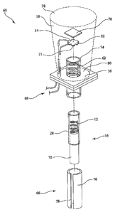
[0045] FIG. 5 shows still another exemplary embodiment 60 of an LED lighting
system. As shown, similar to system described in conjunction with FIG. 1 and
FIG. 2, the
exemplary LED lighting system has a first helical fiber 12, an LED 14, a means
16 of adjusting
the compression of the first helical fiber 12, and a light-collecting and
mixing element 18.
CA 02614439 2008-01-07
WO 2007/008724 PCT/US2006/026621
However, the exemplary embodiment of FIG. 5 also has a second helical fiber
62, and a means
66 of adjusting the compression of the second helical fiber 62.
[0046] The first helical fiber 12 and the second helical fiber 62 are both
liglit-
transmitting fibers formed in the shape of a cylindrical coil, spiral or
helix. However, the second
helical fiber 62 has a diameter that is larger tharn the diameter of the first
helical fiber 12. The
second helical fiber 62 is positioned around and is aligned coaxially with the
first helical fiber
12. The first helical fiber 12 is doped with a first wavelength converting
material, and the second
helical fiber 62 is doped with a second wavelength converting material.
[0047] The LED 14 is also a side-emitting LED having a light-emitting portion
21 and a
base portion 22. The LED 14 is positioined such that its light-emitting
portion 21 is within the
cylindrical interior space defined by the first helical fiber 12. Since the
second helical fiber 62 is
positioned around the first helical fiber 12, the LED 14 is, therefore, also
positioned within the
cylindrical interior space defined by the second helical fiber 62. Also shown
are electrical leads
68 for supplying power to the LED 14, and a backing plate 70 that acts as a
heat sink for
dissipating heat from the LED 14.
[0048] The means 16 of adjusting the compression of the first helical fiber 12
includes a
first light-transmitting tube 28 and a cylindrical plunger 72. The inner
diameter of the first light-
transmitting tube 28 is larger than the diameter of the first helical fiber
12, and the outer diameter
of the first light-transmitting tube 28 is smaller than the diameter of the
second helical fiber 62.
The first liglit-transmitting tube 28 is positioned between the first helical
fiber 12 and the second
helical fiber 62. The diameter of the cylindrical plunger 72 is slightly
smaller than the inner
diameter of the first light-transmitting tube 28. The cylindrical plunger 72
is slidingly received
within the first light-transmitting tube 28 with one end of the cylindrical
plunger 72 adjacent one
11
CA 02614439 2008-01-07
WO 2007/008724 PCT/US2006/026621
end of the first helical fiber 12. The first helical fiber 12 is positioned in
the interior of the first
light-transmitting tube 28 around the LED light-emitting portion 21 and
between the LED base
portion 22 and the cylindrical plunger 72.
[0049] The means 66 of adjusting the compression of the second helical fiber
62
includes a second liglit-transmitting tube 74 and a tubular plunger 76. The
inner diameter of the
second light-transmitting tube 74 is slightly larger than the diameter of the
second helical fiber
62. The second light-transmitting tube 74 is positioned around second helical
fiber 62. The
diameter of the tubular plunger 76 is substantially the same as the diameter
of the second helical
fiber 62. The tubular plunger 76 is slidingly received between the second
light-transmitting tube
74 and the first light-transmitting tube 28 with one end of the tubular
plunger 76 adjacent one
end of the second helical fiber 62. The second helical fiber 62 is positioned
between the first
light-transmitting tube 28 and the second light-transmitting tube 74 around
the LED light
emitting portion 21 and between the LED base portion 22 and the tubular
plunger 76.
[0050] The light-collecting and mixing element 18 is cup-shaped and receives
at least
the LED light emitting portion 21, the first helical fiber 12, and the second
helical fiber 62 in its
cup-shaped cavity. The light-collecting and mixing element 18 is for
collecting and mixing light
from the LED light-emitting portion 21, the first helical fiber 12 and the
second helical fiber 62.
The light-collecting and mixing element 18 has a closed end 36 and an open end
38. The closed
end may be formed froin a reflecting plate 80 having a reflective interior
surface. The closed end
?0 36 may further have an opening sized for allowing the second light-
transmitting tube 74 to
protrude through the closed end 36 and into the interior of the light-
collecting and mixing
element 18 and for holding the second light-transmitting tube 74 in a fixed
position.
12
CA 02614439 2008-01-07
WO 2007/008724 PCT/US2006/026621
[0051] Preferably, the tubular plunger 76 also has a longitudinal slot 78, for
allowing
support structure (not shown) to extend between the second light-transmitting
tube 74 and the
first light-transmitting tube 28, in order to hold the first light-
transmitting tube 28 in a fixed
position.
[0052] In operation, the LED light-emitting portion 21 emits light of a first
wavelength
or color. A portion of the emitted light passes through the open spaces
between the turns of the
first helical fiber 12 and the second helical fiber 62. A portion of the
emitted light is received by
the first helical fiber 12 and converted to a light of a second wavelength or
color. A portion of
the emitted light is received by the second helical fiber 62 and converted to
a light of a third
wavelength or color. Further, a portion of the light of a second wavelength
may also be received
by the second helical fiber 62 and converted to a light of a third wavelength.
The light-collecting
and mixing element 18 collects and mixes the light of a first color, the light
of a second color,
and the light of a third color, and directs the mixed light out the open end
38 of the light-
collecting and mixing element 18.
[0053] Advantageously, the cylindrical plunger 72 and the tubular plunger 76
allow the
open spaces between the turns of the first helical fiber 12 and the second
helical fiber 62,
respectively, to be adjusted by compressing or decompressing the first helical
fiber 12 and the
second helical fiber 62, thereby changing the percentages of the light of the
first color, the light
of the second color, and the light of the third color that are present in the
mixed light, and the
perceived color of the mixed light.
E. Fifth Exemplary Embodiment: Illumination Device For Simulating Neon Or
Similar
Lighting In The Shape Of A Toroid
[0054] FIG. 6 is a perspective view of a fifth exemplary embodiment 90 of an
LED
lighting system with a helical fiber filament. The fifth exemplary embodiment
90 is an
13
CA 02614439 2008-01-07
WO 2007/008724 PCT/US2006/026621
illumination device for simulating neon or similar lighting in the shape of a
toroid, such as
described in co-pending and commonly assigned application number 11/421,502,
the entire
disclosure of whicli is incorporated herein by reference.
[0055] The fifth exemplary embodiment 90 has a light-transmitting member 92
formed
of a light-transmitting medium in the shape of a toroid. The light-
transmitting member 92 has a
light-emitting surface 94. In use, the light-transmitting member 92 emits
light has a substantially
uniform intensity or brightness along the light-emitting surface 94,
simulating neon or similar
lighting in the shape of a toroid.
[0056] FIG. 7A is a side sectional-view of the fifth exemplary embodiment 90
of FIG.
6. As shown, the exemplary embodiment 90 has the toroidal light-transmitting
member 92, a
helical fiber 12, an LED 14, a means 16 of adjusting the compression of the
helical fiber 12, and
a light-directing housing 96.
[0057] The light-transmitting member 92 is a "leaky" waveguide, having both
optical
waveguide and light scattering characteristics. As a result, the light-
transmitting member 92
emits light along the light-emitting surface 94 with a uniformity and
brightness that is
characteristic of neon or similar lighting.
[0058] The LED 16 is located along the central axis of the toroidal light-
transmitting
member 92.
100591 The helical fiber 12 is positioned coaxial with the light-transmitting
member 92
!0 and the LED 16.
[0060] The light-directing housing 96 in the illustrated embodiment has a top
reflector
member 98 and a bottom reflector member 100 for directing light from the LED
14 to the light-
transmitting member 92. The top reflector member 98 is disk-shaped and covers
a top portion of
14
CA 02614439 2008-01-07
WO 2007/008724 PCT/US2006/026621
the opening defined by the toroidal light-transmitting member 92. The bottom
reflector member
100 is ring-shaped and covers the bottom portion of the opening defined by the
toroidal light-
transmitting member 92. The LED 14 is received in the opening defined by the
ring-shaped
bottom reflector member 100. Thus, the light-directing housing 96 guides light
from the LED 14
into the light-transmitting member 92, such that light is emitted only through
the light-
transmitting member 92.
[0061] As shown in FIG. 7B, the top reflector member 98 is flexible, allowing
it to also
serve as the means 16 of adjusting the compression of the helical fiber 12. By
adjusting the
compressing of the helical fiber 12, the mixture of the light from the LED 14
and the light from
the helical fiber 12 reaching the light-transmitting member 92 are adjusted,
changing the
perceived color of light emitted through the light-transmitting member 92.
F. Sixth Exemplary Embodiment: Light-Transmitting Rod
[0062] FIG. 8 shows a sixth exemplary embodiment 110 of an LED lighting system
having: a helical fiber 12, a LED 14, a light-transmitting rod 112, a
reflector 114, a substantially
clear outer sheath 116, and a reflective ring / LED holder / heat sink 118.
The LED 14 is
positioned in the reflective ring / LED holder / heat sink 118 to emit light
into a proximal end
120 of the rod 112. Preferably, the LED 14 is a top emitting LED. The helical
fiber 12 is
positioned around the rod 112, surrounding at least a portion of the rod 112.
The reflector 114
caps a distal end 122 of the rod 112 (opposite the LED 14). The substantially
clear outer sheath
116 encases the rod 112 and the helical fiber 12.
[0063] FIG. 9 shows the assembled sixth exemplary embodiment.110 of the LED
lighting system. Additionally, the light source could include potting compound
(not shown)
between the LED 14 and the light-transmitting rod 112. Further, the LED
lighting system could
CA 02614439 2008-01-07
WO 2007/008724 PCT/US2006/026621
include conductive grease (not shown) between the LED 14 and the reflective
ring / LED holder
/ heat sink 118. Additionally, the proximal end 120 of the rod 112 may be
smooth or roughed up
(lanmbertian), or curved. The sheath 116 holds index matching fluid (not
shown) for optically
coupling the rod 112 to the helical fiber 12. Alternatively, if the rod 112 is
made of a scattering
material, such as DR acrylic, then the sheath 116 and index matching fluid is
not needed for
coupling the rod 112 to the helical fiber 12.
[0064] In operation, light is generally directed along the axis of the rod
112, which acts
as a waveguide. Index matching fluid breaks the interface between the helical
fiber 12 and the
rod 112, and causes the helical fiber 12 to receive a portion of the light
emitted from the rod 112.
The wavelength converting material of the helical fiber 12 causes the light
passing through the
helical fiber 12 to have a color different than that of the LED 14. The
reflector 114 also directs
light into the helical fiber 12. Further, another reflector or mirror (not
shown) could be =
positioned at the proximal end 120 of the rod 112 to direct light into the
helical fiber 12. Thus,
the helical fiber 12 acts as a "filament."
[0065] The color (or hue) of the emitted light is controlled depending on the
following
six variables: (a) the wavelength or color of the light emitted by the LED 14;
(b) the density of
the windings of the helical fiber 12; (c) the cross-sectional shape of the
helical fiber 12; (d) the
thickness of the helical fiber 12; (e) the color and density of the dyes in
the helical fiber 12; and
(f) the color and density of any dyes in the rod 112 or sheath 116. Although
many of the
?0 variables must be pre-established, the density of the windings of the
helical fiber 12 can be
readily altered.
16
CA 02614439 2008-01-07
WO 2007/008724 PCT/US2006/026621
G. Seventh Exemplary Embodiment: Light-Transmitting Tube With Solenoid
Adjustment
[0066] In a seventh exemplary embodiment 130 as shown in FIGS. l0A and lOB, a
solenoid 132 could be used to compress the helical fiber 12. The seventh
exemplary embodiment
130 has a light-transmitting tube 131 having a formed reflector 134 in the
middle to direct light
out the sides of the rod 112. It should be noted that means of compression,
other than the
solenoid 132, could be employed. Additionally, other reflector arrangements
could be employed
without departing from the teachings of the invention. For instance, the
formed reflector 134
could be moved along the length of the rod 112 to achieve a desired effect.
[0067] By altering the density of the windings of the helical fiber 12 in this
manner, the
color (or hue) of the emitted light can be altered as desired. Significantly,
the amount of
unaltered light allowed to escape is much greater in FIG. l0A than it is in
FIG. 10B. In FIG.
l OB, the hue shifts away from the unaltered color of the light emitted from
the LED 14 and
toward the hue of the light emitted by the wavelength converting material of
the helical fiber 12.
[0068] If phosphorescent dye is used, the helical fiber 12 will continue to
emit light
even after the LED 14 is turned off. This "after glow" can be projected if the
LED light source is
placed at the focal point of a reflector or collector system.
[0069] Additional advantages may be obtained by adding dye to the tube 131.
H. Eighth Exemplary Embodiment: Light-Transmitting Tube With Multiple Parallel
Wound Helical Fibers
[0070] FIGS. 11A and 11B show an eighth exemplary embodiment 140 having
multiple
helical coils 12, 62, 142, each doped with a different wavelength converting
material. The
multiple helical coils 12, 62, 142 are wound in parallel.
17
CA 02614439 2008-01-07
WO 2007/008724 PCT/US2006/026621
1. Ninth Exemplary Embodiment: Light-Transmitting Tube With Multiple Helical
Fibers
Wound in Separate Sections
[0071] FIGS. 12A and 12B show a ninth exemplary embodiment 150 having multiple
helical coils 12, 62, 142, each doped with a different wavelength converting
material. The
multiple helical coils 12, 62, 142 are wound in separate sections.
J. Tenth Exemplary Embodiment: Bulb-Shaped Rod
[0072] FIG. 13 shows a tenth exemplary embodiment 160 of a LED lighting
system.
The tenth embodiment 160 has a bulb-shaped rod 162 having a proximal end 164
and a distal
end 166, and a reflector 168 positioned at the distal end 166. An LED (not
shown) can be
positioned to emit light into the proximal end 164 of the bulb-shaped rod 162.
In one variation,
the bulb 36 is doped with a dye. A helical fiber 12 is positioned around the
bulb-shaped rod 162.
The helical fiber 12 is doped with a wavelength converting material.
K. Eleventh Exemplary Embodiment: Dome-Shaped Spiral Fiber
[0073] Selection of dye migration resistant geometry and materials will
provide LED
lighting systems having reduced or eliminated dye migration. One aspect of the
dye migration
resistant geometry is selection of an LED that has a substantially uniform
portion across its
radiation intensity pattern. For example, FIG. 14 shows a radiation pattern
170, called a batwing
pattern, produced by LED model / part no. LXHL-MB1C available from Lumileds
Lighting,
U.S. LLC. As shown, the radiation pattern 170 is fairly uniform in the central
region, from about
,0 -20 to +20 degrees. However, radiation intensity gradients that could cause
dye migration exist
outside of the central region.
[0074] FIG. 15 shows an eleventh exemplary embodiment of an LED lighting
system
having an LED 14, a dome-shaped helical fiber 182, and an end cap 184. More
specifically, in
18
CA 02614439 2008-01-07
WO 2007/008724 PCT/US2006/026621
this embodiment, the LED 14 is selected to have a substantially uniform
radiation intensity
pattern in a central region extending about 20 degrees around the radiation
axis of the LED 14,
such as the Lumiled LED described above. The end cap 184 is spaced from the
LED 14 and
positioned such that its edges intersect the unifornn radiation intensity
pattern of the LED 14,
corresponding to the flat region shown in the batwing distribution. The end
cap 184 can be either
a transparent or translucent material doped with a dye. Since the radiation
intensity pattern is
substantially uniform across the end cap 184, migration of any dye is
minimized. The end cap
184 can also be a reflective material. The dome-shaped helical fiber 182 is
centered on the
radiation axis of the LED 14 between the LED 14 and the end cap 184. The
diameter of the fiber
is selected such that there is there is less than a 10% change in relative
intensity at any point in
the helical fiber 182.
K. Twelfth Exemplary Embodiment: Helical Fiber Encased in Light-Transmitting
Rod
[0075] FIG. 16 and FIG. 17 show a twelflh exemplary embodiment of the
invention,
having an LED 14, a helical fiber 12, and a light-transmitting rod 112. The
helical fiber 12 is
encased in the light-transmitting rod 112. Light emitted by the LED 14 is
confined by the light-
transmitting rod 112 and will be symmetrically distributed perpendicular to
the axis. The light-
transmitting rod 112 can be clear or scattering. With respect to FIG. 17, the
distal end of the
light-transmitting rod is painted or taped to reflect the light.
[0076] One of ordinary skill in the art will also recognize that additional
embodiments
are possible without departing from the teachings of the present invention or
the scope of the
claims which follow. This detailed description, and particularly the specific
details of the
exemplary embodiment disclosed therein, is given primarily for clarity of
understanding, and no
unnecessary limitations are to be understood therefrom, for modifications will
become obvious
19
CA 02614439 2008-01-07
WO 2007/008724 PCT/US2006/026621
to those skilled in the art upon reading this disclosure and may be made
without departing from
the spirit or scope of the claimed invention.